Advertisement
Quick Links
This manual contains safety information that if ignored can endan-
ger life or result in serious injury. They are indicated by this icon.
Keep the instrument protected from sun and water.
Avoid water splashes.
O PER AT IN G I N STR U C TI O N S
FOR "WD PH C L - E C L 6 " I NS T R U M E N T
Read Carefully !
ENGLISH Version
1
R1-09-08
Advertisement

Summary of Contents for Emec Micromaster WDPHCL-ECL6
- Page 1 This manual contains safety information that if ignored can endan- ger life or result in serious injury. They are indicated by this icon. Keep the instrument protected from sun and water. Avoid water splashes. O PER AT IN G I N STR U C TI O N S FOR “WD PH C L - E C L 6 ”...
-
Page 2: General Safety Guidelines
“WDPHCL” instrument complies with the following European regulations: EN60335-1 : 1995, EN55014, EN50081-1/2, EN50082-1/2, EN6055-2, EN60555,3 Based on directive CEE 73/23 c 93/68 (DBT Low voltage directive) and directive 89/336/CEE (EMC Electromagnetic Compatibility) GENERAL SAFETY GUIDELINES Danger! In emergencies the instrument should be switched off immediately! Disconnect the power cable from the power supply! When installing always observe local regulations! Manufacturer is not liable for any unauthorized use or misuse of this product that may cause injury,... - Page 3 1. Introduction WDPHCL is a fully Integrated All-in-One Swimming Pool Controller. Ideal for new construction projects the WDPHCL innovates panel mount capability into a small wall-mount package. 2 Pumps for Chlorine and pH adjustment in PVDF, small-form-factor saves space, installation time, and shipping expense.
-
Page 4: Mainboard Connections
3. Mainboard Connections Unplug instrument from main power supply then perform connections to probes and / or selected outputs by following the above picture. LEFT PUMP HEAD (pH) RIGHT PUMP HEAD (Cl) (A) STAND-BY input (B) Flow input: 1 Blue (Ground) 2 Brown (+) 3 n/a 4 Black (Signal) - Page 5 3.1 Hydraulic connections, hoses Unplug instrument from main power supply then perform connections to probes and / or selected outputs by following the above picture. Hydraulic connections are: Suction Hose with level probe and foot fi lter Delivery Hose with injection valve Discharge Hose Suction Hose.
- Page 6 3.2 Hydraulic connections, level probes Assembling foot fi lter with level probe.Level probe must be assembled with foot fi lter using the provided kit. Foot valve is made to be installed into tank’s bottom without sediments priming problem. STEP 5 STEP 4 INSERT RING AS SHOWN STEP 3...
- Page 7 3.3 Hydraulic connections, pump heads Injection Valve. Injection valve must be installed on plant from water’s input. Injection valve will open at pressure greater than 0,3bar. To Delivery hose Discharge Knob Discharge hose (connector) To Suction hose...
-
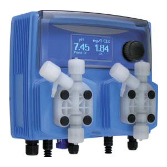
Page 8: Main Screen
4. Main Screen When into normal operating mode, WDPHCL shows the following main screen: UNITS (1) VALUES (2) PUMPS STATUS (3) LEFT RIGHT PUMP HEAD PUMP HEAD STATUS STATUS Main screen is divided int 3 zones. (1) UNITS. “pH” is the measuring unit for pH probe. “mg/l”... - Page 9 5. Quick status check From main screen rotate the wheel to review main instrument parameters and current status conditions. Current time Today date Current pH reading Current Chlorine reading Dosing alarm condition Probe failure status NO FLOW contact status Tank Level status Last pH calibration result Last pH calibration date Last Cl calibration result...
- Page 10 6. Password To grant access into “Main Menu” press the wheel from main screen and enter the passcode. If this is the fi rst time here then the passcode is 0000 (factory preset). Press wheel 5 times to enter into “Main Menu”. Otherwise press the wheel 1 time and enter the passcode.
-
Page 11: "Main Menu" List
7. “Main Menu” list To grant access into “Main Menu” enter the passcode (as described in previous chapter). Once into “Main Menu” rotate the wheel to scroll through all the options available. Set-Point (see page 12) Calibration (see page 14) Parameters (see page 20) Pumps Activities (see page 21) Instrument Reset (see page 22) - Page 12 8. “Set-Point”, pH (on/off) pH reading values can be set to operate the pH pump using 2 set-points into On/Off mode or Proportional (%). On/Off mode set the instrument to operate using two set values that enable or disable the pH pump. To use this mode move cursor on “Working Mode”.
- Page 13 8. “Set-Point”, pH (on/off) ON/OFF mode while dosing ACID Set pH value at 7.00 OFF and 7.10 ON. Instrument will leave the pH pump active until reading value will decrease up to 7.00pH At 7.00pH the pH pump will be disabled until reading value will increase up to 7.10pH. Waiting Time: to let pump operate at pulses per minutes add one or more minute (1pulse every xx minutes).
- Page 14 8.1 “Set-Point”, pH (proportional) pH reading values can be set to operate the pH pump using 2 set-points into On/Off mode or Proportional (%). Proportional mode set the instrument to operate using a calculated percentage between two set values that enable or disable the pH pump.
- Page 15 8.2 “Set-Point”, Cl (on/off) Cl reading values can be set to operate the Chlorine pump using 2 set-points into On/Off mode or Proportional (%). On/Off mode set the instrument to operate using two set values that enable or disable the Chlorine pump. To use this mode move cursor on “Working Mode”.
- Page 16 8.3 “Set-Point”, Cl (proportional) Cl reading values can be set to operate the pH pump using 2 set-points into On/Off mode or Proportional (%). Proportional mode set the instrument to operate using a calculated percentage between two set values that enable or disable the Chlorine pump.
- Page 17 9. “Probe Calibration”, pH pH calibration procedure involves two calibration points and it requires two buffer solutions. Default buffer solutions are pH 4.00 and pH 7.00. pH reading value can be also 30°C temperature compensated from “pH compensation” menu. From “Menu Calibration” choose “pH probe”. In the following example instrument will calibrate pH using default buffer solutions values.
- Page 18 9. “Probe Calibration”, pH Calib 2nd Point. Move wheel on “P2” then press wheel to enter into second point calibration submenu. Prepare 4.00pH buffer solution and dip probe’s sensor on it. Wait until reading value is stable and according to buffer solution value move wheel until it is the same on display (“Cal.
- Page 19 9.1 “Probe Calibration”, Cl Cl calibration procedure involves probe’s selection, Zero (P1) and 2nd Point (P2) calibration. From “Menu Calibration” choose “Cl probe”. Note: This procedure assumes that instrument is correctly confi gured and a working Chlorine probe connected and installed on system. Measurement must be performed using plant water. Otherwise unattended results may occurr.
- Page 20 10. “Parameters” From “Menu Calibration” choose “Parameters”. This menu allows to set a delay (max 60 minutes) before pumps begin to feed. Furthermore use this menu to set pH pump startup priority and to change default passcode. Feeding Delay. Move on “Feeding Delay” then press wheel. Choose a value between 0 (disabled) and 60 minutes (maximum delay time).
- Page 21 11. “Pumps Activities” From “Menu Calibration” choose “Pumps activities”. This menu allows to manually operate one or both the pumps for a settable time. Move on “Mode” then press wheel. Choose “Man. Pump1” for manually operate pH pumps or “Man. Pump2” for Cl pump.
- Page 22 11. “Instrument Reset” To restore instrument to its default values (including password) once into “Instrument Reset” menu, press wheel then change value to “ON”, press wheel again, move on “OK” then fi nally press wheel. The instrument display will show “CHECKSUM ERROR”.
- Page 23 13. “Dosing Alarm” Use this menu to assign a maximum time to the pumps for reaching the setpoint. If set time ends and the pumps are still dosing, within this menu is possible to STOP them or just to show an alarm message. Function can be disabled selecting “OFF”...
- Page 24 14. “International” Use this menu to set international parameters as UNIT FORMAT (Europe IS or USA), Local Time and Date. Format. Use this option to use European or USA units format. See table for differencies. EUROPE IS (Internationl Standard) Date (DD/MMM/YY) Date (MMM/DD/YY) Time 24h Time AM / PM...
- Page 25 15. “Probe Failure” Use this menu to assign a maximum time to connected probes to stay stuck. A stuck probe (it remains on same value for some time) means that probably probe itself is damaged. Within this menu is possible to STOP pumps or just to show an alarm message (probe failure) .
- Page 26 16. “pH Compensation” To enable 30°C temperature compensation for pH probe press wheel then choose “ON”. For disabling temperature compensation choose “OFF”. To end procedure move cursor on “OK” and press wheel to proceed to “Save” request screen. Move wheel on “YES” to save or “NO”...
- Page 27 18. “Flow Contact” Flow contact (locate connection on page 4) can be enabled to stop all dosing activities using a N.O. contact (normally opened contact) or N.C. contact (normally closed contact). Move wheel for enabling and changing contact logic (N.O. or N.C).
-
Page 28: Technical Information
20. Technical information. Power supply: 230 VAC (190÷265 VAC) pH range: 0 ÷14 ; Cl range: 0÷10 mg/l Pump Strokes: 0 ÷ 180 Suction Height: 1,5 metres Environment Temperature: -10 ÷ 45°C (14 ÷ 113°F) Chemical Temperature: 0 ÷ 50°C (32 ÷ 122°F) Installation Class: II Pollution Level: 2 Audible Noise (single head): 74dbA... - Page 29 21. Dimensions. mm [inches] Information on this manual may contain technical inaccuracies or typographical errors. The information contained may be changed at any time without prior notifi cation or obligation.
- Page 30 22. Index CE Conformity Declaration page 2 General Safety Guidelines page 2 Introduction page 3 The wheel page 3 Mainboard connections page 4 Hydraulic connections, hoses page 5 Hydraulic connections, level probes page 6 Hydraulic connections, pump heads page 7 Main screen page 8 Quick status check...
- Page 32 When dismantling this instrument please separate material types and send them according to local recycling disposal requirements. We appreciate your efforts in supporting your local Recycle Environmental Program. Working together we’ll form an active union to assure the world’s invaluable resources are conserved.
Need help?
Do you have a question about the Micromaster WDPHCL-ECL6 and is the answer not in the manual?
Questions and answers