Table of Contents
Advertisement
Securlift sagl
Viale Serfontana 12
CH - 6834 Morbio Inferiore
Switzerland
INDEX
INTRODUCTION ................................................................................................................................................... 2
SYSTEM DESCRIPTION ......................................................................................................................................... 2
TECHNICAL SPECIFICATIONS ................................................................................................................................ 3
TOPOGRAPHIC DRAWINGS ................................................................................................................................. 5
CABINETS .......................................................................................................................................................... 13
INTERNAL LAYOUT ............................................................................................................................................ 19
PRELIMINARY TEST............................................................................................................................................ 20
INSULATION TEST .............................................................................................................................................. 21
DZSM - DOOR ZONE SAFETY MODULE TEST....................................................................................................... 22
RUN TIME SUPERVISION TEST ........................................................................................................................... 23
OVERSPEED GOVERNOR REMOTE TEST. ............................................................................................................ 23
FINAL LIMIT SWITCHES TEST.............................................................................................................................. 24
EN 81-20 - A3 AMENDEMENT (EN 81-1 & EN 81-2) ........................................................................................... 25
ELGO LIMAX - ABSOLUTE POSITIONING SYSTEM .............................................................................................. 29
SEC-3Q - CONTROLLER MOTHER BOARD .......................................................................................................... 31
SEC-3AUX - BOARD WITH AUXILIARY RELAY ..................................................................................................... 35
SEC-3KBD - USER INTERFACE KEYPAD ............................................................................................................... 37
SEC-3S - SAFETY CIRCUIT BOARD REV. 2.0 ........................................................................................................ 40
SEC-3C - CAR BOARD ........................................................................................................................................ 43
SEC-3TRG - COP BOARD .................................................................................................................................... 46
SEC-3I/O - EXTENSION BOARD .......................................................................................................................... 48
SEC-2L - FLOOR NODE BOARD........................................................................................................................... 50
SEC-2LPI - LANDING DISPLAY BOARD ................................................................................................................ 54
SEC-2FDR - ALARM BATTERY CHARGER ............................................................................................................ 55
MANUAL RESCUE OPERATION INSTRUCTION .................................................................................................... 57
HELPY L300 - TELEPHONE DIALLER .................................................................................................................... 59
LEGENDA ........................................................................................................................................................... 60
SOFTWARE DOWNLOADING ............................................................................................................................. 66
SOFTWARE UPDATING BY USB MEMORY STICK ................................................................................................ 69
V3F SPEED SELECTION ....................................................................................................................................... 70
X:\Ufficio Tecnico\DOCUMENTAZIONE\SECUR 3\Manuali\IM_SEC3_02.01_en.docx - 09/10/2017
Tel. +41 (0)91 682 7681
Fax +41 (0)91 682 6154
info@securlift.com
www.securlift.com
Advertisement
Table of Contents

Summary of Contents for Securlift Secur3
-
Page 1: Table Of Contents
Securlift sagl Tel. +41 (0)91 682 7681 Viale Serfontana 12 Fax +41 (0)91 682 6154 CH - 6834 Morbio Inferiore info@securlift.com Switzerland www.securlift.com INDEX INTRODUCTION ..............................2 SYSTEM DESCRIPTION ............................2 TECHNICAL SPECIFICATIONS ..........................3 TOPOGRAPHIC DRAWINGS ..........................5 CABINETS ................................13 INTERNAL LAYOUT ............................ -
Page 2: Introduction
follows: IM_SEC3_02.01_en.docx Introduction The SECUR 3 modular system allowed our designers to develop innovative and reliable microprocessor based controllers. This system assigns to peripheral co-processors the activation of related inputs and outputs. In this application every node of the system is connected by a simple two-wire connection. The serial communication system which is used between boards in car and in control panel is based on CAN (CONTROLLER AREA NETWORK). -
Page 3: Technical Specifications
follows: IM_SEC3_02.01_en.docx Technical specifications BASIC SPECIFICATION • Modular system up to 32 floors (64 services). • microprocessor • CAN (Controller Area Network) serial transmission from controller to: • Car, landings, inverter Interfaces • Removable user interface for parameter setting and controller diagnostic: •... - Page 4 follows: IM_SEC3_02.01_en.docx Signalisation • 24 VDC – 1W per output • Gong / voice announcer in 4 languages (standard) – other languages upon request • car position indication: 1 wire per floor, 7 segment, dot matrix, LCD binary • Other signalisation: •...
-
Page 5: Topographic Drawings
follows: IM_SEC3_02.01_en.docx Topographic drawings 5/70... - Page 6 follows: IM_SEC3_02.01_en.docx 6/70...
- Page 7 follows: IM_SEC3_02.01_en.docx 7/70...
- Page 8 follows: IM_SEC3_02.01_en.docx 8/70...
- Page 9 follows: IM_SEC3_02.01_en.docx 9/70...
- Page 10 follows: IM_SEC3_02.01_en.docx 10/70...
- Page 11 follows: IM_SEC3_02.01_en.docx 11/70...
- Page 12 follows: IM_SEC3_02.01_en.docx 12/70...
-
Page 13: Cabinets
follows: IM_SEC3_02.01_en.docx Cabinets 13/70... - Page 14 follows: IM_SEC3_02.01_en.docx 14/70...
- Page 15 follows: IM_SEC3_02.01_en.docx 15/70...
- Page 16 follows: IM_SEC3_02.01_en.docx 16/70...
- Page 17 follows: IM_SEC3_02.01_en.docx 17/70...
- Page 18 follows: IM_SEC3_02.01_en.docx 18/70...
-
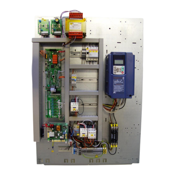
Page 19: Internal Layout
follows: IM_SEC3_02.01_en.docx Internal layout Control panelovra Car roof connection box 19/70... -
Page 20: Preliminary Test
follows: IM_SEC3_02.01_en.docx Preliminary test In order to perform preliminary test a TEMPORARY command box has to be connected to controller, strictly following the below diagram. ! DO NOT USE THE PRE-WIRED INSPECTION BOX DELIVERED WITH THE CONTROLLER ! Do not install the car roof box (board SEC-3C) Referring to installation electric drawings, connect following circuits: a) Mains supply - terminals M1,M2,M3 (ref. -
Page 21: Insulation Test
follows: IM_SEC3_02.01_en.docx Insulation test Preliminary operation • Insulation test have to be performed after complete and correct functional test of the lift have been made. • Position the car between two floors and check that all doors are closed. • Check that AM circuit breaker (on control panel) is closed. •... -
Page 22: Dzsm - Door Zone Safety Module Test
follows: IM_SEC3_02.01_en.docx DZSM - Door Zone Safety Module test When ADO (advance door open) and/or ACL (re-levelling) are provided, a Safety Module is fitted inside the controller. The safety module allows the car movement inside door zone with door opened. In order to test the device proceed as follows: Verify controller software reviosion = 02.52D or further Verify parameter 02.16 = Yes [DZSM Control]... -
Page 23: Run Time Supervision Test
follows: IM_SEC3_02.01_en.docx Run Time Supervision test Hydraulic lift • manually block the car movement (e.g. disconnect vanes, close oil tap, disconnect power unit) • register a call • car doesn’t move, and after the set time in 01.07 display shows Run Time Superv. •... -
Page 24: Final Limit Switches Test
follows: IM_SEC3_02.01_en.docx Final Limit Switches test Traditional shaft (magnets and/or motor encoder) Upper final limit switch FLS:U • register a call for top floor. • after deceleration (car at low speed) disconnect SC3 connector on SEC-3S board • car will continue its run until upper final limit switch In order to set the lift back in service restore connections, then lower the car below limit switch, then press and hold Clear for 10 sec. -
Page 25: En 81-20 - A3 Amendement (En 81-1 & En 81-2)
follows: IM_SEC3_02.01_en.docx EN 81-20 – A3 amendement (EN 81-1 & EN 81-2) Functionality test of the brake monitoring • For traction elevators with double brake microswitch This procedure is intended to be applied on systems with FUJI drives only. CONDITIONS TO START THE TEST: ELEVATOR INSTALLED AND WORKING CORRECTLY TEST INSTRUCTION: 1. - Page 26 RESET button on the SEC-3Q main board NOTE: The test system provided by SECURLIFT maintains the same safety level of the normal operating condition. The speed of the system reached at the moment you open the security contact depends on the speed reached by the car, and therefore by the acceleration that occurs in the 20cm of floor zone.
- Page 27 follows: IM_SEC3_02.01_en.docx Electrical connection of the A3 test Kit 27/70...
- Page 28 follows: IM_SEC3_02.01_en.docx Safety circuit after insertion of the A3 test kit 28/70...
-
Page 29: Elgo Limax - Absolute Positioning System
follows: IM_SEC3_02.01_en.docx ELGO LIMAX – absolute positioning system Following procedures have to be performed only after lift installation is completed, with all safeties installed and checked. Connect programming keypad to SEC-3Q board by the RJ45 cable Check parameter 01.02 – Number of stops [ Check parameter 02.01 –... - Page 30 follows: IM_SEC3_02.01_en.docx 7.2. Set parameter 07.04 – Floors Setup = [SETTING]; press M then to confirm; display shows P01 [00000] 7.3. Move the car to bottom floor level. Down run will be in inspection mode only, at low speed. 7.4. With car at bottom floor level press M; the level is registered and the system is now ready for second floor level acquisition;...
-
Page 31: Sec-3Q - Controller Mother Board
follows: IM_SEC3_02.01_en.docx SEC-3Q – controller mother board SEC-3Q is the main board of the system, located inside the control panel. 31/70... - Page 32 follows: IM_SEC3_02.01_en.docx Dip switch SW1 PRG = always OFF WD = Watch Dog enable – always ON CAN2 = CAN termination. Refer to installation drawing – page 90. Dip switch SW2 DOOR = doors disable CALL = landing calls disable S1 = future use S2 = automatic calls test LED’s...
- Page 33 follows: IM_SEC3_02.01_en.docx Connectors On-board connectors are located in order to group all signals depending on their address (car, shaft, machine room). Connectors name and pin numbering are printed on the board as follows: • AUX • USB Connection to board with auxiliary USB plug •...
- Page 34 follows: IM_SEC3_02.01_en.docx CAN1 (serial connection to car) CAN2 (serial connection to landings and multiplex) 1 CH CAN high 1 CH CAN high 2 CL CAN low 2 CL CAN low 3 +24 VDC 3 +24 VDC 4 GND 4 GND 5 +24 VDC 5 +24 VDC...
-
Page 35: Sec-3Aux - Board With Auxiliary Relay
follows: IM_SEC3_02.01_en.docx SEC-3AUX – board with auxiliary relay SEC-3AUX board increases mother board functionalities. It is optionally used for door control, hydraulic valves drive, inverter interface. 35/70... - Page 36 follows: IM_SEC3_02.01_en.docx Connectors AUX = connection to SEC-3Q board P11 (supervision inputs) P12 (outputs) Out of service 1 OSI 1 OIL P Oil pressure 2 OP A A side door OPEN command 2 OIL T Oil temperature ...
-
Page 37: Sec-3Kbd - User Interface Keypad
follows: IM_SEC3_02.01_en.docx SEC-3KBD – user interface keypad SEC-3KBD is the user interface. It allows monitoring an programming of the system. At power-on the display shows software revision index, software revision date and motor drive code. Please refer to PM (programming manual) for detailed parameter list. 37/70... - Page 38 follows: IM_SEC3_02.01_en.docx Connectors On-board connector (PBC) allows connection to SEC-3Q board by a standard RJ45 serial cable. Trimmers Trimmer PT1 adjusts the LCD contrast. Buttons When in normal mode: • : OPEN door command • : CLOSE door command • : increase destination floor •...
- Page 39 follows: IM_SEC3_02.01_en.docx User interface display – main screen Sensors: present floor : destination floor Misc information • S___: floor sensor succession: • _D__: floor sensor • Elevator state (see “state Misc information in succession: • __Z_: floor sensor messages” at the end of the •...
-
Page 40: Sec-3S - Safety Circuit Board Rev. 2.0
follows: IM_SEC3_02.01_en.docx SEC-3S – safety circuit board Rev. 2.0 SEC-3S board is the interface to all devices related to safety circuit. 40/70... - Page 41 follows: IM_SEC3_02.01_en.docx LED’s In the following tables all LED symbols are shown with power ON, with car parked at bottom floor, after reset drive has been accomplished. = lit = off = blinking safety circuit START: AM ...
- Page 42 follows: IM_SEC3_02.01_en.docx SC3 (monostable shaft switches) Not used UP magnetic switch/ DOOR ZONE magnetic 2 IU/IZ1 switch (ELGO Limax) DOWN magnetic switch 3 ID DOOR ZONE magnetic switch 4 IZ/IZ2 5 GND SM1 (machine room safeties) SQ4 (ADO-ACL safety module interface) BRK: manual brake switch...
-
Page 43: Sec-3C - Car Board
follows: IM_SEC3_02.01_en.docx SEC-3C – car board SEC-3C is the interface between controller and all car devices. Dip switches WD = Watch Dog enable - always ON PRG = always OFF Jumper J3 = not used 43/70... - Page 44 follows: IM_SEC3_02.01_en.docx In the following tables all LED symbols are shown with power ON, with car parked at bottom floor, after reset drive has been accomplished. = lit = off = blinking +24V 24 VDC (fuse F1) ...
- Page 45 follows: IM_SEC3_02.01_en.docx C12 (various I/O) CAN1IN (serial link to controller – SEC-3Q) 1 IN1 input door motor temperature 1 CH – CAN high 2 IN2 input car doors closed while Bypass 2 CL – CAN low 3 +24 VDC 3 IN3 future use 4 GND 4 IN4...
-
Page 46: Sec-3Trg - Cop Board
follows: IM_SEC3_02.01_en.docx SEC-3TRG – COP board SEC3-TRG is the Car Operation Panel board. It collect sall the calls and drives all the signalizations. 46/70... - Page 47 follows: IM_SEC3_02.01_en.docx Connectors CT10 1 O_EME In Emergency output 1 UPD: UP direction arrow Overload 2 DND: DOWN direction arrow 2 O_GNG aux. Gong output 3 +24 VDC 3 FRD2 2 Fireman’s key 4 GND 4 IN calls disable input 5 +24 VDC 6 GND CT11 (uscite posizione cabina)
-
Page 48: Sec-3I/O - Extension Board
follows: IM_SEC3_02.01_en.docx SEC-3I/O – extension board SEC-3I/O board is the interface for car calls (over 16 services) or for some special function. Each board collects up to 8 calls. Appropriate setting of dip-switches configures the board function. LED’s In the following tables all LED symbols are shown with power ON, with car parked at bottom floor, after reset drive has been accomplished. - Page 49 follows: IM_SEC3_02.01_en.docx PX (smoke detector - dip 3 ON) PX (smoke detector - dip 3+1 ON) 1 floor 1 1 floor 9 2 floor 2 2 floor 10 3 floor 3 3 floor 11 4 ...
-
Page 50: Sec-2L - Floor Node Board
follows: IM_SEC3_02.01_en.docx SEC-2L – floor node board SEC-3L is the landing interface board. It collects landing calls, buttons and key switches, and drives all landing signalisations. 50/70... - Page 51 follows: IM_SEC3_02.01_en.docx Dip switch ID floor - bin 1 ID floor - bin 2 ID floor - bin 4 ID floor - bin 8 ID floor - bin 16 ID floor - bin 32 side B selection (if selective openings doors) WD = Watch Dog enable –...
- Page 52 follows: IM_SEC3_02.01_en.docx ID lift - bin 1 ID lift - bin 2 ID lift - bin 3 PRG = always OFF Jumper CAN = REFER to installation drawings – page 90. LED’s In the following tables all LED symbols are shown with power ON, with car parked at bottom floor, after reset drive has been accomplished.
- Page 53 follows: IM_SEC3_02.01_en.docx CAN UP (supply and serial link) CAN DN (supply and serial link) 1 CAN H 1 CAN H 2 CAN L 2 CAN L 3 +24 VDC 3 +24 VDC 4 GND 4 GND 5 +24 VDC 5 +24 VDC 6 GND 6 GND UPB (up button)
-
Page 54: Sec-2Lpi - Landing Display Board
follows: IM_SEC3_02.01_en.docx SEC-2LPI – Landing display board SEC-2LPI is the car position indicator driver at landings, when serial landing connection is used. It fits on the SEC-2L board by connector CPI. DSP (car position output) segment a bin 1 dec 1 floor segment b bin 2... -
Page 55: Sec-2Fdr - Alarm Battery Charger
follows: IM_SEC3_02.01_en.docx SEC-2FDR – alarm battery charger SEC-2FDR is the alarm interface board, and provides for battery charge and check. Jumper J1 = selects the battery size to be charged: • open = 2.2 Ah • closed = 7 Ah J2 = selects the car emergency light output contact (CAL/4): •... - Page 56 follows: IM_SEC3_02.01_en.docx Connectors DZI (car at floor indicazion) ALC (alarm output) 1 + positive LED out 1 ALC alarm output N.O. negative LED out 2 ALC ALB (machinery alarm button) ISE (machinery intercom) 1 PH A alarm button N.O.
-
Page 57: Manual Rescue Operation Instruction
follows: IM_SEC3_02.01_en.docx Manual rescue operation instruction AVAILABLE on BRUSHLESS GEARLESS only Nominal speed reference setting – to be performed at lift commissioning 1. Set rated speed in parameter 50.01 2. Reset parameter 50.02 by pressing and holding 3 sec. both and buttons 3. - Page 58 follows: IM_SEC3_02.01_en.docx 4. With FUJI inverter a. Verify speed and direction by checking led’s on SEC-3Q board (fig.3) = UP direction = speed ALARM = speed pre-alarm OK = speed OK ...
-
Page 59: Helpy L300 - Telephone Dialler
follows: IM_SEC3_02.01_en.docx HELPY L300 – Telephone dialler Quick programming • Set telephone switch to “T” (tone) Enter programming mode Automatic answer * 0 # 64 5 answer after 5 rings 79 01 # language selection = English 65 9 max. speech time 79 07 # language selection = Dutch 66 0 telephone network... -
Page 60: Legenda
follows: IM_SEC3_02.01_en.docx Legenda Electrical drawings use the following abbreviations: DEVICES abbreviation description notes 12:H HIGH speed valve 12:N DOWN valve ALARM bell ALM-GER Gervall UCM supply unit ALARM signal at landings (legge 13) SAFETY circuit braker Interruttore magneto/termico PAWL DEVICE Minicontattore PAWL DEVICE BALAUSTRADE contact Manual BRAKE lever contact... - Page 61 follows: IM_SEC3_02.01_en.docx INSPECTION limit switch EN 81-21 FCM:D DOWN INSPECTION limit switch EN 81-21 FCM:U UP INSPECTION limit switch EN 81-21 ADDITIONAL INSPECTION limit switch EN 81-21 FCU:U Fine corsa ulteriore discesa EN 81-21 FIRE RECALL switch FLS:D DOWN final limit switch FLS:U UP final limit switch FIA module contact...
- Page 62 follows: IM_SEC3_02.01_en.docx STAR contactor DELTA contactor Emergency voltage contactor Normal voltage contactor UP contactor Blain A3 valve PUNTONE in fossa Car LOCKING contact LOC… Car call disable contact/key/switch Contatto parapetto mobile EN 81-21 Segnalazione OK in fossa Power terminal MAN:T INSPECTION contactor (EN 81-21) Dispositivi controllo SERRATURE porte piano Bobina modulo FIA...
- Page 63 follows: IM_SEC3_02.01_en.docx Shaft light relay RMAN INSPECTION relay Relè FUORI SERVIZIO Fireman’s drive relay RR:A A door BRAKING RESISTOR RR:B B door BRAKING RESISTOR RRCH EU delay Timer RSENS DYNATECH A3 sensor relay RSIC Dynatech A3 safety circuit relay Overspeed governor rope tension contact UP bistable synchronisation sensor INSPECTION enable button FAN/LIGHT relay...
- Page 64 follows: IM_SEC3_02.01_en.docx Thermal relay THR:H Thermal relay for high speed winding THR:L Thermal relay for low speed winding TINSP Inspection contactor TKAK Minicontattore controllo modulo FIA TKAK FIA module contact SOFT STOP contactor Door transformer 3phase retiring ramp contactor Re-levelling contactor Trasformatore alimentazione PAWL DEVICE Trasformatore alimentazione centralina Moris DOMINO Transformer...
- Page 65 follows: IM_SEC3_02.01_en.docx RLV/2 Car roof lighting Inspection box safeties Safety gear switch / Final limit switch in car Monostable Magnetic Switches: • Shaft count (IU - ID) • Car at floor (IM) • Door Zone (IZ; IZ1; IZ2) Speech unit loudspeaker Shaft Connectors abbreviation description...
-
Page 66: Software Downloading
IM_SEC3_02.01_en.docx Software downloading It is possible get the needed program following the link: http://mcu.emea.fujitsu.com/mcu_tool/software.htm FLASH PROGRAMMER 16FX software for Controller board (SECURLIFT internal use only). http://www.spansion.com/Pages/mcu_download.aspx?redirect=/EnglishDownloads/EDG/binary/zip/product/mic om/tools/downloads/flash/PCW16FX-V01L15.zip FLASH PROGRAMMER 16LX software for all other boards. http://www.spansion.com/Pages/mcu_download.aspx?redirect=/EnglishDownloads/EDG/binary/zip/product/mic om/tools/downloads/flash/pcw16lx-v01l27.zip Drivers for the programming cable SEC-2PRG can be downloaded at: http://www.ftdichip.com/Drivers/CDM/CDM%20v2.12.12%20WHQL%20Certified.exe... - Page 67 follows: IM_SEC3_02.01_en.docx SEC-2L board = MB90F497/G SEC-3Q board = MB96F338R/U/Y SEC-3C board = MB90F345A/CA/AS/CAS SEC-3TRG board= MB90F345A/CA/AS/CAS SEC-3IO board= MB90F362E/ES/TES 6. Select “Crystal frequency” at 4MHz. Select “Crystal Frequency” a 4MHz. 7. Select COM port according to interface cable installation. Select COM port Set COM1 port Set COM1 port...
- Page 68 follows: IM_SEC3_02.01_en.docx 8. Open file to be downloaded 9. Start downloading Start downloading RX and TX led’s blink. 68/70...
-
Page 69: Software Updating By Usb Memory Stick
follows: IM_SEC3_02.01_en.docx 10. While pressing the RESET button set the board dip switches SW1 as follows: WD = ON • RS = ON (if present) • PRG = OFF • 11. Set all default parameters (param. 98.02 = Yes) 12. Exit and save (param. 00.01 – Save changes - ok) 13. -
Page 70: V3F Speed Selection
follows: IM_SEC3_02.01_en.docx V3F speed selection HIGH INSP VACON VACON FUJI P3/1 P3/2 P3/3 High P2.2.7 P2.2.5 50Hz - 1500rpm Intermediate High P2.2.11 P2.2.9 40/50Hz - 1200/1500rpm Intermediate Low P2.2.12 P2.2.10 30Hz - 900rpm Short floors ...
Need help?
Do you have a question about the Secur3 and is the answer not in the manual?
Questions and answers