
Subscribe to Our Youtube Channel
Summary of Contents for Osstem K3
- Page 1 UNIT CHAIR Dental Unit and Chair User Manual OS-UM-C002 ver.2 IMPORTANT NOTES 2460 Please read this manual thoroughly before using the equipment to ensure safe and correct usage.
- Page 2 Check the matters below Before you read this user manual before reading this user manual Used in cautionary matters for safety Symbol Name Function You may damage the equipment if you do not observe the following Caution instructions. You may lose your life or sustain serious injury if you do not observe the Warning following instructions.
- Page 3 Provides convenience in using instruments (Hand-piece, Scaler, Suction, etc) during treatment. This User Manual This user manual is for the K3 Mount/K3 Cart model of Osstem Implant Co., Ltd. (hereinafter referred to as Osstem) and issued on 2017. 08. 10 ...
- Page 4 Matters requiring attention for safety Related to installation This Product should be installed by Osstem or an expert designated by Osstem, based on the installation manual. You should not do the following. • Do NOT use this product in conditions other than the indicated power supply voltage [V~], frequency [㎐] and acceptable current [A] (or power consumption) specifications.
- Page 5 Matters requiring attention for safety Matters requiring attention regarding power supply You may lose your life or sustain serious injury if you do not observe the following instructions. • Wipe off foreign substances (dust, water) on the power plug terminal and contact part with dry cloth regularly.
- Page 6 * Guidance and manufacturer’s declaration - Electromagnetic emission • The K3is intended for use in the electromagnet environment specified below. • The customer or the user of the K3 should assure that it is used in such an environment. Emission...
- Page 7 70 % U 70 % U interruptions, it is recommended input lines for 25, 30 cycles for 25, 30 cycles that the K3 be powered from an IEC 61000-4-11 <5 % U for 5 s <5 % U for 5 s...
- Page 8 If the measured field strength in t he location in which the K3 is used exceeds the applicable RF compliance level above, the K3 shoul d be observed to verify normal operation. If abnormal performance is observed, additional measure s may be necessary, such as re- orienting or relocating the K3.
- Page 9 * Recommended separation distance between portable and mobile RF communication equipment and the K3 • The K3is intended for use in an electromagnetic environment in which radiated RF disturbances are controlled. The customer or the user of the K3can help prevent electromagnetic interference by...
- Page 10 Matters requiring attention for safety Matters requiring attention regarding the operation of the equipment You should not do the following. • Do NOT put an object or your finger or foot in the part or range of operation of the body such as under the Seat or Backrest joint.
- Page 11 • The user must wear personal protective equipment to prevent the infection during dental procedures.(e.g. gowns, lab coats, gloves, masks, and protective eyewear or face shields) • Recommended that the K3 use in the combination with anti suction equipment and amalgam separator device.
- Page 12 Matters requiring attention for safety On matters requiring attention regarding the operation of the equipment You may damage the equipment if you do not observe the following instructions. • The patient and operator may be injured or harmed by the operation of the examining table. - Both patient and operator should take caution while the examining table is operating.
-
Page 13: Table Of Contents
Contents 1. Product Description…………………………………………………………………...……... 1-1. Appearance………………………………………………………….………………………………..……………………. 1-2. Description of the exterior………………………………………….………………………………………..……. 2. Putting the system into operation………………………………..…………….……..2-1. Socket Outlet……………………………………………………………………………………………..…….………... 2-2. Main Switch………………………………………………………………………………………………..……………… 3. Patient Chair………………………………………………………………………….………..3-1. Adjusting the Patient Position….……………………………………………………………….……………..3-2. Adjusting the Armrest……………………………………………………………………………….……………..3-3. Adjusting the Headrest..……………………………………………………………………………………………. 3-4. - Page 14 11. Dental Light - Option……………………………………………………………...…….….. 11-1. Dental Light……………………………………………………….………………………………..………..…………… 12. Other Accessories - Option…………………………………………..………..……..12-1. Monitor Arm..…………………………………………………………………………………………..……………..12-2. HANARO Console..…………………………………………………………………………………..……..………… 13. Cleaning and Maintenance…………………………………………………………..….. 13-1. Barrier Protection..…………………………………………………………………………………………………..… 13-2. Upholstery…………………………………………………………………………………………………………..…..13-3. Cleaning the Unit………………………………………………………………………………………………..…..13-4. Cleaning the 3-Way Syringe………………………………………………………………………………..…… 13-5. Saliva Ejector...…………………………………………………………………………………………………..………. 13-6.
-
Page 15: Product Description
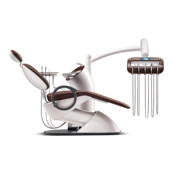
1. Product Description 1-1. Appearance 1-1-1. Mount Type UNIT CHAIR [OS-UM-C002 Ver.2]... - Page 16 1-1-2. Cart Type UNIT CHAIR [OS-UM-C002 Ver.2]...
-
Page 17: Description Of The Exterior
1-2. Description of the exterior 1-2-1. Mount Type ⑥ ⑦ ① ⑪ ⑤ ⑫ ② ⑩ ④ ⑨ ③ ⑧ ⑬ Front Side ▶ Applied Part : Head Rest/Back Rest/Seat/Arm Rest/3-Way Syringe/Saliva Ejector(large, small) UNIT CHAIR [OS-UM-C002 Ver.2]... - Page 18 ① Foot Control: Device with which the doctor moves the Patient Chair up and down, and controls devices such as the Hand-piece, using the foot. ② Doctor’s Table: Table installed with various devices necessary for treatment; consists of various switches for operating instruments and the Treatment Chair. ③...
- Page 19 1-2-2. Cart Type ⑥ ⑦ ① ⑪ ⑤ ⑫ ② ⑩ ⑨ ⑬ ③ ④ ⑧ Front Side ▶ Applied Part : Head Rest/Back Rest/Seat/Arm Rest/3-Way Syringe/Saliva Ejector(large, small) UNIT CHAIR [OS-UM-C002 Ver.2]...
- Page 20 ① Foot Control: Device with which the doctor moves the Patient Chair up and down, and controls devices such as the Hand-piece, using the foot. ② Doctor’s Table: Table installed with various devices necessary for treatment; consists of various switches for operating instruments and the Treatment Chair. ③...
-
Page 21: Putting The System Into Operation
2. Putting the System into Operation 2-1. Socket Outlet 2-1-1. Basic Type Before Use! • Be sure to check the power source used in the equipment. (100-120/220-240V~) • Connect the equipment’s power cord to the electrical outlet. ① [Fig. 1] Positions of the Chair Main Plug Socket Name Function and operation method Reduce the transfer of electromagnetic noise between the drive... - Page 22 2-1-2. Option Type Before Use! • Be sure to check the power source used in the equipment. (100-120/220-240V~) • Connect the equipment’s power cord to the electrical outlet. ② ① [Fig. 2] Socket Outlet Name Function and operation method Reduce the transfer of electromagnetic noise between the drive ①...
-
Page 23: Main Switch
2-2. Main Switch Before Use! • Be sure to check the power source used in the equipment. (100-120/220-240V~) • Connect the equipment’s power cord to the electrical outlet. • Do not touch the power plug with wet hands. ■ How to switch on Turn the main switch ON The Main Switch turns green if you turn on power and the Doctor’s Table Panel... -
Page 24: Patient Chair
3. Patient Chair 3-1. Adjust the Patient Position 3-1-1. Adjustment by the Doctor Patient Chair Positioning Button [Fig. 4] Composition of the Doctor’s Table Panel Button Function LCD Screen Description Seat moves Seat moves upward while the button is pressed. upward Seat moves Seat moves downward while the button is... - Page 25 3-1-2. Adjustment by the Assistant Patient Chair Positioning Button [Fig. 5] Composition of the Assistant Table Panel Button Function LCD Screen Description Seat moves Seat moves upward while the button is pressed. upward Seat moves Seat moves downward while the button is downward pressed.
- Page 26 3-1-3. Adjustment using the Foot Controller Buttons for adjusting treatment position [Fig. 6] Foot Controller Direction Function LCD Screen Description Seat moves Seat moves upward while the joystick is pushed upward in the indicated direction. Seat moves Seat moves downward while the joystick is downward pushed in the indicated direction.
-
Page 27: Adjusting The Armrest
3-2. Adjusting the Armrest Before Use! • Only the Armrest on the right-hand side is capable of the function described below. • The Armrest can be rotated 60º downward to minimise discomfort of the patient in getting on and off the chair. ■... -
Page 28: Adjusting The Headrest
3-3. Adjusting the Headrest ■ Method of Operation The Headrest can be adjusted according to each patient, as shown in Fig. 8 below. The headrest can be rotated by pressing the operation button, moving to the desired angle, then releasing the button; the angle is fixed once the button is released. -
Page 29: Emergency Stop
3-4. Emergency Stop 3-4-1. Safety Switch ■ How it works It is an automatic system to protect the patient, dentist and system in case of an emergency. When an object touches the safety switch installed in the channel, the operation of the chair is immediately halted and the seat moves upward. - Page 30 3-4-2. Emergency Stop Button ■ Method of Operation Should an emergency situation arise during operation of the Chair, pressing the Emergency Stop button on the Doctor’s Table Panel, Assistant’s Panel or Foot Controller immediately stops the Chair. UNIT CHAIR [OS-UM-C002 Ver.2]...
-
Page 31: Chair Software-Basic Settings
3-5. Chair Software-Basic Settings 3-5-1. Doctor's Table Panel Chair Software Chair Positionng Memory Button [Fig. 11] Composition of the Doctor’s Side Table Panel Button Function LCD Screen Description Moves to the spittoon location for the patient Rinsing Position to rinse his/her oral cavity post-treatment. Moves to the previous treatment position after Return Position the patient has rinsed his/her oral cavity. - Page 32 3-5-2. Assistant’s Panel Chair Software Chair Positionng Memory Button [Fig. 12] Composition of the Assistant Table Panel Button Function LCD Screen Description Moves to the spittoon location for the patient Rinsing Position to rinse his/her oral cavity post-treatment. Moves to the previous treatment position after Return Position the patient has rinsed his/her oral cavity.
- Page 33 3-5-3. Foot Controller Chair Software ② ① [Fig. 13] Foot Controller Button Function LCD Screen Description Moves to the spittoon location for the patient ① Rinsing Position to rinse his/her oral cavity post-treatment. Moves to the previous treatment position after ②...
-
Page 34: Chair Software-Changing The Settings
3-6. Chair Software-Changing the Settings 3-6-1. Doctor's Table Panel Chair Software-Changing the Settings Chair Positionng Memory Button [Fig. 14] Composition of the Doctor’s Table Panel Button Function LCD Screen Description Moves to the position saved in Memory 1. Memory 1 Pressing the Memory 1 button for more than five seconds saves the current position to Memory 1. - Page 35 3-6-2. Assistant’s Panel Chair Software-Changing the Settings Chair Positionng Memory Button [Fig. 15] Composition of the Assistant Table Panel Button Function LCD Screen Description Memory 1 Moves to the position saved in Memory 1. Memory 2 Moves to the position saved in Memory 2. Reference Changing memory settings is only available on the Doctor's Table Panel.
-
Page 36: Patient Chair-Option
4. Patient Chair-Option 4-1. 2-Link Headrest ■ Method of Operation The 2-Link Headrest can be adjusted according to each patient, as shown in Fig. 8 below. It can be rotated by pressing the operation button, rotating the two links to reach the desired angle, then releasing the button;... -
Page 37: Doctor's Interface
5. Doctor’s Interface 5-1. Doctor’s Table Panel System Power Button Function Button Patient Chair Positiong Film Viewer Button Button [Fig. 17] Composition of the Doctor’s Table Panel 5-1-1. System Power Button Button Function LCD Screen Description System power Switch the system on/off on/off 5-1-2. - Page 38 5-1-3. Function Button Button Function LCD Screen Description Dental Light Switch Dental Light on/off on/off Hand-piece Water Injection Switch Hand-piece water injection on/off on/off Hand-piece Optic Switch Hand-piece optic on/off on/off Hand-piece Switch Low speed Hand-piece direction of Direction rotation (clockwise, anti-clockwise) Switch timer On/Off (hold for more than 3 Timer seconds to reset the timer)
- Page 39 Button Function LCD Screen Description Operates Low speed Hand-piece at the speed saved in RPM1 RPM 1 Pressing the RPM1 button for more than 3 seconds saves the current speed to RPM1 Operates Low speed Hand-piece at the speed saved in RPM2 RPM 2 Pressing the RPM2 button for more than 3 seconds saves the current speed to RPM2...
- Page 40 5-1-4. Error Message Code LCD Screen Description [ET1] Dr. Table Key Failure(23 items) [EF1] Foot Key Failure(6 items) {EF2] Foot Pedal Failure(1 item) {EA1] Assistant Table Key Failure(10 items) Abnormality of forced water supply to assistant {EA2] Table cup Abnormality of forced water supply to assistant {EA3] Table spittoon [ES1]...
-
Page 41: Positioning The Doctor's Table
5-2. Positioning the Doctor’s Table ■ Method of Operation The Doctor’s Table can be fixed in the desired position. Turning the knob clockwise tightens the Arm, whilst turning it anti-clockwise loosens the Arm so the Table can be moved. Brake off Brake on [Fig. -
Page 42: Instrument
5-3. Instrument High speed Hand-piece Low speed Hand-piece SCALER [Fig. 19] Instrument 5-3-1. High Speed Hand-Piece Status LCD Display Hand-piece Water Injection OFF, Hand-piece optic OFF Hand-piece Water Injection ON, Hand-piece optic OFF Hand-piece Water Injection OFF, Hand-piece optic ON Hand-piece Water Injection ON, Hand-piece optic ON UNIT CHAIR [OS-UM-C002 Ver.2]... -
Page 43: Low Speed Hand-Piece
5-3-2. Low Speed Hand-Piece Status LCD Display Hand-piece Water Injection OFF, Hand-piece optic OFF Hand-piece Water Injection ON, Hand-piece optic OFF Hand-piece Water Injection OFF, Hand-piece optic ON Hand-piece Water Injection ON, Hand-piece optic ON 5-3-3. SCALER Status LCD Display Hand-piece Water Injection OFF Hand-piece Water Injection ON UNIT CHAIR [OS-UM-C002 Ver.2]... - Page 44 5-4. High Speed Hand-piece High Speed Hand-Piece Low Speed Hand-Piece SCALER [Fig. 20] Operation Method of the Hand-piece ■ Method of Operation Pull out the High Speed Hand-piece from the instrument holder and press the pedal on the Foot Controller to operate the High Speed Hand-piece. The High Speed Hand-piece currently in use is displayed on the Table Panel (HIGH H.P1, HIGH H.P2) Reference Only the Hand-piece that was taken out first from the instrument holder operates, and during...
- Page 45 ■ Method of Controlling the Amount of Water [Fig. 21] Controlling the Amount of Water of the Hand-piece - There are 5 water flow valves on the underside of the Table; turning the valves clockwise decreases flow rate, and turning anti-clockwise increases flow rate. - Pressure Gauge: Adjusts Table air pressure to 3kgf/㎠...
- Page 46 5-5. Low Speed Hand-piece ■ Method of Operation Pull out the Low Speed Hand-piece from the instrument holder and press the Foot Controller pedal to operate the Hand-piece. The Hand-piece speed can be controlled by how strongly the user presses the pedal. High Speed Hand-Piece Low Speed...
-
Page 47: 3-Way Syringe
Mandatory action Sterility procedure recommended for NON-STRILE medical devices Sterilize the 3-Way syringe Nozzle provided by Osstem in its container with water vapor in an autoclave in accordance with standard hospital procedure. The sterilization method suggested has been validated according to the AAMI ST 79 in order to obtain a Sterility Assurance Level (SAL) of 10-6. - Page 48 ■ Method of Controlling the Amount of Water To control the amount of water flowing through the 3-Way Syringe, you can use the water flow valve on the underside of the table. Flow rate decreases if you turn it clockwise and increases if you turn it anti-clockwise.
-
Page 49: Foot Controller
5-7. Foot Controller Before Use! • Foot controller can control the functions necessary for chair operation, and enables shifting between automatic and manual operation of the chair. Likewise, you can control the speed of High Speed Hand-Piece and Low Speed Hand-Piece. ⑤... -
Page 50: Doctor's Interface - Option
6. Doctor’s Interface - Option 6-1. SCALER High Speed Hand-Piece Low Speed Hand-Piece SCALER [Fig. 28] Scaler Operation Method ■ Method of Operation Pull out the Scaler from the Instrument holder and step on the Foot Controller Pedal to operate the Scaler with one touch;... -
Page 51: Scaler
Handle [Fig. 29] Scaler Power Control ■ Power Control Method Turn the power control knob located at the front of the Table Panel clockwise to increase Scaler power. ■ Method of Controlling the Amount of Water As for the Scaler method of controlling the amount of water, you can use the water flow valve on the underside of the table. -
Page 52: Foot Controller-Option
6-2. Foot Controller - Option 6-2-1. Lever Type Foot Controller Before Use! • Foot controller can control the functions necessary for chair operation, and enables shifting between automatic and manual operation of the chair. Likewise, you can control the speed of High Speed Hand- Piece and Low Speed Hand-Piece. -
Page 53: Other Options
6-3. Other Options Before Use! • These are optional accessories designed specifically for the Unit Chair, to improve convenience of the user. Chart Holder Extension Table Silicone Mat Mouse Pad [Fig. 32] Doctor Table Name Function and Method of Operation Extension Table Provides additional space for equipment placement Chart Holder... -
Page 54: Assistant's Interface
7. Assistant’s Interface 7-1. Assistant Table Panel Chair Positioning Function Button Button [Fig. 33] Composition of the Assistant Table Panel Button Description Dental Light ON / OFF Function Supplies Cup Water when button is pressed. Injects Spittoon Water when button is pressed Reference Refer to 25 for information regarding the Chair Positioning Button. -
Page 55: Saliva Ejector
7-2. Saliva Ejector Before Use! • Equipment for removing saliva and other material from the oral cavity during treatment. Pulling out the Saliva Ejector from the Assist Table Holder powers on the Suction Unit. 3-Way Syringe Saliva Ejector (Large) Saliva Ejector (Small) [Fig. - Page 56 7-3. Assistant Table Holder Before Use! • Holds Saliva Ejector/3-Way Syringe, and micro switches can control the water used for the 3-Way Syringe, as well as the suction device. Saliva Ejector (Small) Holder 3-Way Syringe Holder Saliva Ejector (Large) Holder [Fig.
-
Page 57: Assistant's Interface - Option
8. Assistant’s Interface - Option 8-1. Assistant Table Holder Before Use! • Holds Saliva Ejector/3-Way Syringe, and micro switches can control the water used for the 3-Way Syringe, as well as the suction device. Saliva Ejector (Small) Holder 3-Way Syringe Holder Saliva Ejector (Large) Holder [Fig. - Page 58 9. Water Dispensing System 9-1. Water Dispensing System 9-1-1. Automatic Water Dispensing - Basic Settings ■ Method of Operation Controls water height using light sensors. Light Automatically starts dispensing when it Sensor detects the cup, and automatically stops at a pre-determined height of water. Capable of dispensing warm (<...
-
Page 59: Water Dispensing System
■ Manual Cup Water Dispenser Water is dispensed into the cup while the Manual Cup Water Dispenser button, located on the Assistant’s Panel, is held [Fig. 40] Manual Cup Water Dispense button [Fig. 40] Manual Water Dispenser Reference Water dispensing stops when the button is released, and the spittoon is rinsed automatically after 5 seconds. - Page 60 9-1-2. Semi-Automatic Water Dispenser – Option Setting ■ Method of Operation After detecting cup presence with light Light Sensor sensors water is dispensed for a pre- determined period of time. Capable of dispensing warm (< 42 ° C) water. If the cup is removed during operation dispensation stops, and the spittoon is rinsed automatically 5 seconds later.
- Page 61 9-1-3. Manual Water Dispensing – Option Setting ■ Method of Operation When the Manual Cup Water Dispenser button is pressed water is dispensed for a pre- determined period of time. Capable of dispensing warm (< 42 ° C) water. Water dispensation continues even if the cup is removed during operation, and the spittoon is rinsed automatically 5 seconds later.
-
Page 62: Water System - Option
The user can switch between tap and distilled water; turn the Water Bottle anti-clockwise to detach the tank from the Unit. Open Close Distilled Water Bottle [Fig. 46] Distilled Water Bottle Caution Only use OSSTEM Implant Water Bottles. Replace immediately if the tank is altered or discolored. Operational Temperature: +10℃ - +45℃. UNIT CHAIR [OS-UM-C002 Ver.2]... - Page 63 10-1-2. Switching between tap and distilled water CITY WATER BOTTLE BOTTLE WATER PRESSURE WATER ① SUPPLY CONTROL BOTTLE ② ③ [Fig. 47] Switching between tap and distilled water Name Function and Method of Operation CITY Tap water ① BOTTLE Distilled water Supply distilled water ②...
-
Page 64: Waterline Cleaning System
10-2. Waterline Cleaning System Before Use! • The Waterline Cleaning System is a semi-automatic cleaning function, to disinfect the Bottled Water System and associated hoses using chemicals. CITY WATER BOTTLE BOTTLE Open Close WATER PRESSURE WATER SUPPLY CONTROL BOTTLE [Fig. 48] Waterline Cleaning System Reference Method of operation is identical to that when using distilled water, refer to For method of Waterline Cleaning using chemicals refer to... -
Page 65: Other Options
10-3. Other Options 10-3-1. Air Suction Before Use! • The Saliva Ejector is operated with only the pressure from the Air Compressor, without the use of a Motor Suction. Pulling out the Saliva Ejector from the Instrument Holder of the Assistant’s Table powers on the Air Suction. - Page 66 10-3-3. Main Water Sol. Valve Before Use! • The Main Water Sol. Valve switches tap water supply to the Unit and Chair ON/OFF. It acts as leakage and backflow prevention, and automatically functions only when water is used at the Unit and Chair. [Fig.
-
Page 67: Dental Light - Option
11. Dental Light - Option 11-1. Dental Light • The Dental Light automatically switches on when the Chair move to a pre-determined position. Brightness is controlled with the Brightness Control knob on the underside of the Light head. • Power is Switched ON/OFF using the contactless sensor or the toggle switch. •... - Page 68 ■ Dental Light Brightness Control Method • Press button on the Dr. Table Panel to switch on the Light. • Control brightness using the Brightness Control knob on the underside of the Light head. Brightness control knob • Turn the Brightness control knob located on the underside of the Light head [Fig.
- Page 69 ■ Handle detachment • Press the button at the top of the handle with reasonable force. • Pull the handle downward whilst pressing the button to detach the handle. • The detached handle can be disinfected in an autoclave. Handle Detachment button [Fig.
-
Page 70: Other Accessories - Option
12-1. Monitor Arm Before Use! • This supports the monitor and fixes it to various positions as desired by the user. • Osstem’s Monitor Arm is equipped with functions to adjust the rotational degree of rotating parts. ■ How to use ③... - Page 71 Rotates 300º at each Loosen A (hexagonal of the sections A, B, C. wrench bolt) and tighten B (lock nut) to control the degree of rotation. Caution Suggested monitor size is < 22”, maximum size is 24” and < 4 kg. UNIT CHAIR [OS-UM-C002 Ver.2]...
-
Page 72: Hanaro Console
12-2. HANARO Console Before Use! • HANARO Console is an exclusive accessory for Unit Chair. It is equipped in the chair for patient convenience and functions to dispenses cups, stores box tissues, hold personal belongings, etc. ① ③ ④ ② [Fig. -
Page 73: Cleaning And Maintenance
13. Cleaning and Maintenance 13-1. Barrier Protection • Osstem recommends barrier protection for all applicable touch and transfer surfaces. Touch surfaces are areas that come into contact with hands and become potential cross-contamination points during dental procedures. Transfer surfaces are areas that come into contact with instruments and other inanimate objects. -
Page 74: Cleaning The Unit
13-3. Cleaning the Unit • Use a solution of mild, non-ionic detergent and water, or commercially available cleaners containing no alcohol, bleach, or ammonia. Dishwashing detergent is usually non-ionic. Because the hardness of water varies from locale to locale, you should experiment to determine the best mix of detergent to water. -
Page 75: Cleaning The 3-Way Syringe
3-Way Syringe [Fig. 60] How to clean the 3-Way syringe Reference The 3-Way syringe Nozzle provided by Osstem is not sterilized. Before using for the first time, sterilize according to the information below. - Sterilization type : Gravity - Exposure time : 132˚C, 7min - Dry time : 15min UNIT CHAIR [OS-UM-C002 Ver.2]... -
Page 76: Saliva Ejector
Vacuum Valves. [Fig. 61] How to clean the Saliva Ejector Reference •Osstem does not provide the Vacuum Valves Nozzle. - Clean according to the manufacturer information UNIT CHAIR [OS-UM-C002 Ver.2]... -
Page 77: Water System Cleaning And Maintenance
13-6. Water System Cleaning and Maintenance • The following is Osstem’s recommended procedure for dental unit waterline cleaning and maintenance * Step 1 : Add Waterline Cleaner ① Turn dental unit OFF. ② Turn OFF water supply of the dental unit. -
Page 78: Cleaning And Maintenance - Option
14. Cleaning and Maintenance - Option 14-1. Cleaning the Spittoon Valve Before Use! • Only applies to Unit Chairs containing Spittoon valves. • The Spittoon Valve prevents backflow of residual infectious bacteria as well as unpleasant odor from the wastewater lines by automatically opening when water is used at the spittoon. Spittoon Valve Filter Open Close... - Page 79 14-2. Water System Cleaning and Maintenance 14-2-1. Bottled Water System Type – City Water • The following is Osstem’s recommended procedure for dental unit waterline cleaning and maintenance * Step 1 : Add Waterline Cleaner ① Check water bottle and water supply toggle switches (Water Supply: CITY, Water Bottle: OFF) ②...
- Page 80 14-2-2. Water Bottle System Type – Only Distilled Water • The following is Osstem’s recommended procedure for dental unit waterline cleaning and maintenance * Step 1 : Add Waterline Cleaner ① Check water bottle and water supply toggle switches (Water Supply: CITY, Water Bottle: OFF) ②...
- Page 81 14-2-3. Waterline Cleaning System Type • The following is Osstem’s recommended procedure for dental unit waterline cleaning and maintenance * Step 1 : Add Waterline Cleaner ① Add Cleaner - Detach bottle from the unit, fill with 1.2L of Waterline Cleaner, then re-install.
- Page 82 ④ Complete Water Cleaning - Upon completion of water cleaning the phrase “Remove the holder and HP" appears on the LCD, and a melody rings. Once the melody rings return the hoses from the Waterline Holder to the original position, and press the Water Cleaning button to complete Waterline Cleaning. ⑤...
-
Page 83: How To Store And Maintain After Use
15. How to store and maintain after use 1) Set the chair for treatment to the initial status using the Button. 2) Turn OFF power of the dental unit.( 3) Please sterilize and store used Hand-piece and Scaler in according with the manual of purchased product 4) Cleanse foreign substances on the Spittoon Base and let water flow into the drain to cleanse.(... -
Page 84: Troubleshooting
16. Troubleshooting Trouble How to resolve - Make sure the power cord is plugged into an outlet properly. (AC 100-120/220-240V) - Make sure the main switch is turned on. Chair won’t work. - Check for any fuse abnormality. (Disconnection in fuse can be checked visually) - Make sure the foot controller is not pressed. -
Page 85: Product Specifications
17. Product Specifications 17-1. Product Specifications 17-1-1. Electrical system Item Details Input Voltage AC 100-120 / 220-240V Frequency 50/60Hz Power Consumption 1.2kVA Customer-provided fuse protection Automat C 16 or screw-plug fuse 10A Class I B type Classification IPX0(Dental Chair and Unit) IPX1(Foot Controller) 17-1-2. - Page 86 Caution • Danger of infection if the national guidelines are not observed. • Contamination of the treatment water or the drinking water network. - Observe and adhere to the national guidelines concerning the quality of water for human consumption (potable water) – if available. - Observe and adhere to the national guidelines concerning the prevent of reflux (flow of water from the treatment unit to the public water network) –...
- Page 87 17-1-4. Environment Item Details Operation : 700 ~ 1060 hPa Atmospheric pressure Storage/Ship : 500 ~ 1060 hPa Operation : 30 ~ 75 %RH Relative Humidity Storage : 10 ~ 90 %RH Ship : 30 ~ 85 %RH Operation : 10 ~ 35 ℃ Ambient Temperature Storage : -10 ~ 35 ℃...
-
Page 88: Chair Of Human Body Mass Distribution
17-2. Chair of Human Body Mass Distribution UNIT CHAIR [OS-UM-C002 Ver.2]... -
Page 89: Information On The Packaging: Storage And Transportation
17-3. Information on the packaging : Storage and transportation The symbols printed on the outside are for transportation and storage, and have the following meaning Symbol Function Keep Use no hook Fragile This Side up Humidity Temperature range Air pressure Reference •... -
Page 90: Product Indications
18. Product Indications This is a product used for dental examination and treatment; the following are the product indications: • Marking may vary by country. UNIT CHAIR [OS-UM-C002 Ver.2]... -
Page 91: Warranty
• This warranty is in lieu of all other warranties or obligations express or implied. Osstem expressly disclaims all implied warranties of merchantability or fitness for a particular purpose. In no event will Osstem be liable for indirect, special, incidental, exemplary, or consequential damages of any kind. -
Page 92: Contact Information
20. Contact Information Manufacturer : OSSTEM IMPLANT Co., Ltd. Address :1 floor, B-dong, 135, Gasan digital 2-ro, Geumcheon-gu, 08504, Seoul, Korea Tel : +82-70-4394-5157 Fax : +82-70-4394-5280 EU Representative : DEUTSCHE OSSTEM GmbH Address : Mergenthaler Allee 25, D-65760 Eschborn, Germany...
Need help?
Do you have a question about the K3 and is the answer not in the manual?
Questions and answers
where can i buy a new suction filter