Table of Contents
Advertisement
Quick Links
Advertisement
Table of Contents

Related Manuals for CRS F3

Summary of Contents for CRS F3
- Page 1 F3 Robot Arm for C500C Controller User Guide UMI-F3-310...
- Page 2 99-05 Copyright © 1999 CRS Robotics Corporation RAPL-3 and RAPL are trademarks of CRS Robotics Corporation and may be used to describe only CRS Robotics products. All brand names and product names used in this guide are trademarks, registered trademarks, or trade names of their respective holders.
- Page 3 99-05-31...
- Page 4 99-05-31...
- Page 5 Training This user guide is not intended as an independent training tool, but rather as a guide for those who have received CRS training and have a basic knowledge of the F3 robot system. Training is offered at CRS headquarters in Burlington, Ontario, Canada, or can be conducted at your facility.
- Page 6 Contact CRS Robotics Corporation Mail/Shipping: 5344 John Lucas Drive, Burlington, Ontario L7L 6A6, Canada Telephone: 1-905-332-2000 Telephone (toll free in Canada and United States): 1-800-365-7587 Facsimile: 1-905-332-1114 E-Mail (General): info@crsrobotics.com E-Mail (Customer Support): support@crsrobotics.com E-Mail (Sales): sales@crsrobotics.com E-Mail (Training): training@crsrobotics.com Web: www.crsrobotics.com...
- Page 7 Read the chapter on Safety Precautions before installing and using the robot. • If you are working with an F3 robot for the first time or wish to review pertinent information about the system, read the chapters on Specifications and Installation.
- Page 8 viii 99-05-31...
-
Page 9: Table Of Contents
End-of-Arm I/O ............10 chapter 3.......... 11 Safety Precautions.............. 11 Safety Principles in Operating Robots ........ 12 F3 Safety Features ............13 Known F3 Hazards ............14 Safeguards and Safety Measures in Workcell Design ..15 Physical Barriers ............15 Emergency Stops (E-Stops) .......... - Page 10 6.......... 59 Customizing Installations ........... 59 Installing a Tool on the Robot ..........60 Settings of the F3 Robot’s Dual Air Valve Port ....61 Connecting a Hose to the Pneumatic Port ......62 Enabling the Gripper ........... 62...
- Page 11 Abnormal Process Termination ........77 Chapter 9.......... 79 Troubleshooting ..............79 Arm Power Failure ............80 Amplifier Communications Failure ........81 F3 Calibration & Re-Homing ..........82 F3 Calibration ............. 82 Restoration of Calibration File ........82 F3 Re-Homing ............. 82 chapter 10......... 85 Preventive Maintenance .............
- Page 12 Wire Harness Replacement ..........96 Cleaning the Robot System ..........97 APPENDIX A......... 99 Umbilical Cable Connector ..........99 APPENDIX B........101 System Fuses ..............101 Glossary ................103 Index ................113 99-05-31...
-
Page 13: Important Tips
Get Trained Attend an F3 training course. Use Correct Tool Frame of Reference The tool frame of reference on the F3 is defined according to the ISO convention. This is different from earlier models of CRS robots. xiii 99-05-31... - Page 14 Use Correct Power with GPIO and SYSIO Do not use the internal 24V power supply for any functions when interfacing to the GPIO or SYSIO. Use an external power supply. Shut Down Properly To shut down the system: 1. Turn off arm power by hitting an e-stop. 2.
-
Page 15: Chapter 1
C H A P T E R 1 Getting Started Quickly This chapter gives a quick overview on how to install and begin using the F3 robot system. It is intended for those who are experienced with robots in general and have received training with the F3 system. -
Page 16: Brief Installation And Startup Instructions
Minimum Installation Requirements • As a minimum, the F3 robot should be mechanically secured by four M12 x 1.75 fasteners to a rigid platform. Each fastener should have at least 2 cm (or 0.8”) of thread engagement. For precise location, two M6 dowel pins should be used. -
Page 17: Turning On Arm Power
Ensure there is no one in the workspace of the robot while arm power is • If you have not read the rest of this user guide or received training on the F3 system, limit your use of the robot to simple commands from ash at a speed below 20%. 99-05-31... - Page 18 F3 Robot Arm User Guide 99-05-31...
-
Page 19: Chapter 2
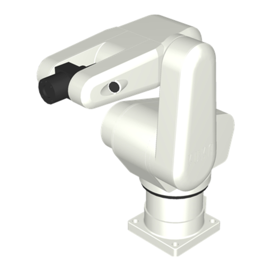
An F3 system: computer, teach pendant, controller, and arm. The F3 robot is run by a program that can be developed either on the controller with a terminal or teach pendant, or off-line on a computer using Robcomm 3 or equivalent tools. -
Page 20: Component Parts
F3 Robot Arm User Guide Component Parts Before installing the robot system, locate and check that you have received all the components. • If you did not order options, the robot system is packaged in two containers. • Options may be shipped in separate containers and may include: gripper, teach pendant, user guides, diskette(s), cable extensions, spares, etc. -
Page 21: F3 Arm
Chapter 2: Introduction F3 Arm The F3 robot arm has six rotational degrees of freedom. This allows it to move a gripper or any other tool of choice to the desired location defined by three coordinates for position in the workcell and three coordinates (angles) for orientation at that position. -
Page 22: Umbilical Cable
F3 Robot Arm User Guide Umbilical Cable An umbilical cable connects the F3 arm to the C500C controller. Inside the cable, there are two optical fibres (for communications between the robot and controller) and five copper conductors (for +12VDC, 2 x +24VDC, +77VDC and two ground lines) enclosed inside a black polyurethane jacket. -
Page 23: F3 Options
Chapter 2: Introduction F3 Options The following F3 options are available from CRS or an authorized distributor. Off-Robot Hardware • teach pendant • track • long umbilical cable • long teach pendant cable • GPIO termination block • external +24 V power supply for GPIO •... -
Page 24: End-Of-Arm I/O
• Early F3 robots are equipped with end of arm I/O boards, which control the solenoid but not the servo gripper. Users with this version of the robot wishing to add a servo gripper should contact sales or customer support group at CRS. -
Page 25: Chapter 3
This chapter provides a brief guide to designing a safe workcell, including some considerations for safeguarding the workcell and precautions for the safe use of the F3 robot system. It is recommended that the system integrator and the end user be aware of the robotic safety standards currently applicable. -
Page 26: Safety Principles In Operating Robots
F3 Robot Arm User Guide Safety Principles in Operating Robots In the design of the F3, careful consideration was given to safety; however, risks associated with the operation of robot systems can only be minimized and not eliminated. System integrators and end-users have the responsibility of assessing these risks and providing additional safeguarding measures in the workcell. -
Page 27: F3 Safety Features
Chapter 3: Safety Precautions F3 Safety Features The safety measures implemented by CRS include: 1. hard-stops in joints 1 to 5 to restrict its range of motion; 2. a Cartesian speed limit of 250 mm/s when the teach pendant is used in manual mode;... -
Page 28: Known F3 Hazards
F3 Robot Arm User Guide Known F3 Hazards 1. The space between moving linkages of the robot introduces a crushing/pinching hazard; these are labeled as pinch points on the robot. 2. System operation is not affected in any way by failure of the amber arm- power light. -
Page 29: Safeguards And Safety Measures In Workcell Design
Chapter 3: Safety Precautions Safeguards and Safety Measures in Workcell Design Safeguards may include, but are not limited to, fixed barriers, interlock barriers, perimeter guarding, awareness barriers, and awareness signals. Incorporate safety measures into your work cell design to reduce the risk of hazard. -
Page 30: Emergency Stops (E-Stops)
When arm power is removed, fail-safe brakes engage to prevent the robot from moving due to gravity or inertia. The F3 robot has a category 0 e- stop (as defined by the European standard EN 418). This is classed as an uncontrolled stop, since power is immediately removed from the robot motors and brakes are engaged on the main drive axes. -
Page 31: Presence Sensing Interlocks
Chapter 3: Safety Precautions Example of typical barriers and remote E-Stops. Pressing an e-stop does not turn off power to the controller. Processes that are running on the controller continue to run, except for those (without structured exception handling or other error checking) requiring robot motion, which will terminate when arm power is removed. - Page 32 F3 Robot Arm User Guide Presence sensors include: • Contacts on doors • Light curtains • Pressure-sensitive floor mats Example of barriers and interlocked contacts on doors All presence-sensing devices should be designed and constructed to fail safe in the event of a component failure. Also, the design should place the presence-sensing envelope far enough from the arm so that arm motion stops before the intruder reaches the arm workspace.
- Page 33 Chapter 3: Safety Precautions Example of barriers and interlocked pressure mats Example of barriers and interlocked light curtain. 99-05-31...
-
Page 34: Other Safety Measures
F3 Robot Arm User Guide Other Safety Measures In addition to physical barriers, e-stops and presence sensors, safety measures can include, but are not limited to: • Awareness signals An awareness signal is an audio or visual alarm, such as a buzzer or light, activated by a sensor in a larger envelope outside the inner e-stop connected envelope. -
Page 35: Environmental Requirements
The robot has not been rated for operation in an environment of excessive vibration or impact. Electromagnetic Interference The F3 robot has been tested to the European EMC requirements, and meets the industrial rating. The robot should not be exposed to excessive electrical noise or plasma. -
Page 36: Power Requirements
7/8/16 A Power System Grounded, Single Phase Maximum Power 1000 VA Other Energy Sources The F3 robot has provision for actuating pneumatic tooling. The following table specifies the pneumatic requirements. Specification Value Air pressure, maximum 6.89 Bar, 6.89 kPa, 100 psi... -
Page 37: Power Distribution
Failure to provide a grounded AC input may result in electric shock, and damage to the controller. The F3 Robot must be mounted on a station, which is grounded to the same voltage potential as that of the controller ground. Failure to do so may result in the risk of fire due to the high currents that may flow in the chassis ground line of the umbilical cable as a result of the difference in ground potential. -
Page 38: Cables And Circuitry
F3 Robot Arm User Guide Cables and Circuitry • The umbilical cable should be routed out of the path of vehicle traffic (e.g. forklifts) and people. Damage to the fibre optics will occur if sufficient pressure is applied to the cable. -
Page 39: Robot Handling
A recommended position is the packing position, which can be reached by running the \diag\f3pack command from any shell. In earlier versions of the F3, this was \diag\pack. In the earliest versions, this was pack. Alternatively, if robot power is off, but the controller is still attached, use the brake release switches and move the robot into a more suitable position before moving it. -
Page 40: Live Ac Power
F3 Robot Arm User Guide Live AC Power Disconnect the AC power cord from the controller when accessing the inside of the controller. The controller should only be opened by trained personnel. Electrically Conductive and Live Objects • Do not allow electrically conductive objects or any liquid to come into contact with the controller circuitry. -
Page 41: Operator Safety
Operator Training Ensure that personnel who program, operate, maintain or repair the robot are adequately trained and demonstrate competence to perform their jobs safely. Attend a CRS training course for proper training. Ensure that operators: • are familiar with the safety precautions stated in this chapter •... -
Page 42: Safety And Operation Checks
F3 Robot Arm User Guide Safety and Operation Checks Ensure that you have followed all the instructions supplied within this manual. BEFORE applying power to the arm, verify that: • the robot is properly installed, mounted, and is stable. Refer to page 53 for mounting and installation procedures. -
Page 43: Working Within The Robot's Workspace
Chapter 3: Safety Precautions Working Within the Robot’s Workspace Activities covered in this section require personnel to be in the restricted space of the robot while arm power is on. Before entering within the robot’s workspace, perform the following checks and safety precautions: •... - Page 44 F3 Robot Arm User Guide 99-05-31...
-
Page 45: Chapter 4
C H A P T E R 4 Specifications This chapter describes the following characteristics about the F3 robot arm: • Physical Characteristics • Dimensions • System Control • Robot Performance • Workspace • Reach • Torque Ratings • Joint Speeds and Acceleration Rates •... -
Page 46: Physical Characteristics
F3 Robot Arm User Guide Physical Characteristics F3 Arm Weight • 53 kg [115 lb] Reach • 710 mm [28 in] from joint 1 axis to tool flange Configuration • Articulated • Six degrees of freedom Motor • DC brushless motors Transmission •... -
Page 47: Dimensions
Chapter 5: Installation Dimensions The dimension of each joint is measured from axis to axis. Section Dimension Base (mounting surface) to shoulder 13.8 Shoulder offset (horziontal displacement from J1 axis to J2 axis) Shoulder to elbow 10.4 Elbow to wrist pivot 10.6 Wrist pivot to tool flange 99-05-31... -
Page 48: System Control
F3 Robot Arm User Guide System Control • CROS - multi-tasking operating system Software • RAPL-3 - programming language • Joint angles Robot Location • Cartesian (X, Y, Z, Z-rot, Y-rot, X-rot) Representation • Variable tool transform • Variable base offset compensation •... -
Page 49: Robot Performance Summary
Chapter 5: Installation Robot Performance Summary Payload • 3 kg (6.6 lb) Reach • 710 mm [28 inch] nominal • 810 mm with gripper Joint Speed • Joint 1 - 240 °/s • Joint 2 - 210 °/s • Joint 3 - 240 °/s •... -
Page 50: Workspace
(ISO 9946). The following diagrams define the F3 workspace calculated from the wrist reference point. The work envelope of the F3 arm: plan view (dimensions in mm.) The work envelope calculated from the wrist reference point (dimensions in mm.). 99-05-31... -
Page 51: Reach
The maximum reach of the arm is calculated horizontally forward and backward from the waist axis and vertically upward from the bottom of the base. The arm can reach points below the level of the bottom of the base. F3 Maximum Arm Reach Horizontal Forward to tool flange 710 mm [27.9 in]... - Page 52 F3 Robot Arm User Guide Reach of F3 with servo gripper (dimensions in inches [mm]) 99-05-31...
-
Page 53: Torque Ratings
Chapter 5: Installation Torque Ratings Arm Torque The torque rating for each arm joint is defined in the following table. Continuous Stall Torque Rating Joint Axis Torque in-lb. Waist 74.5 Shoulder 74.5 Elbow 74.5 Wrist rotate 16.6 Wrist pitch 16.6 Tool roll 16.6 Wrist Thrust and Torque... -
Page 54: Motion Specifications
F3 Robot Arm User Guide Motion Specifications The following tables list the speed and acceleration ratings of the F3 robot. Speed at End-Effector Maximum Speeds Motion Compounded joint interpolated motions 3.9 m/sec Average pick and place cycle time 1.2 sec... -
Page 55: Slew Time
Chapter 5: Installation J2 Acceleration De-rating Curve 1500 1200 payload (kg) J3 Acceleration De-rating Curve 1500 1200 payload (kg) J5 Acceleration De-rating Curve 2000 1500 1000 payload (kg) Slew Time Slew time is defined as the rate at which the arm can be driven from limit to limit over a dynamic range. - Page 56 F3 Robot Arm User Guide Minimum Slew Time For Each Joint Axis Slew Angle Max. Acceleration Max. Speed Slew Time Slew Speed ° ° ° ° ° ° ° ° /s ° ° ° ° /s ° ° ° ° /s...
-
Page 57: Resolution
Chapter 5: Installation Resolution Resolution is the smallest increment of motion or distance that can be detected or controlled. Arm resolution is dependent upon the distance between the center of the tool flange surface and the center of gravity of the payload, as shown in the rotational and positional tables. -
Page 58: Load
This includes the gripper and any payload that it carries. The following de-rating curves depict the variation of the payload capacity of the F3 robot with distance from the tool flange and axis. Payload De-rating 3 kg... -
Page 59: System Features
Absolute Encoders Principles of Operation Absolute encoders are used in the F3 robot. Their design is based on using a low resolution gray scale disk in conjunction with a high resolution incremental disk to detect absolute position within one turn. -
Page 60: Arm Power Light
Chain Tensioners In additional to harmonic drives on all joints, the F3 robot also has chain drives on joints 2, 3 and 5. These chains are held in tension by nonlinear springs which roughly maintain the required tension even if the chains stretch over time. -
Page 61: Embedded Control And Power Electronics
Pneumatic Valve A double-actuation pneumatic valve is provided in the default configuration of the F3 system and maintains the state of an air-driven tool even after controller power is shut down. This mechanism is controlled by the SGIO board and supplied by an internal 3 mm air line. The outlets at the air manifold are designed for 3 mm lines. - Page 62 F3 Robot Arm User Guide contains the circuit which sinks the power generated when any of the six motors decelerates rapidly (a phenomenon known as degenerative braking). Fibre Board The fibre board converts the optical signals from the umbilical cable to...
-
Page 63: Chapter 5
C H A P T E R 5 Installation This chapter describes how to: 1. Unpack the robot system. 2. Mount the robot arm. 3. Mount the controller. 4. Connect the umbilical cable. 5. Install the AC fuses and voltage selector. 6. -
Page 64: Unpacking The F3 System
Keep the system together The arm and controller you have received have been fine-tuned and burned- in together as a single system. If you have purchased multiple F3 systems, do not randomly mix and match controllers and robots. Serial numbers The serial numbers for the arm and for the controller are printed on the plates attached to the arm and to the controller. -
Page 65: Lifting The Arm
Chapter 5: Installation Lifting the Arm 1. Ensure that the workcell mounting platform is ready and cleared of any debris. 2. Carefully lift the arm from the crate to your workcell mounting platform. 3. Unscrew the eyebolt from the upper bolt hole of the shoulder casting and screw it securely into the lower bolt hole on the front of the shoulder casting. -
Page 66: Collecting The Shipping Materials
F3 Robot Arm User Guide Collecting the Shipping Materials Keep all shipping materials. Warning! Do not use the shipping cap screws to fasten the arm in your workcell. The cap screws used to ship the arm are 5/16 inch cap screws. They are not adequate to fasten the arm in the workcell. -
Page 67: Mounting The Arm
Chapter 5: Installation Mounting the Arm The arm should be firmly mounted on a supporting platform rigid enough to support the arm and to withstand inertial forces during acceleration and deceleration. Positioning the Arm Install the arm in either an upright position (mounted on a table top or pillar) or an inverted position (suspended from overhead brackets). -
Page 68: Mounting Platform
F3 Robot Arm User Guide Inverted Configuration When the arm is in the inverted configuration, a greater portion of the table surface is available as workspace. When using this configuration, a base offset is strongly recommended. See the RAPL-3 manuals for more information. -
Page 69: Preparing A Mounting Platform
3. Secure the arm to the platform with 4 x M12 x 1.75 x 50 mm long, stainless steel 18-8 (A2), hex socket cap screw. A mounting kit consisting of these fasteners and dowel pins is available from CRS. 99-05-31... - Page 70 F3 Robot Arm User Guide 99-05-31...
-
Page 71: Connecting The Umbilical Cable
Chapter 5: Installation Connecting the Umbilical Cable The umbilical cable connects the controller to the robot arm. Before you begin: • Ensure that the controller main power switch is off. • Ensure the location for the cable is protected and does not leave the cable exposed to damage. -
Page 72: Grounding The System
Failure to provide a grounded AC input may result in electric shock, and damage to the controller. The F3 Robot must be mounted on a station which is grounded to the same voltage potential as that of the controller ground. Failure to do so may result in the risk of fire due to the high currents that may flow in the chassis ground line of the umbilical cable as a result of the difference in ground potential. -
Page 73: Chapter 6
C H A P T E R 6 Customizing Installations This chapter discusses how to add features to the F3 system including: • Installing a Tool on the Robot. • Connecting a Hose to the Pneumatic Port. 99-05-31... -
Page 74: Installing A Tool On The Robot
To make a robot useful, a tool such as a gripper, grinder, deburing tool, etc. must be attached on the face of the robot’s tool flange. The tool flange of the F3 robot is designed to the ISO standard for robot tooling. The drawing shows its relevant dimensions. -
Page 75: Settings Of The F3 Robot's Dual Air Valve Port
Chapter 6: Customizing Installations Settings of the F3 Robot’s Dual Air Valve Port State Port A Port B Notes open closed GRIP_OPEN closed open GRIP_CLOSE power- unknown unknown the power-up state is unknown, however the last state will be maintained... -
Page 76: Connecting A Hose To The Pneumatic Port
F3 Robot Arm User Guide Connecting a Hose to the Pneumatic Port To connect the pneumatic gripper: 1. Screw a barbed fitting into each of the two air ports of the pneumatic connector on the wrist of the robot. 2. At the arm end of the gripper’s air hose, separate the two air hoses for approximately 25 mm. -
Page 77: Chapter 7
C H A P T E R 7 Commissioning the Robot Commissioning is about starting up the robot system and testing it to ensure that it is functioning properly. The procedure should be carried out in the following sequence: 1. Verify Installation. 2. -
Page 78: Verifying Installation
F3 Robot Arm User Guide Verifying Installation Note: Refer to and follow the Safety Operation Checks on page 28 before operating the arm. Checking Arm and Controller Installation Verify that following: • The robot has been mounted securely with four M12 fasteners each with at least 2 cm (0.8”) of thread engagement. -
Page 79: Powering Up The Controller
Chapter 7: Commissioning the Robot Powering Up the Controller During the boot-up sequence of the controller, diagnostic information is displayed at the controller’s front panel hexadecimal display and at the terminal window of Robcomm 3. To check the controller power-up sequence: 1. -
Page 80: Starting The Application Shell On The C500C Controller
F3 Robot Arm User Guide Starting the Application Shell on the C500C Controller Checking and operating the arm is done from an application shell (ash). Initial operation is done from the application named test. To start the application shell: At the $ prompt, enter: ash test The name test can be replaced by that of another application. -
Page 81: Checking All E-Stops
Chapter 7: Commissioning the Robot Checking All E-Stops Use the procedure below to check each E-Stop device to verify that it works. Note: Striking an E-Stop button does not remove power to the servo gripper. As a safety feature, motor power to the gripper is maintained in this situation to not release the payload. -
Page 82: Moving Out Of The Shipping Position
F3 Robot Arm User Guide Moving Out of the Shipping Position The arm is shipped in a position for unpacking and installation. Moving it into a standard configuration will facilitate robot applications. This can be accomplished from an application shell or using the teach pendant. (You may not be ready to use the teach pendant if you have not received training or read the Teach Pendant sections of the Application Development Guide.) -
Page 83: Checking The Live-Man Switch
3. Navigate to a screen for motion by selecting F1 for Edit and, at the next screen, select F3 for Motion. 4. At the Motion screen, use F3 and F4 to scroll through types and modes of motion. Select Velocity and Joint. - Page 84 F3 Robot Arm User Guide 11. Without applying pressure to the live-man switch, press an axis key. The arm should not move and there should be an audible beep indicating that the commanded motion cannot be executed. 99-05-31...
-
Page 85: Chapter 8
C H A P T E R 8 Operating Basics This chapter describes how to operate the robot. Emphasis is placed on F3 specific topics, namely: • units • coordinate systems and reference frames • motion modes • system operation. -
Page 86: Units
F3 Robot Arm User Guide Units For the F3 system, the default unit of distance is the millimeter (mm). To change units in a RAPL-3 system, use the command /diag/setup. For further information, see the Application Development Guide and RAPL-3 Language Reference Guide. -
Page 87: Coordinate Systems And Reference Frames
Addison and Wesley Publishing Company), or contact the CRS Sales Department to inquire about training. In general, commanding the F3 robot to move is no different than with other CRS robots. However, one significant distinction is the definition of the tool frame which, unlike other CRS systems, follows the ISO convention of aligning the tool z-axis with the default tool axis. -
Page 88: Motion Modes
2,048 encoder pulses for every full turn of a F3 motor. The following table re-states this ratio for every joint and also provides, as an example, the number of pulses equivalent to a +90°... - Page 89 Chapter 8: Operating Basics systems. Programs written for the other systems may therefore not be immediately applied to a F3 robot. 99-05-31...
-
Page 90: System Operation
System Operation Brake Release There are brakes in the three main joints of the F3 robot system to keep these joints in position when arm power or controller power is off. They are released automatically when arm power comes on. -
Page 91: Delay After Turning On Arm Power
Delay after Turning on Arm Power F3 robot motion should only be started 2 seconds after arm power is turned on. In manual operation, this is usually not an issue; however, in a RAPL-3 program, the delay() function should be used after automatic detection of arm power. - Page 92 F3 Robot Arm User Guide 99-05-31...
-
Page 93: Chapter 9
C H A P T E R 9 Troubleshooting This chapter describes the serviceable problems that can occur in the F3 Robot System. Only non-invasive or minimally invasive procedures are described here. Any inspection or remedial procedure requiring major disassembly is given in the F3 Service Guide. -
Page 94: Arm Power Failure
F3 Robot Arm User Guide Arm Power Failure If arm power does not come on when the switch is pressed (either the arm power LED on the controller front panel or the flashing amber light on the robot, or both, remain off), check for the following conditions and perform the corrective action. -
Page 95: Amplifier Communications Failure
The F3 servo network consists of the two amplifier modules as well as the SGIO board which controls the end-of-arm tool (air or servo gripper) and the end–of-arm I/O channels. To assess the extent of the network failure, command the gripper to open or close. -
Page 96: F3 Calibration & Re-Homing
In F3 robot systems released in late 1997 and first part of 1998, the calibration file is generically named robot.cal during factory burn-in. In newer systems, the serial number of the robot is used as the file name - e.g. - Page 97 4. Manually back-drive the robot to align the calibration markers. (In some F3 robots, the marker is a pair of triangles on either side of a joint. The user should line up the opposing vertices of the triangles. Other robots have markers with a triangle on one side and a small alignment band on the other.)
- Page 98 F3 Robot Arm User Guide 99-05-31...
-
Page 99: Chapter 10
C H A P T E R 1 0 Preventive Maintenance This chapter covers the preventive maintenance necessary to keep the F3 system running trouble free. All the procedures outlined in this chapter are of a non-invasive or minimally invasive nature. In other words, there is no need to disassemble the robot beyond removal of fasteners or covers. -
Page 100: Regular Inspection
0.2” and 0.1” from the lip of the cup. Drawing showing important parts of chain tensioner The chain tensioners in the F3 robot have been designed to tighten the chain evenly so that the change at the output sprocket is minimized as tension is increased. -
Page 101: After Collision
Chapter 10: Preventive Maintenance Repeatability Check The repeatability specification of any industrial robot is typically based on testing under controlled conditions. In practice, it may vary according to environmental conditions such as temperature fluctuations. It is a good practice to set up a mechanism in your workcell to periodically verify the repeatability of the robot. -
Page 102: Lubricating The Chain
CRS Robotics Corp. cannot provide assurance that any other lubricant will be suitable for the chains or will not be harmful to other F3 components. If you are using the CRS-recommended lubricant which comes in a pressurized can, squirt once gently instead of adding 5 drops. -
Page 103: Re-Lubricating Joint 3
9. Allow lubricant to drain while the other chains are re-lubricated. Re-lubricating Joint 3 To re-lubricate the joint 3 chain for an upright F3 robot: 1. Remove the four stainless M4 machine screws from the lower link. 2. Rotate joint 2 to -90° (so that the lower link is horizontal). In this configuration, the two top openings are for adding lubricant and the bottom two are for drainage. -
Page 104: Replace And Update
F3 Robot Arm User Guide 10. Add another 3 drops of lubricant through the opening on top. 11. Rotate joint 3 to 0° so that the wrist is vertically up or close to it 12. Rotate joint 5 to +90°. -
Page 105: Battery Maintenance
Battery Maintenance Background The absolute encoders of the F3 robot rely on battery power to maintain multi-turn data when it is not connected to a live controller - i.e. the controller is turned off or the umbilical cable is disconnected at one or both ends. -
Page 106: Extended Shutdown
Six Month Battery Check Even if you do not plan to shut down the F3 system, you should verify the battery voltage six months after receiving the robot. •... -
Page 107: Log Update
You have up to ten (10) minutes to carry out the above steps before the encoders are no longer active and calibration is lost. Log Update After verifying or replacing the batteries in your F3 system, record the maintenance activity in the maintenance log. 99-05-31... -
Page 108: Chain Replacement
F3 Robot Arm User Guide Chain Replacement Chains need to be replaced after 18 months of use or sooner if the load and duty cycle of the application are high. Contact our Customer Support Group to determine the best schedule for chain inspection and replacement for your application. -
Page 109: Harmonic Drive Lubrication
Chapter 10: Preventive Maintenance Harmonic Drive Lubrication CRS Robotics Corp. uses and recommends the 4B no. 2 grease from HD Systems for the harmonic drives. This is an efficient and durable grease; it is not necessary to add new grease to the harmonic drives prior to changing it. -
Page 110: Wire Harness Replacement
F3 Robot Arm User Guide Wire Harness Replacement There are four moving wire harnesses within the F3 robot: • joint 1 harness • lower link harness • joint 4 harness • wrist harness. Like other mechanical components, copper conductors may fail after a high number of cycles of motion. -
Page 111: Cleaning The Robot System
Chapter 10: Preventive Maintenance Cleaning the Robot System All exterior arm surfaces can be cleaned using house-hold cleaning products provided care is taken not to allow such products to seep into the robot interior through any seam. Special attention is required when cleaning the wrist area near the wrist amplifier and the waist area near the waist amplifier. - Page 112 F3 Robot Arm User Guide 99-05-31...
-
Page 113: Umbilical Cable Connector
A P P E N D I X A Umbilical Cable Connector The connector used in the construction of the umbilical cable is an industrial connector, with an ingress protection rating of IP65. The cable is wired straight through, with no pins swapping position. Pin on Pin on Signal Name... - Page 114 F3 Robot Arm User Guide 99-05-31...
-
Page 115: System Fuses
A P P E N D I X B System Fuses The controller has fuses installed to protect various subsystems in the case of short circuit faults. AC fuses (located in power entry module with AC power cord). System Voltage Fuse Rating Type Size... - Page 116 F3 Robot Arm User Guide 99-05-31...
-
Page 117: Glossary
Glossary application A collection of software and hardware that allows the robot to accomplish a particular task or job. Typically, a robot application consists of robot hardware, other hardware of the workcell, and a robot program with its file of locations and other variables. - Page 118 F3 Robot Arm User Guide origin of the world cartesian coordinate system relative to the center of the mounting surface of the arm. See: world frame of reference. cartesian coordinate system A system for defining space based on three linear perpendicular axes: X, Y and Z.
- Page 119 The independent motion in which the arm can move its end effector (gripper, tool). In an articulate arm, the number of independent joints. For example, the F3 has six degrees of freedom. directories The default directory where the installation utility installs Robcomm 3 is...
- Page 120 A point in space known to the robot. With a CRS robot, a location can be one of two types of locations. A cartesian location (cloc) stores information according to a cartesian (straight-line axes meeting at right angles) coordinate system. A precision location (ploc) stores information according to pulse counts of the joints of the robot arm.
- Page 121 The person who programs or re-programs the robot to do tasks. See also: operator, system integrator. RAPL (robot automation programming language) The language used to program CRS robots. RAPL-3 has a completely different architecture from RAPL-II. RAPL-3 A high-level, block-structured, compiled language, similar to C, introduced in 1997.
- Page 122 F3 Robot Arm User Guide reach The maximum distance that the arm can extend the tool flange or gripper. Reach defines the work envelope. repeatability The ability of the robot to repeat the same motion or position a tool at the same position when presented with the same control signals (over repeated cycles).
- Page 123 Glossary the information about the position and store it in the location variable. When the information is stored, the location is taught. All taught locations are stored in a .v3 file. See also: location, .v3 file. terminal An arrangement that allows command line access to CROS on the controller. To communicate with CROS on a C500 or C500C controller, the terminal window of Robcomm 3, any terminal emulator, or a simple serial terminal, can be used.
- Page 124 F3 Robot Arm User Guide tool tip A physical reference point on a tool, typically the end. tool transform A modification to the tool frame of reference that places the origin of the frame to be at a place other than the centre of the surface of the tool flange.
- Page 125 Glossary .v3 file A file that stores locations and other teachable variables. Each instrument has its own .v3 file that stores the locations for that instrument. The .v3 file is stored in the instrument’s directory of the app/ directory of the CROS file system.
- Page 126 99-05-31...
-
Page 127: Index
Index absolute encoders, 45 electrostatic discharge protection, Address of CRS Robotics, vi air supply, 62 E-stops, 16 amplifier communications failure, e-stops, check, 67 F3 options, 9 amplifier modules, 47 gripper hose, 62 application shell, start, 66 gripper, OPEN/CLOSE, 62 arm configuration, 32... - Page 128 F3 Robot Arm User Guide troubleshooting, 79 unpacking, 50 umbilical cable connector, 99 weight, arm, 32 umbilical cable properties, 8 wrist thrust and torque, 39 99-05-31...
Need help?
Do you have a question about the F3 and is the answer not in the manual?
Questions and answers