
Related Manuals for Sismo SimCard SC-MB Series

Summary of Contents for Sismo SimCard SC-MB Series
- Page 1 SimCard Motherboard Ethernet and Daughterboards User Manual SC-MAN-SCE-E-10-0004 Rev. 1.4 ©2005-2017, Sismo Soluciones All rights reserved...
-
Page 2: Table Of Contents
Flight Simulation www.sismo-soluciones.com Rev. Date Description April 2010 First Edition February 2013 Changes February 2014 Ethernet Version July 2017 Template, modifications, FAQs. INDEX Definitions and acronyms .......................... 4 Definitions ............................4 Acronyms ............................4 Purpose of this Document ......................... 5 Features .............................. - Page 3 Flight Simulators Solutions www.sismo-soluciones.com Simcard 32 dispay daughter board (SC-32DISP-DB) ............... 24 6.5.1 Wiring Schedule .......................... 25 Simcard 10 analog input daughter board (SC-10AL-DB) ..............26 6.6.1 Supported Components ......................27 Fast interface and interconnection card (GIC) ................27 Typical use of the simcards ........................27 Flight simulator use .........................
-
Page 4: Definitions And Acronyms
A device for connecting many Ethernet cables. For use when you want to connect many Ethernet devices to a single computer. SC Pascal A programming language and a high level editor/compiler. All script provided by Sismo are programmed in this language. There are manuals for learning this language on our website. -
Page 5: Purpose Of This Document
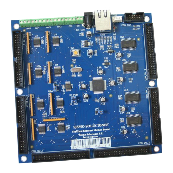
Welcome to one of the boards of the SimCards family named SC-MB, specially designed for the control and management of inputs and outputs of equipment and modules of simulators made or not by Sismo. Also they can be used to any other system that requires to control a few elements on real time. -
Page 6: The Family Of Simcards Sc-Mb Boards
Flight Simulators Solutions www.sismo-soluciones.com We have named the group formed by the Mother Board and the types of Daughter Boards which can be connected to it: “the family of SimCards SC-MB boards”. The SC-MB Ethernet Family. They are controlled by means of the programming language SC Pascal, the code it can be downloaded for free. -
Page 7: Daughter Boards You Can Connect To The Sc-Mb
Flight Simulators Solutions www.sismo-soluciones.com There are two customizations of this product. You can choose to purchase the version with or without displays. There is also an option of having the “Bottom pins” version, this has been designed to connect directly to a backpanel and the connectors are located on the opposite side of the board. -
Page 8: Supported Components
Flight Simulators Solutions www.sismo-soluciones.com SUPPORTED COMPONENTS The components which can be connected to this board are all kinds of switches, push-buttons, rotaries, encoders, LEDs, displays, RELAYs, etc. The most common components are: Rotary Encoders Switch Buttons Push Buttons Rotary Switch... -
Page 9: Wiring Schedule
Flight Simulators Solutions www.sismo-soluciones.com WIRING SCHEDULE The SC-MB is equipped with two IDC connectors of 40 pins for the inputs, DI1 and DI2; two IDC connectors of 40 pins for Outputs, DO1 and DO2. There are also two IDC connectors with 40 pins for the Displays, DY1 and DY2. - Page 10 Flight Simulators Solutions www.sismo-soluciones.com 5.5.1.2 DI2 Controls inputs 33 to 64. All the grounds are common. Function Function State State Input 33 Input 34 Input 35 Input 36 Input 37 Input 38 Input 39 Input 40 +5V cc Input 41...
-
Page 11: Outputs
Flight Simulators Solutions www.sismo-soluciones.com 5.5.2 Outputs The Mother Board has a total of 64 outputs in a common cathode configuration which are distributed in two connectors of 40 pins each. The scheme of connection in common cathode format for the connection of leds is shown in this image. - Page 12 Flight Simulators Solutions www.sismo-soluciones.com 5.5.2.2 DO2 Connector is for outputs 33 to 64. All the grounds are common. Function Function State State Output 33 Output 34 Output 35 Output 36 Output 37 Output 38 Output 39 Output 40 +5V cc...
-
Page 13: Displays
Flight Simulators Solutions www.sismo-soluciones.com 5.5.3 Displays The Mother Board has a total of 32 displays of 7 segments of common cathode which are distributed in two 40 pins IDC connectors. If you purchase the SC-MB without displays; DY1 and DY2 will be missing. - Page 14 Flight Simulators Solutions www.sismo-soluciones.com 5.5.3.2 DY2 is a 40 pin connector which can control 16 displays of 7 segments. Named display 17 to 32. All the grounds are common. Function Function Segment A Segment B Segment C Segment D Segment E...
-
Page 15: Daughterboards
Flight Simulators Solutions www.sismo-soluciones.com DAUGHTERBOARDS SIMCARD 64 DIGITAL INPUT DAUGHTER BOARD (SC-64DI-DB) This board is connected by means of a flat cable of 10 wires to the Mother Board. Each board has 64 digital inputs and 2 boards of this type can be connected to the Mother Board. -
Page 16: Wiring Schedule
Flight Simulators Solutions www.sismo-soluciones.com 6.1.2 Wiring Schedule There are two 40-pin IDC Connectors on this board. The sockets are called DI1 and DI2. DI1 controls the discreet inputs 1 to 32. DI2 controls inputs 33 to 64. All the grounds in these connectors are common. - Page 17 Flight Simulators Solutions www.sismo-soluciones.com 6.1.2.2 Function Function State State Input 33 Input 34 Input 35 Input 36 Input 37 Input 38 Input 39 Input 40 +5V cc Input 41 Input 42 Input 43 Input 44 Input 45 Input 46 Input 47...
-
Page 18: Simcard 64 Digital Output Daughter Board (Sc-64Do-Db)
Flight Simulators Solutions www.sismo-soluciones.com SIMCARD 64 DIGITAL OUTPUT DAUGHTER BOARD (SC-64DO-DB) This board is connected by means of a flat cable of 10 wires to the Mother Board. Each board has 64 digital outputs and 2 boards of this type can be connected to the Mother Board. - Page 19 Flight Simulators Solutions www.sismo-soluciones.com 6.2.2.1 Function Function State State Outputs 01 Outputs 02 Outputs 03 Outputs 04 Outputs 05 Outputs 06 Outputs 07 Outputs 08 +5V cc Outputs 09 Outputs 10 Outputs 11 Outputs 12 Outputs 13 Outputs 14 Outputs 15...
- Page 20 Flight Simulators Solutions www.sismo-soluciones.com 6.2.2.2 Function Function State State Output 33 Output 34 Output 35 Output 36 Output 37 Output 38 Output 39 Output 40 +5V cc Output 41 Output 42 Output 43 Output 44 Output 45 Output 46 Output 47...
-
Page 21: Simcard 64 Dio (32 Digital Input / 32 Digital Output) - Daughter Board (Sc-64Dio-Db)
Flight Simulators Solutions www.sismo-soluciones.com SIMCARD 64 DIO (32 DIGITAL INPUT / 32 DIGITAL OUTPUT) - DAUGHTER BOARD (SC- 64DIO-DB) This board is connected by means of a flat cable of 10 wires to the Mother Board. Each SC has 32 digital inputs and 32 digital outputs. -
Page 22: Wiring Schedule
Flight Simulators Solutions www.sismo-soluciones.com 6.3.2 Wiring Schedule There are two 40-pin IDC Connectors on this board. The sockets are called P-IN and P-OUT. P-IN controls the inputs 1 to 32. P-OUT controls outputs 1 to 32. All the grounds in these connectors are common. - Page 23 Flight Simulators Solutions www.sismo-soluciones.com 6.3.2.1 Connector P-OUT Function Function State P-OUT State Outputs 01 Outputs 02 Outputs 03 Outputs 04 Outputs 05 Outputs 06 Outputs 07 Outputs 08 +5V cc Outputs 09 Outputs 10 Outputs 11 Outputs 12 Outputs 13...
-
Page 24: Simcard 14 Servos Daugther Board (Sc-14Serv-Db)
Flight Simulators Solutions www.sismo-soluciones.com SIMCARD 14 SERVOS DAUGTHER BOARD (SC-14SERV-DB) This board is connected by means of a flat cable of 10 wires to the Mother Board. Each board can control 14servos and a single board of this type can be connected up to the Mother Board. -
Page 25: Wiring Schedule
Flight Simulators Solutions www.sismo-soluciones.com This board supports any type of seven segment displays in the common cathode configuration. 6.5.1 Wiring Schedule There are two 40 pin IDC Connectors which can be used to control 32 displays. The sockets for these connectors are called DY1 and DY2. DY1 controls the 7 segment displays from 1 to 16. -
Page 26: Simcard 10 Analog Input Daughter Board (Sc-10Al-Db)
Flight Simulators Solutions www.sismo-soluciones.com 6.5.1.2 Function Function Segment A Segment B Segment C Segment D Segment E Segment F Segment G Common GND Common GND Display17 Display18 Display19 Display20 Display21 Display22 Display23 Display24 Common GND Common GND Segment A Segment B... -
Page 27: Supported Components
You don’t need to use Sismo modules to benefit from the use of these control boards, any bought or home- made module is compatible. These boards work well in conjunction with GICs (General Interface Card), which make wire connection problems a thing of the past. -
Page 28: Connection
CONNECTION When following our connection map you can use the free script provided by Sismo. In case of modifying or using a customized solution, you will have to program your own script. -
Page 29: Other Applications
They are recommended when you already have modules from another provider or self-made, as with the green connectors you will be able to easily connect single wires or adapt your connection map to Sismo Soluciones. Here is a list of GIC boards you would need to make a customized connection to each Backpanel: Device Electronic Version PLUG &... -
Page 30: Faq
IDC Connectors with a codename which easily identifies the module you need to connect. You do not need to purchase a backpanel, but if you are building your own custom modules with Sismo products, a backpanel is a very helpful and professional solution. -
Page 31: Related Products
#What is the difference between common cathode and common anode? By default, all of Sismo’s products are prepared in common cathode. LEDs have polarity, if this polarity is inversed, the LEDs don’t work. In common cathode, all of the LEDs share a positive node, whereas in common anode, they share a negative node.
Need help?
Do you have a question about the SimCard SC-MB Series and is the answer not in the manual?
Questions and answers