Table of Contents

Summary of Contents for gAvilar gAVC 1200 N
- Page 1 GA-02.029-EN-03-05-2018 gAVC 1200 Installation Manual.docx gAVC 1200 N and gAVC 1200 NP Gas Volume Converter GA-02.029-EN-03-05-2018 Installation Manual Rev. 03 Please look at our homepage www.gavilar.nl for the latest version of the document.
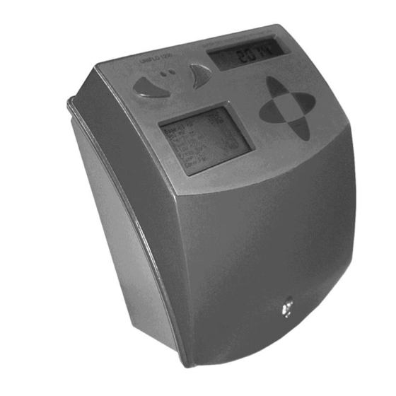
- Page 2 GA-02.029-EN-03-05-2018 gAVC 1200 Installation Manual.docx gAVC 1200 N and gAVC 1200 NP overview IR-interface Standard display Graphic display Keypad (4 scrolling buttons) Label DIP-switches (hardware password setting) Metrologic seal Metrologic seal Power supply Battery Option board connection bar Terminals Cable glands Cable mounting brackets GA-02.029-EN-03-05-2018 rev.03...
-
Page 3: Table Of Contents
2.2 At delivery ............................7 2.3 gAVC Config............................7 3.0 General recommendations ..................8 4.0 Installation ........................8 4.1 Mounting gAVC 1200 N/NP ........................ 9 4.2 Wire connection ..........................10 4.2.1 Choice of wires: ..........................12 4.2.2 Earthing ............................12 4.3 Temperature sensor .......................... - Page 4 GA-02.029-EN-03-05-2018 gAVC 1200 Installation Manual.docx 8.4 Temperature sensor .......................... 28 8.5 Inputs and outputs ..........................29 8.5 Communication ..........................30 9.0 Applicable standards ....................30 10.0 Disposal of the product after end of use............... 30 GA-02.029-EN-03-05-2018 rev.03 Page 4 of 31...
-
Page 5: General
1.0 General 1.1 Introduction The gAvilar gAVC 1200 N and gAVC 1200 NP Gas Volume Converter, is one unit out of a series of new generation High-End PTZ converters. The unit is designed with special emphasis on simple operation and low maintenance. -
Page 6: Definitions
GA-02.029-EN-03-05-2018 gAVC 1200 Installation Manual.docx B. User part The battery compartment, which contains the connecting board with terminals, input/outputs, serial link and the power supply connection terminal. The standard gAVC system also include: - Wall mounting bracket - A pressure sensor with 3 m cable - A Pt1000 temperature sensor with 3 m cable C. -
Page 7: Unpacking
2.3 gAVC Config. A special software program is developed for setting up and reading of the gAVC 1200 N/NP. This program is called gAVC Config. The program can be downloaded from the gAvilar website. Once installed, the integrated Help File is a useful tool. -
Page 8: General Recommendations
3.0 General recommendations Environment: The gAVC 1200 N/NP is designed with enclosure class IP 65, for limited outdoor installation. However, if the unit is installed outdoor, or in a high humidity environment, it is recommended to use a special housing, suitable for outdoor weather conditions. -
Page 9: Mounting Gavc 1200 N/Np
GA-02.029-EN-03-05-2018 gAVC 1200 Installation Manual.docx 4.1 Mounting gAVC 1200 N/NP Wall mounting The instrument is for vertical mounting, only (max 40° from vertical). Cable outlet shall be turned downwards. The gAVC unit is mounted on the wall with the mounting bracket and sealing plate. At delivery the mounting bracket and sealing plate is factory mounted. -
Page 10: Wire Connection
GA-02.029-EN-03-05-2018 gAVC 1200 Installation Manual.docx 4.2 Wire connection Terminals Power supply (option) Power input Not used INaINb IN GND 6 GND Pressure Temp Pulse Alarm Pulse 1 Pulse 2 Alarm sensor input Serial Sensor input Output Output Output EEx- Earth Earth connections Serial A + Serial b (Uniwire) Alarm output... - Page 11 GA-02.029-EN-03-05-2018 gAVC 1200 Installation Manual.docx Special requirements in hazardous area: See chapter 5. Terminal and wire description Analogue terminals Pressure sensor 1 Pressure sensor supply - White Pressure sensor 2 Pressure sensor temperature out Blue Pressure sensor 3 Pressure sensor, pressure signal out Yellow Pressure sensor 4 Pressure sensor supply +...
-
Page 12: Choice Of Wires
GA-02.029-EN-03-05-2018 gAVC 1200 Installation Manual.docx 4.2.1 Choice of wires: General: Cable diameter of min - max: 4mm - 7mm – 2.5 mm Cable cross section min - max: 0.14 mm Wire insulation min: 0.25mm (When installed in hazardous areas) When installed in hazardous areas the wire insulation of min. 0.25 mm has to be checked. Recommended types: Soft cables: LiYCY 0.25 to 0.5mm , for measurement etc. -
Page 13: Temperature Sensor
GA-02.029-EN-03-05-2018 gAVC 1200 Installation Manual.docx 4.3 Temperature sensor If the temperature sensor is mounted by gAvilar (when delivered), the system is already configured according to the temperature sensor specifications. If the temperature sensor is to be mounted on site, follow the following instructions: - On the temperature sensor cable is attached a label with a bar code. -
Page 14: Pulse Inputs
GA-02.029-EN-03-05-2018 gAVC 1200 Installation Manual.docx 4.5 Pulse inputs There are 2 available LF-inputs on the gAVC 1200 N/NP unit. These inputs can be used separately or as a LF-LF pulse check. This function is configured in the gAVC Config. program. -
Page 15: Alarm Inputs
4.7 Alarm inputs The gAVC 1200 N/NP alarm input is also called a "Tamper alarm". This input can be used for connecting an alarm circuit. The alarm input is set "ON", when the alarm circuit is opened. -
Page 16: Ir-Interface / Permanent Remote Reading Connection
GA-02.029-EN-03-05-2018 gAVC 1200 Installation Manual.docx 4.9 IR-interface / Permanent Remote Reading connection The gAVC 1200 N/NP and the gAVC Config. may be connected in 2 ways: - Via the IR-interface. The IR-interface is attached to the gAVC unit with the built in magnets. -
Page 17: Ex Installation (Atex Scheduled)
When mounting an option board and on battery replacements please also observe the guidelines in the paper "ESD correct handling". It is also important that the gAVC 1200 N/NP is placed so that no direct or indirect heating/cooling is possible outside the specified ambient temperature interval for the gAVC 1200. -
Page 18: Pressure- And Temperature Sensor Cables
GA-02.029-EN-03-05-2018 gAVC 1200 Installation Manual.docx 5.3 Pressure- and temperature sensor cables The pressure and temperature sensor cables are app. 3 meters. Note: Only the supplied cables are allowed in the installation. Do not cut or damage the cable. Damaged cables will result in poor measure precision and poor Ex security. 5.4 Pulse- and alarm outputs These terminals are marked XP3, XP4 and XP5. -
Page 19: Earthing And Connection Of Conducting Cable Screens
5.6 Earthing and connection of conducting cable screens Earth connection: gAVC 1200 N/NP mounted in zone 0 require 3 independent earth connections. Inside the gAVC you will find 2 earth connection terminals. 2 parallel wires 1.5 mm will normally be required (refer to local regulations). -
Page 20: Cable Requirements
Insert new battery, please observe ESD correct mounting. (Only batteries approved by gAvilar) Attention: Use the right battery: gAVC 1200 N for main battery supply, marked “TÜV 18 ATEX 220433 X” use: 94128 gAVC 1200 NP with external power supply and back-up battery, marked “TÜV 18 ATEX 220433 X” use:... -
Page 21: Markings On The Gavc 1200
Externally powered gAVC with option boards Back-up battery and with or without option boards Pulse option board (part of TÜV18 ATEX 220433X) Battery label for gAVC 1200 N Battery label for gAVC 1200 NP GA-02.029-EN-03-05-2018 rev.03 Page 21 of 31... -
Page 22: Option Boards
1200 N/NP earth connection. Those circuits need isolated barriers if leaving the classified zone. Please find the actual demands in the individual installation manuals. gAVC 1200 N/NP is an ex group IIB equipment. Product approved for IIC is allowed for use for IIB but NOT the other way around. -
Page 23: Commissioning
GA-02.029-EN-03-05-2018 gAVC 1200 Installation Manual.docx 6.0 Commissioning 6.1 Sealing If there has been performed any installation on the unit (breaking of the outer seal), the entire system must be sealed in the correct way. gAVC 1200 N/NP Main metrologic seal Sealing hole Sealing screw have to be screwed down with a torque on 1.5Nm... -
Page 24: Programmed In Factory
As standard, gAvilar will programme the gAVC units with a default configuration. 6.3 On-site programming The gAVC 1200 N/NP can be programmed on-site by means of the gAVC Config. program. For more details on how to use this program, please refer to the Help File included in the program and the "gAVC User Manual". -
Page 25: Maintenance
When the battery has been replaced, remember to change the battery autonomy time in gAVC Config.. Door alarm In the gAVC 1200 N/NP lid is mounted a so-called Door alarm. This alarm is a reed-contact. When the gAVC lid (door) is opened, the reed-contact is also opened, which will activate the Door alarm. -
Page 26: Technical Data
GA-02.029-EN-03-05-2018 gAVC 1200 Installation Manual.docx 8.0 Technical data 8.1 Dimensions gAVC 1200 N/NP 160 mm 4 mm 90 mm 75 mm 201 mm 100 mm 110 mm 75 mm 101.9 mm * * Incl. Mounting bracket Temperature sensor 1500 mm... - Page 27 GA-02.029-EN-03-05-2018 gAVC 1200 Installation Manual.docx G½” or ½” NPT 12 mm 6 mm Sealing screw 90 mm 15 mm Pressure sensor 94,0 64,0 15,5 Proc ess: G 1/4" female ø1 for sealing ø 6 NV 22 ø 25 GA-02.029-EN-03-05-2018 rev.03 Page 27 of 31...
-
Page 28: General
GA-02.029-EN-03-05-2018 gAVC 1200 Installation Manual.docx 8.2 General Rangeability Gas pressure 2 bar, 6 bar, 14 bar, 30 bar, 80 bar Gas temperature -30°C to +60°C Ambient temperature -30°C to +55°C Power supply Battery 3.6 V. Estimated lifetime in reference conditions = 15 years Mechanicals Enclosure class Intrinsic safety... -
Page 29: Inputs And Outputs
GA-02.029-EN-03-05-2018 gAVC 1200 Installation Manual.docx 8.5 Inputs and outputs Pulse inputs Pull up supply Power supply 3..3.6VDC Pull up resistor 32Kohm (open pulse input) 470Kohm (closed pulse input) Max. 120 A Pulse on, starting current Pulse on, current (continuous) Max. 8A High trigger level 1.3 to 2.5VDC (PS=3.6VDC) Low trigger level... -
Page 30: Communication
GA-02.029-EN-03-05-2018 gAVC 1200 Installation Manual.docx 8.5 Communication IR-interface Protocol MODBUS RTU Data spec.: 1 start bit, 8 data bit, 1 stop bit and no parity. Transmission speed 2400 Baud Power consumption (at data transfer) 3.3 mA Uniwire (permanent Remote Reading connection) Transmitter Protocol Depends on the software setting... - Page 31 Document created 20.06.2018 EvdV Model modification, ATEX information changed gAvilar b.v. - Kamerlingh Onnesweg 63 – Dordrecht – The Netherlands Tel. +31 85489 7130 - E-mail: info@gavilar.nl Flonidan Gas Division A/S - Islandsvej 29 - DK-8700 Horsens GA-02.029-EN-03-05-2018 rev.03 Tel. +45 75618888 - Fax +45 75626088 - E-mail: mail@flonidan.dk...
Need help?
Do you have a question about the gAVC 1200 N and is the answer not in the manual?
Questions and answers