Advertisement
Quick Links
Advertisement

Related Manuals for ERICO Eritech Cadweld

Summary of Contents for ERICO Eritech Cadweld
- Page 1 CADWELD ® Exothermic Welding Manual...
- Page 2 Instruction sheets are available at www.erico.com and from your ERICO customer service representative. 2. ERICO products must never be used for a purpose other than the purpose for which they were designed or in a manner that exceeds specified load ratings.
- Page 3 The CADWELD Process ® The CADWELD process is a method of making ® electrical connections of copper-to-copper or copper-to-steel in which no outside source of heat or power is required. In this process, conductors are prepared, placed in a purpose-designed graphite mold, and exothermically welded to produce a permanent electrical connection.
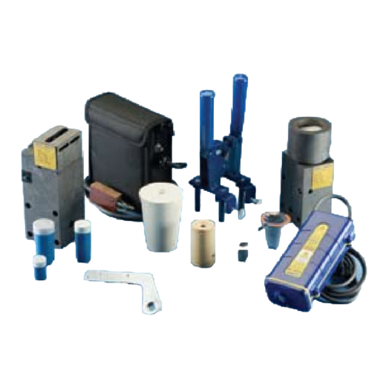
- Page 4 The CADWELD Process ® Fig. 1 Always wear protective safety glasses and gloves while working with CADWELD exothermic welding ® products. Fig. 2 Gather the proper materials and equipment for the type of connection you are making. The typical CADWELD system requires a graphite mold, handle clamp, welding material, natural bristle brush for mold cleaning, wire brush for cleaning/preparing conductors, flint igniter, and propane torch.
- Page 5 The CADWELD Process ® Fig. 4 Inspect the mold ID tag to ensure that it corresponds to the application, indicated by the: 1. mold part number 2. conductor size 3. welding material required 4. other materials required The mold must be correct for the conductor size and application.
- Page 6 The CADWELD Process ® Fig. 7 Tighten the clamp thumbscrews onto the mold. Fig. 8 Close the grips to tightly lock the mold. Check for an appropriate seal on the mold. Fig. 9 If the mold does not seal properly, make adjustments to tighten/loosen the handle clamp.
- Page 7 The CADWELD Process ® Fig. 10 Graphite absorbs moisture. Ignite the propane torch and dry out the inside of the mold thoroughly on both sides, heating the mold to approximately 250 degrees Fahrenheit (120 degrees Celsius). Fig. 11 The conductors should be clean and dry before the connection is made.
- Page 8 The CADWELD Process ® Fig. 13 Insert the conductors and position them for the connection. Fig. 14 Close the clamp tightly once the conductors are properly positioned. Fig. 15 Steel disk found inside the packaging box of welding material.
- Page 9 The CADWELD Process ® Fig. 16 Insert the steel disk (concave side up) into the mold. Hold the steel disk on the side of the mold and let it slide into place. Fig. 17 Ensure that the steel disk is properly seated. Fig.
- Page 10 The CADWELD Process ® Fig. 19 Remove the lid over the mold crucible. Fig. 20 Quickly pour the loose welding material powder into the mold. Fig. 21 The bottom of the tube contains compressed material (starting material). Tap the bottom of the tube a couple of times to loosen this material.
- Page 11 The CADWELD Process ® Fig. 22 Pour 1/4 to 1/3 of the starting material over the welding material in the mold crucible. Fig. 23 Close the lid and pour the remaining 3/4 to 2/3 of the starting material into the slot on the mold cover. NOTE: Welding material is an exothermic mixture and reacts to produce hot molten material with temperatures in excess of 2500 degrees Fahrenheit...
- Page 12 ® Fig. 27 CADWELD graphite molds will last approximately 50 connections. Use a soft cotton cloth or a soft bristle brush (ERICO part #T394) to clean inside the mold ® cavity and cover. Fig. 28 You are ready to make another CADWELD connection.
- Page 13 The CADWELD PLUS Process ® Fig. 1 Always wear protective safety glasses and gloves while working with CADWELD exothermic products. ® Fig. 2 Prepare the proper materials and equipment for the type of connection you are making. The CADWELD ® PLUS system requires a graphite mold, mold clamp, CADWELD PLUS welding material cup, natural bristle brush for mold cleaning, wire brush for cleaning/...
- Page 14 The CADWELD PLUS Process ® Fig. 4 Inspect the mold ID tag to ensure that it corresponds to the application, indicated by the: 1. mold part number 2. conductor size 3. welding material required 4. other materials required The mold must be correct for the conductor size and application.
- Page 15 The CADWELD PLUS Process ® Fig. 7 Tighten the clamp thumbscrews onto the mold. Fig. 8 Close the grips to tightly lock the mold. Check for an appropriate seal on the mold. Fig. 9 If the mold does not seal properly, make adjustments to tighten/loosen the handle clamp.
- Page 16 The CADWELD PLUS Process ® Fig. 10 Graphite absorbs moisture. Ignite the propane torch and dry out the inside of the mold thoroughly on both sides, heating the mold to approximately 250 degrees Fahrenheit (120 degrees Celsius). Fig. 11 The conductors should be clean and dry before the connection is made.
- Page 17 The CADWELD PLUS Process ® Fig. 13 Insert the conductors and position them for the connection. Fig. 14 Close the clamp tightly once the conductors are properly positioned. Fig. 15 Remove the proper CADWELD PLUS welding ® material cup from the plastic container. Inspect the cup to ensure it is tightly sealed and the ignition strip is securely attached to the seal.
- Page 18 The CADWELD PLUS Process ® Fig. 16 Place the cup into the top of the mold. Make sure the ignition strip nests into the recess on the top edge when the cover is closed. Fig. 17 Battery powered control unit. Fig.
- Page 19 The CADWELD PLUS Process ® Fig. 19 Close the graphite mold lid. Advise nearby personnel of welding operations in the area. Fig. 20 Using the control unit, press the button and hold, while you observe the “ready” indicator light. A green light will blink for a few seconds and then will change to a constant light.
- Page 20 ® Fig. 24 CADWELD graphite molds will last approximately 50 connections. Use a soft cotton cloth or a soft bristle brush (ERICO part #T394) to clean inside the mold ® cavity and cover. Fig. 25 You are ready to make another CADWELD connection.
- Page 21 The CADWELD EXOLON Process ® Fig. 1 Always wear protective safety glasses and gloves while working with CADWELD exothermic products. ® Fig. 2 Prepare the proper materials and equipment for the type of connection you are making. The CADWELD ® EXOLON system requires a CADWELD EXOLON graphite mold, handle clamp, welding material, wire brush for cleaning/preparing conductors, battery...
- Page 22 The CADWELD EXOLON Process ® Fig. 4 Inspect the mold ID tag to ensure that it corresponds to the application, indicated by the: 1. mold part number 2. conductor size 3. welding material required 4. other materials required The mold must be correct for the conductor size and application.
- Page 23 The CADWELD EXOLON Process ® Fig. 7 Tighten the clamp thumbscrews onto the mold. Fig. 8 Close the grips to tightly lock the mold. Check for an appropriate seal on the mold. Fig. 9 If the mold does not seal properly, make adjustments to the handle clamp.
- Page 24 The CADWELD EXOLON Process ® Fig. 11 The conductors should be clean and dry before the connection is made. Use a propane torch to dry wire conductors and remove remaining cleaning residue, solvent, or water before making the CADWELD ® connection.
- Page 25 The CADWELD EXOLON Process ® Fig. 14 Each CADWELD EXOLON package contains 2 filters ® for a low emission connection. Insert the white ceramic and black graphite filters into the mold cover. (Filters must be changed every 4 connections.) NOTE: If using XL200 welding material or higher, 3 filters (1 white, 2 black) are included in the weld metal package.
- Page 26 The CADWELD EXOLON Process ® Fig. 17 Steel disk found inside the packaging box of welding material. Fig. 18 Insert the steel disk (concave side up) into the mold. Hold the steel disk on the side of the mold and let it slide into place.
- Page 27 The CADWELD EXOLON Process ® Fig. 21 Quickly pour the loose welding material powder into the CADWELD EXOLON mold. NOTE: Welding material is an exothermic mixture and reacts to produce hot molten material with temperatures in excess of 2500 degrees Fahrenheit (1400 degrees Celsius) and a localized release of smoke.
- Page 28 The CADWELD EXOLON Process ® Fig. 24 CADWELD EXOLON battery pack. ® Fig. 25 Take the alligator clips and clip them onto the wire leads. Remove or protect fire hazards in close proximity to the connection. Advise nearby personnel of welding operations in the area. Fig.
- Page 29 CADWELD EXOLON graphite molds will last ® approximately 50 connections. Use a soft cotton cloth or a soft bristle brush (ERICO part #T394) to ® clean inside the mold cavity and cover; remove any slag left from the exothermic reaction.
- Page 30 The CADWELD ONE SHOT Process ® Fig. 1 Always wear protective safety glasses and gloves while working with CADWELD exothermic products. ® Fig. 2 Gather the proper materials and equipment for the type of connection you are making. The CADWELD ®...
- Page 31 The CADWELD ONE SHOT Process ® Fig. 4 The conductors should be clean and dry before the connection is made. Use a propane torch to dry wire conductors and remove remaining cleaning residue, solvent, or water before making the CADWELD ®...
- Page 32 The CADWELD ONE SHOT Process ® Fig. 7 Insert the conductors and position them for the connection. Fig. 8 Place the steel disk into the CADWELD ONE SHOT ® with the concave side facing up. Fig. 9 Ensure that the steel disk is properly seated inside the CADWELD ONE SHOT.
- Page 33 The CADWELD ONE SHOT Process ® Fig. 11 Quickly pour the loose welding material powder into the CADWELD ONE SHOT mold. ® Fig. 12 Place the cover on the top of the CADWELD ONE SHOT. Fig. 13 The bottom of the tube contains compressed material (starting material).
- Page 34 The CADWELD ONE SHOT Process ® Fig. 15 Aiming the flint igniter from the side, ignite the starting material on the mold cover. Withdraw the igniter quickly to prevent fouling. Allow approximately 30 seconds for completion of the reaction and solidification of the molten material. Fig.
- Page 35 The CADWELD PLUS ONE SHOT Process ® Fig. 1 Always wear protective safety glasses and gloves while working with CADWELD exothermic products. ® Fig. 2 Prepare the proper materials and equipment for the type of connection you are making. The CADWELD ®...
- Page 36 The CADWELD PLUS ONE SHOT Process ® Fig. 4 The conductors should be clean and dry before the connection is made. Use a propane torch to dry wire conductors and remove remaining cleaning residue, solvent, or water before making the CADWELD ®...
- Page 37 The CADWELD PLUS ONE SHOT Process ® Fig. 7 Insert the conductors and position them for the connection. Fig. 8 Inspect the cup to ensure it is tightly sealed and the ignition strip is securely attached to the seal. Fig. 9 Place the welding material cup into the top of the mold.
- Page 38 The CADWELD PLUS ONE SHOT Process ® Fig. 11 Battery powered control unit. Fig. 12 Place the ignition strip into the control unit connector. Remove or protect fire hazards in close proximity to the connection. Advise nearby personnel of welding operations in the area. Fig.
- Page 39 The CADWELD PLUS ONE SHOT Process ® Fig. 14 Remove and dispose of the used CADWELD PLUS ® weld metal cup. Fig. 15 Break the ceramic CADWELD ONE SHOT mold off ® of the connection. Avoid contact with hot materials. See the “Installers &...
- Page 40 Thailand Hong Kong United Arab Emirates Hungary United Kingdom Indonesia United States Italy Copyright ©2009 ERICO International Corporation. All rights reserved. CADDY, CADWELD, CRITEC, ERICO, ERIFLEX, ERITECH, and LENTON are registered trademarks of ERICO International Corporation. www.erico.com E834I E1123LT08WWEN 0071M9...
Need help?
Do you have a question about the Eritech Cadweld and is the answer not in the manual?
Questions and answers