Advertisement
Table of Contents
- 1 General Description
- 2 Quality Assurance
- 3 Ce Declaration of Conformity
- 4 Installation
- 5 Technical Data
- 6 Switches and Indicators
- 7 Start-Up Procedure
- 8 Shutdown Procedure
- 9 Cleaning Procedure
- 10 Airflow Measurements
- 11 Alarm Circuits
- 12 Electrical Protection
- 13 Fan Speed Control
- 14 Engineer S Menu
- 15 General Notes
- Download this manual
Advertisement
Table of Contents

Related Manuals for CAS BioMAT 1

Summary of Contents for CAS BioMAT 1
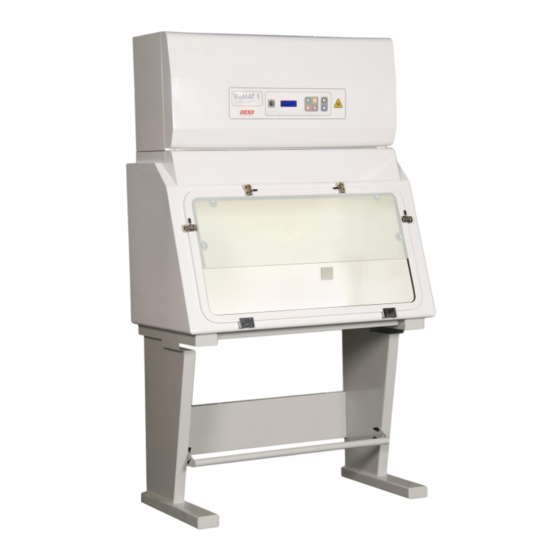
- Page 1 BioMAT ® Safety Cabinet...
- Page 2 Section Description Section 1 General Description Your Manual Quality Assurance/CE compatibility Cabinet Siting Installation Avoiding Disturbances Technical Data Your Manual Section 2 Switches & Indicators Start Up Procedure Shut Down Procedure Using your Cabinet Cleaning Procedure Fumigation & Formalin Quantities Fumigation Procedure Airflow Measurements Ultraviolet Radiation...
-
Page 3: General Description
General Description 1.1 Your BioMAT 1 Microbiological Safety Cabinet has been designed to provide optimum performance for operator protection. Using the latest in microprocessor and fan technology, it is designed to exceed the performance requirements of the European Microbiological Safety Cabinet Standard EN12469:2000. -
Page 4: Quality Assurance
Ø Extension, modification, relocation, repairs or other maintenance is carried out by CAS personnel or persons authorised by CAS or, in the case of electrical work, by qualified electricians. Ø In the case of repair or maintenance, replacement parts supplied by CAS must be used. - Page 5 Cabinet Siting 1.3 The siting of your Safety Cabinet is extremely important. Air currents and the movement of people in the laboratory can adversely affect the performance. Safety Cabinets should be sited away from; Ø Doors and windows which open Ø...
-
Page 6: Installation
KI Discus Test (operator protection test) to assess the containment of the cabinet. CAS employs a team of fully trained installation and commission engineers to carry out all work necessary. This ensures that all new safety cabinets operate to the desired performance. - Page 7 Avoiding Disturbances 1.5 The sketches below show recommendations for avoiding disturbances for both cabinet operator and safety cabinet performance. 1500 1000 Keep pedestrians away from the front Keep clear of adjacent wall Position well away from the door openings of your safety cabinet 2000 1500 Position clear of bench opposite...
-
Page 8: Technical Data
Technical Data 1.6 Cabinet Size 900mm 1200mm 1500mm 1800mm Dimensions External Dimensions (w/d/h) 900/630/1250 1200/630/1250 1500/630/1350 1800/630/1350 Internal Dimensions (w/d/h) 895/625/700 1195/625/700 1495/625/700 1795/625/700 Opening to Work Area (w/h) 710/200 1010/200 1310/200 1610/200 Weight Typical Loading Capacity Work Surface Air Volumes Typical Exhaust Air Volume m³/sec 0.120... -
Page 9: Switches And Indicators
Your Manual 1.7 This user manual has been prepared to provide a basic operating and maintenance instruction. It is intended to supplement existing in-house procedures and codes of practice, and not to replace them. If further advice is required on the use or maintenance of this equipment, the staff of Contained Air Solutions Ltd. - Page 10 The diagram below shows a typical control panel membrane layout for the BioMAT 1 Safety Cabinet. B io M A T 1 AIRFLOW SA FE BioMA T 1 C L A S S 1 M I C R O B I O L O G I C A L S A F E T Y C A B I N E T...
-
Page 11: Start-Up Procedure
Start Up Procedure 2.2 The following notes are for guidance where local laboratory instructions do not exist or are inappropriate. They should complement, not replace, existing codes of practice issued by your Laboratory Safety Officers. Ø Ensure power supply to the cabinet is switched on, as evidenced by the main display being illuminated. -
Page 12: Shutdown Procedure
Shut Down Procedure 2.3 Ø The work area should be cleared of any apparatus / equipment and cleaned in accordance with laboratory codes of practice. The cabinet should be left running for a few minutes to clear any residual aerosols. Ø... -
Page 13: Cleaning Procedure
Cleaning Procedure 2.4 Regular cleaning is very important to prevent the build-up of dirt and hence potentially infectious material. Routine swabbing of work surfaces with 70% v/v IMS (ethanol) or IPA (Isopropyl Alcohol) is recommended. For cleaning the work surfaces, swabbing with a mild detergent in warm water is very effective. - Page 14 A convenient way of generating sufficient formaldehyde is to boil off Formalin (40% formaldehyde BP or equivalent) in a suitable vessel such as a formalin vaporiser. These are available from CAS. Always consult your Laboratory Safety Officer prior to fumigation of a safety cabinet.
- Page 15 Fumigation Procedure 2.6 Ø Switch off the cabinet fans by pressing the green button A on the control panel. Ø For re-circulating type safety cabinets the fumigation extract kit (optional) should be fitted to the cabinet discharge and ensure that the manual damper is fully closed. For cabinets connected to a duct system proceed as follows: §...
- Page 16 For re-circulating type safety cabinets press the fumigate button to complete cycle and open the manual shut-off damper on the fumigation adaptor kit (Optional) having first fitted the extract tubing and placed the discharge point in a location approved by the Laboratory Safety Officer.
-
Page 17: Airflow Measurements
KI test. Anemometer positions for the 1200, 1500 & 1800mm size of cabinets are illustrated below. The results should be recorded to monitor cabinet performance over time. 1200mm BioMAT 1 1500 & 1800mm BioMAT 1... - Page 18 Ultraviolet Radiation (Optional) 2.8 Ultraviolet Radiation (UV) lamps may be fitted as an optional extra; these can be fitted as new in our factory or retrofitted at a later date on site. If installed the cabinet will have1 or 2 (Depending on cabinet size) short wavelength Ultraviolet (UV) tubes emitting 254 nano metres fitted to the inside work area of the safety cabinet.
- Page 19 Typical display during normal operation shown below: AIRFLOW SAFE BioMAT 1 In the event of an alarm condition the display will clearly indicate the fault; this will remain displayed until fault is rectified.
-
Page 20: Alarm Circuits
Alarm Circuits 3.2 There are three standard alarm circuits on the BioMAT 1 Re-circulating and Exhaust type Safety Cabinets. INFLOW LOW ALARM Sensed by an accurate pressure sensor mounted on the main printed circuit board and connected via tubing to the sensing points within the cabinet body, this will sense low airflow caused by fan failure or filter soiling, and transmit the signal to the display meter on the front panel and alarm circuit. -
Page 21: Electrical Protection
Electrical Protection 3.3 Ensure the Safety Cabinet is isolated from the mains supply prior to opening access panels. Warning Fuses There are 11 fuses mounted on the printed circuit board to protect the electrical circuits of the cabinet. The cabinet controls are housed behind the front control panel which is secured with two screws located across the bottom edge. -
Page 22: Fan Speed Control
Engineer s Menu. It is important any changes to fan speeds must be made by a CAS service engineer or alternative competent service provider, failure to do this may result in the warranty being invalid. -
Page 23: Engineer S Menu
Engineer s Menu 3.5 It is important any changes within the Engineer s Menu be conducted by a CAS service engineer or alternative competent service provider; failure to do so may result in the warranty being invalid. Warning The buttons located on the front control membrane have a second function once access to the Engineer s Menu has been gained. - Page 24 Engineer s Menu Sequence LOW ALARM 40 Pa HIGH ALARM 80 Pa INFLOW FAN 65 % U.V. LIGHTING 060 MINUTES TIME ADJUST 14:54 EXHAUST SENSOR 20 Pa SERVICE TIMER RESET INITIALISE VALUE INITIALISE (0)
- Page 25 Re-circ HEPA Filter (Air returned to room) 4.2 Two HEPA filters are located on the top of the main body of the cabinet separated by a spacer section and held in place by four M8 filter bolts. IMPORTANT Cabinet must be decontaminated prior to changing any HEPA filters, see section 2.6 Only replace or examine filters if authorised to do so by the Safety Officer or the person in charge of the laboratory.
- Page 26 Exhaust HEPA Filter (Air ducted to atmosphere) 4.3 The HEPA filter is located on the top of the main body of the cabinet held in place by four M8 filter bolts. IMPORTANT Cabinet must be decontaminated prior to changing any HEPA filters, see section 2.6 Only replace or examine filters if authorised to do so by the Safety Officer or the person in charge of the laboratory.
-
Page 27: General Notes
General Notes 4.4 Ø Do not store equipment inside the Microbiological Safety Cabinet. The amount of equipment should be kept to a minimum to reduce the disruption to the airflow patterns within the cabinet. Ø A Bunsen burner should not be used inside the cabinet. Ø... - Page 28 SERVICE SCHEDULE 6.1 Class II Microbiological Safety Cabinets Schedule of work included in service agreement Filter Integrity Test (D.O.P) on all main filter(s) and seals Airflow Profiling ensuring compliance to latest British & European Standards Operator Protection Testing (K.I. Discus) 1 x Per Annum Check and adjust alarm parameters &...
- Page 29 Spares List 6.2 Shown below are ordering codes for the most common parts used on the BioMAT 1 Safety Cabinets. In addition to these items we stock a vast range of Spares, consumables and optional extras. If you cannot see what you require please give us a call on the telephone number shown below.
Need help?
Do you have a question about the BioMAT 1 and is the answer not in the manual?
Questions and answers