Table of Contents
Advertisement
Advertisement
Table of Contents

Summary of Contents for Gopel Electronic SFX-TAP2/C
- Page 1 Desktop Transceiver SFX-TAP4/C SFX-TAP2/C Technical Description Version 0.1 GÖPEL electronic GmbH Göschwitzer Str. 58/60 D-07745 Jena Tel.: +49-3641-6896-0 Fax: +49-3641-6896-44 E-Mail: support@goepel.com ® Intelligent Boundary Scan Solutions http://www.goepel.com...
- Page 2 © 2005 GOEPEL electronic GmbH. All rights reserved. The software described in this manual as well as the manual itself are supplied under license and may be used or copied only in accordance with the terms of the license. The customer may make one copy of the software for safety purposes. The content of the manual is subject to change without notice and is supplied for information only.
-
Page 3: Table Of Contents
ESD / Latch up Strength ..................7 Current Input ......................7 Device Structure......................7 Interfaces ........................ 7 Structure of the Desktop Transceivers SFX-TAP4/C (SFX-TAP2/C) ..... 7 AUX Connector ....................... 8 PwrCtrl Connector ....................8 TAP/PIP Connector ....................8 Hardware Components ....................9 Voltage Supply...................... -
Page 5: Definition
1 Definition The Desktop Transceiver SFX-TAP4/C (SFX-TAP2/C) is a Hardware product of the company GÖPEL electronic GmbH and belongs to the product group Boundary Scan test tools. It can only be operated together with the „SYSTEM CASCON“ and „POLARIS“ [1] software or a respective dynamic link library (DLL) of version 4.2.1 or higher from GÖPEL electronic. -
Page 6: Scope Of Delivery
2 Technical Data 2.1 General Information The Desktop Transceiver SFX-TAP4/C (SFX-TAP2/C) forms together with the Host Controller a Boundary Test System that allows versatile kind of connections the Unit-Under-Test (UUTs). The following device properties allow maximum flexibility of the interface to the UUT: voltage-programmable Testbus interface in the range of 1.8V-4.5V, inputs (TDI... -
Page 7: Esd / Latch Up Strength
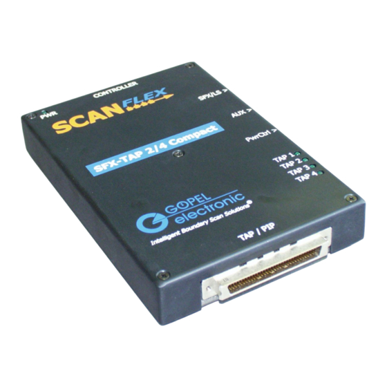
: TAP/PIP connector (68-pole, SCSI) 2 analog I/O : AUX connector PowerCtrl OUT : PwrCtrl connector 3.2 Structure of the Desktop Transceivers SFX-TAP4/C (SFX-TAP2/C) Figure 1: Assignment of the Connector and LED of the Desktop Transceiver SFX-TAP4/C (SFX-TAP2/C) Desktop Transceiver SFX-TAP4_2/C, V0.1, Technical Description... -
Page 8: Aux Connector
3.3 AUX Connector Figure 2: AUX connector on the side panel of the Compact Transceiver Assignment of the AUX connector: TRG0 TRG1 TRG2 D-AUX1 D-AUX2 D-AUX3 A-AUX1 A-AUX2 2, 4, 6, 8, 10, 12, 14, 16 3.4 PwrCtrl Connector Figure 3: PwrCtrl connector on the Side panel of the Compact Transceiver Assignment of the PwrCtrl connector: PWR1 PWR2... -
Page 9: Hardware Components
4 Hardware Components 4.1 Voltage Supply Die voltage supply of the Desktop Transceiver SFX-TAP4/C (SFX-TAP2/C) is obtained by using the wall power supply. Connect it to the PWR plug of the Transceiver. 4.2 PIP Complex Count of I/O: Formatting: 4 x 8, 2 x 16 Input voltage range: 0 V –... -
Page 10: Trigger Signals
The output current must not exceed 25 mA. Input signals < 1.0 V will be seen as LOW, > 2.4 V as HIGH. Refer to PCA9555 [3] for further details to signal properties of these digital IO signals. 4.5 Trigger Signals The signals on the pins 1, 3, and 5 of the AUX connector are trigger signals. -
Page 11: Output Voltages
4.6 Output Voltages 4.6.1 Output Voltages on TAP/PIP Connector: On TAP/PIP-Connector, two voltages are provided: +5.0V (pin 68) and +3.3V (pin 1). Both are equipped with self-restoring fuses. This means the voltages are available again after solving the reason of a possible overcurrent. The nominal value for the fuses is 500 mA. The pins 1 and 68 of the TAP/PIP connector are not protected against wrong polarization! The current consumption must not exceed 100 mA. -
Page 12: Boundary Scan Interface
It is recommended to design the Testbus signals as twisted pair with GND. Note: Connect the TDI line(s) of the Desktop Transceiver SFX-TAP4/C (SFX-TAP2/C) with TDO lines of the UUT(s). Connect TDO line(s) of the SFX-TAP4/C (SFX-TAP2/C) with the TDI input(s) of the UUT. -
Page 13: Recommended Operating Conditions
4.8.2 Recommended Operating Conditions Supply Voltage I/O Pads (V Pads) +1.8V to +5.0V DC Input Voltage I/O Pads (V Pads) -0.2V to +5.0V Output Voltage I/O Pads (V Pads) Outputs 3-Stated 0V to +5.0V Outputs Active 0V to V +0.5V Output Current in I Vcc=5.0V ±24mA... - Page 14 Electrical Characteristics (2.7 V < V ≤ ≤ ≤ ≤ 3.6 V) for I/O Pins Symbol Conditions Vcc [V] Min. Max. Unit 2.7 to 3.6 2.7 to 3.6 =-100µA 2.7 to 3.6 Vcc-0.2 =-12mA =-18mA =-24mA =100µA 2.7 to 3.6 =12mA =18mA =24mA...
-
Page 15: Input Stage
Input Stage The input stage consists of a High-Speed comparator. Following operating conditions are recommended: 5.0 V Programmable Threshold 0.0 to 3.0 V Max. Input Voltage Range -0.3 V to 5.5 V 5 Software Settings of the Testbus Interface 5.1 TCK Frequency The effective test speed is defined by software access time and frequency of TCK. - Page 16 Valid parameters (black) are accepted here even in cases outside the controller specific range as they are depending on the setting of the UUT. All settings in this index card don’t have any impact to SCANFLEX products. Voltages and delay values are defined in a further entry field. Figure 7: TCK Setting Desktop Transceiver SFX-TAP4_2/C, V0.1, Technical Description...
-
Page 17: Tap Specific Settings
5.2 TAP Specific Settings The system SCANFLEX supports up to 8 independent TAPs. The SFX-TAP2(4)/C supports two or four TAPs respectively. Each TAP can be configured in its properties individually. These are the TAP specific settings: Aktivierung der TAPs • Testbus output and Input voltages •... - Page 18 Figure 8: Define a new Configuration Now select the just defined configuration. On the right side, select SFX Contoller in the group Modul types. Press button Insert. Figure 9: Insert Controller Select SFX_controller in the left panel. Press the button Auto detect on the right. Desktop Transceiver SFX-TAP4_2/C, V0.1, Technical Description...
- Page 19 Figure 10: Auto Detection The result of successful detection is shown in the right panel. The recognized SCANFLEX hardware is inserted under SFX-HS (SFX-LS1 and SFX-LS2). In our example, a SFX-TAp4 has been recognized which appears as SFX_TAP_splitter_4_1 in the left panel. Again, select the recognized hardware and after pressing the Enable button it is activated for the current UUT.
- Page 20 As a result of successful enable, you can see in the right panel a further register named Project Parameters. There, all current parameters are displayed. They can be modified there by Edit. Figure 12: Overview of project parameters The TAP settings can be changed by selecting the register TAP. The next figure shows the TAP specific parameters.
-
Page 21: Tic Type
Since in the example one SFX-TAP4 is connected with the SCANFLEX controller, four sub registers appear in the register TAP, one per TAP. This allows TAP related definition of the values. Moving the mouse cursor to an entry area and waiting 1 sec, the allowed value range is displayed. -
Page 22: Inline Resistor
5.2.4 Inline Resistor The Inline resistors are applied to all TAP outputs (TCK, TMS, TDO and /TRST) with the same value. Following values can be selected (see figure 13): Tristate --> the driver stays in tristate mode during test execution •... - Page 23 delay delay TDO mit ∆t - ∆t + ∆t - ∆t + ∆t = 1 / T Figure 14: Timing diagram for UUT TCK-TDO delay The delay time Delay (t ) to be entered is the elapsing time between falling TCK edge on the delay TAP/PIP connector of the SFX-TAP4 (SFX-TAP2) until arriving the UUT’s TDO response on the same connector.
- Page 24 Example: Target frequency: 30 MHz Tolerance: 8 ns Software setting: 25 MHz (1 / (4 x (8 ns + 2 ns)) = 25 MHz) The typical time delay value fort he cable is about 5 ns / m. Multiply this by to because of the to and from signal propagation.
-
Page 25: Testbus Signals On Tap/Pip User Interface
All Testbus signals are provided on the connector TAP/PIP (SCSI68) (see TAP/PIP User interface). 5.2.9 SCP Controller The Desktop Transceiver SFX-TAP2/C allows the control of „SCP Modules“. These modules typically provide additional BScan test resources in order to increase the test coverage of a board. Typical application is testing through edge connectors. -
Page 26: Appendix
6 Appendix 6.1 TAP/PIP : User Interface SFX-TAP4/C + 5.0V PIP 4.7 PIP 4.6 PIP 4.5 PIP 4.4 PIP 4.3 PIP 4.2 PIP 4.1 PIP 4.0 PIP 3.7 PIP 3.6 PIP 3.5 PIP 3.4 PIP 3.3 PIP 3.2 PIP 3.1 PIP 3.0 PIP 2.7 PIP 2.6... -
Page 27: Tap/Pip : User Interface Sfx-Tap2/C
PIP 1.1 PIP 1.0 D-AUX3 TRG0 TRG1 SCP-TDI SCP-TCK SCP-TDO SCP-TMS D-AUX2 TDI2 D-AUX1 TDO2 TCK2 TMS2 TDI1 TDO1 TCK1 TMS1 /TRST + 3.3V Figure 17: Pin assignment User Interface TAP/PIP connector for SFX-TAP2/C Desktop Transceiver SFX-TAP4_2/C, V0.1, Technical Description... -
Page 28: Order Information
7 Order Information Desktop Transceiver SFX-TAP4/C STT-010 Desktop Transceiver SFX-TAP2/C STT-011 8 References [1] - User Manual „SYSTEM CASCON“, GÖPEL electronic GmbH - 2005 [2] - CION: Configurable I/O Network, V1.4, Data Sheet GOEPEL electronic GmbH 2002 [3]..- PCA9555 Product data sheet, Supersedes the data of 2004 Jul 27, Philips Semiconductors, 2004 Sep 30 Desktop Transceiver SFX-TAP4_2/C, V0.1, Technical Description...
Need help?
Do you have a question about the SFX-TAP2/C and is the answer not in the manual?
Questions and answers