
Summary of Contents for Polysoude MU IV Series
- Page 1 MU IV TIG – with or without filler wire , AVC , OSC Open Welding Head User manual PN-0706056 THE ART OF WELDING...
- Page 2 MU IV Review of document Ind. 2 Revision of document Ind. 3 Update of the graphics standards and equipment compatibility Ind. 4 Update: Tools box and MU IV wiring plug: AVC/OSC wiring Ind. 5 Update: Sparepart box Ind. 6 Update Ind.
-
Page 3: Table Of Contents
MU IV Contents Safety precautions .................... 5 1. 1. Arc welding hazards ................... 5 1. 2. Meaning of the symbols ..................5 1. 3. Recommendations ..................... 6 General information ..................9 2. 1. Reference documents ..................9 2. 2. Applicable directives ..................9 General introduction ..................11 3. - Page 4 MU IV 4-80 PN-0706056 Ind. 8 THE ART OF WELDING...
-
Page 5: Safety Precautions
MU IV Safety precautions Note: Protect yourself and others from injury - read and follow these instructions 1. 1. Arc welding hazards The following symbols are used in the text to draw your attention and to identify risks and dangers. When you see a symbol, consult the safety instructions in the Recommendations chapter hereafter. -
Page 6: Recommendations
MU IV 1. 3. Recommendations Risk of fume or gas inhala- tion Risk of electric shocks During welding, fumes and gases are released which are harmful to your health. Avoid inhaling fumes. Live parts include the electrode, the weld circuit, Sources of fume and gas emissions: basic materi- the supply circuit and the internal circuits, the al, filler metal, coating (flux) by covered electrode,... - Page 7 MU IV Warning: hot parts – Risk of Risk of explosion burns Do not touch welded or torch-cut parts. When These risks related to the use and handling of gas handling hot workpieces, use suitable tools and/ cylinders and flying sparks. or wear thick, heat-proof welding gloves to avoid burns.
- Page 8 MU IV 8-80 PN-0706056 Ind. 8 THE ART OF WELDING...
-
Page 9: General Information
MU IV General information 2. 1. Reference documents PN-0706043 Illustrated parts lists of the wire feeder PN-0706044 User guide of the wire feeder PN-0706046 Illustrated parts lists MU IV 28 welding head PN-0706047 Illustrated parts lists MU IV 38 welding head PN-0706048 Illustrated parts lists MU IV 64 welding head PN-0706049... - Page 10 MU IV 10-80 PN-0706056 Ind. 8 THE ART OF WELDING...
-
Page 11: General Introduction
The MU IV welding head range is used to weld tubes with an exterior diameter of between Ø8 mm and Ø275 mm. It includes 10 head sizes with different welding capacities as shown in the following table and diagram: These instructions do not deal with elements that are not supplied by Polysoude. 3. 2. -
Page 12: Environment And Operating Conditions
MU IV 3. 3. Environment and operating conditions This material is designed to function in the workshop in non-explosive atmospheres. In the operational phase, the following conditions must be respected: The ambient air temperature is between -10° and +40°C. Relative humidity: •... -
Page 13: Fig.3.1 - Possible Combinations
MU IV Fig.3.1 - Possible combinations PN-0706056 Ind. 8 13-80 THE ART OF WELDING... -
Page 14: Fig.3.2 - Illustration Of The Subassemblies Of The Mu Iv
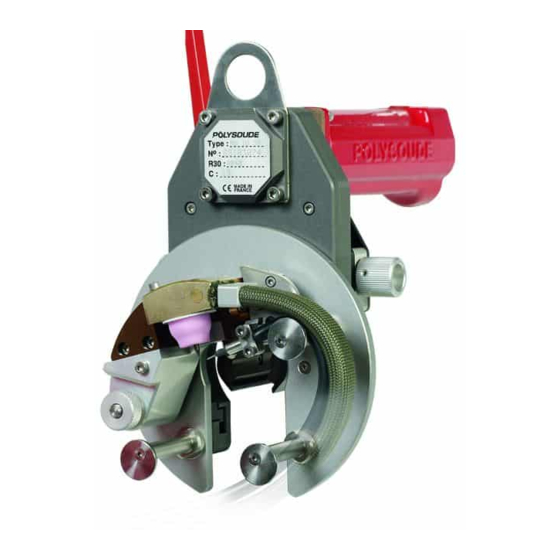
MU IV 3. 4. 1. MU IV weld head Illustration of the subassemblies of the MU IV. • Motor (Fig.3.2 - 1). • Coupling between the motor and the drive, called the “motor output” (Fig.3.2 - 2). • Drive mechanism (Fig.3.2 - 3). •... - Page 15 MU IV PN-0706056 Ind. 8 15-80 THE ART OF WELDING...
-
Page 16: Fig.3.3 - Motors
The ratio of the reducer is R=1/400. An encoder (Fig.3.3 - 2) attached to the motor in- forms the Polysoude welding generator of the actual position of the torch and is used to control the weld- ing sequence (control of the sector starts and stops). -
Page 17: Fig.3.4 - Couplings
MU IV Couplings: A number of motor outputs are available. They are used to couple the motor to the drive. A clutch is installed on large heads (MU IV 195 to 245) to facilitate the repositioning of the head after a weld cycle. This includes: •... -
Page 18: Fig.3.5 - Clamps
MU IV Clamping devices: Two systems are available: The chuck clamp: The chuck clamp is made up of two synchronized arms (Fig.3.5 - 2), whose profile can be manually adjusted to clamp and centre the assembly on the part to be welded. A single control lever (Fig.3.5 - 1) is used to clamp and unclamp. -
Page 19: Fig.3.6 - Plates
MU IV Welding plates: Two systems are available: Simple plate (Fig.3.6 - 1-2): The simple plate is used to hold and adjust the torch with regard to the welding plane. The simple plate is manually adjusted. This plate is made up of: •... -
Page 20: Fig.3.8 - Gas Lenses
The torch is attached to the plate’s torch support. It is liquid cooled. It is connected to the generator by: • A flexible multi-duct (Polysoude patent) for power, gas and coolant supply. • A 7-meter harness fitted with quick-fit connections. -
Page 21: Technical Characteristics
MU IV 3. 5. Technical characteristics Dimensions (ready to weld, integrated feeder included) Dimensions See Dimensions chapter Duty cycles Max. peak I (A) Max. average I (A) Wireless MU IV 250 to 100% 190 to 100% MU IV with wire filler (Amps) 250 to 100% 190 to 100% MU IV AVC/OSC (Amps) -
Page 22: Equipment Compatibility
MU IV 3. 7. Equipment compatibility The MU IV welding heads are compatible with all the generators in the Polysoude range, provided that the duty cycles (heads and generators) and options thereof are respected (AVC/OSC) 22-80 PN-0706056 Ind. 8 THE ART OF WELDING... -
Page 23: Dimensions
MU IV 3. 8. Dimensions MU IV Double clamp Ø A Min.Ø/Max.Ø recommended MU IV 14/28 P * MU IV 8/38 P MU IV 19/64 P * MU IV 19/80 P MU IV 19/104 P * 121.5 MU IV 25/115 P MU IV 25/128 P * MU IV 76/195 P 30.5... - Page 24 MU IV Amplitude MU IV AVC/BL Double clamp Ø A Min.Ø/Max.Ø recommended MU IV 8/38 P MU IV 19/64 P * MU IV 19/80 P MU IV 19/104 P * 121.5 MU IV 25/115 P MU IV 25/128 P * MU IV 76/195 P MU IV 101/245 P * MU IV 114/275 P...
- Page 25 MU IV C / Cb Ø A > A/2 PN-0706056 Ind. 8 25-80 THE ART OF WELDING...
-
Page 26: Installation
MU IV Installation 4. 1. Handling All installation and maintenance operations must be performed with the equipment switched off. To handle the unit always use the positions provided to this ef- fect. Never use the machine parts as handles: Risk of damaging or destroying the equipment. -
Page 27: Bundle
MU IV Fig.4.1 - Slinging 4. 4. Bundle The user is responsible for installing and using the arc welding equipment in accordance with the manufacturer's instructions. If electromagnetic interference is detected, the user of the arc weld- ing material is responsible for correcting the situation with the manufacturer's assistance (extract from the standard EN 60974- 10 2003 –... -
Page 28: Use
MU IV 5. 1. Precautions This machine should only be used by suitably qualified staff in ac- cordance with the rules stipulated by labour legislation. Any operation involving contact with the AVC axis or self-aligning with the oscillation axis must always be performed under the user's supervision (unless otherwise stated). -
Page 29: The Electrode
Avoid all contact between the filler metal and the electrode in order to avoid rapid wear of the elec- trode. The electrode provided by Polysoude is made of tungsten alloyed with additive element such as lanthanum. The outcome is an easier ignition and greater arc stability. -
Page 30: Fig.5.2 - "Gm Type" Gas Lens
MU IV 5. 2. 3. Selecting the gas lens MU IV Model Gas lens Length of the nozzles Min. Ø Maxi Ø Fig.5.2 - "GM Type" gas lens Fig.5.3 - "N Type" MU IV AVC/BL gas lens Model Gas lens Length of the nozzles Min. -
Page 31: Fig.5.5 - Gas Lens Assembly
MU IV 5. 2. 4. Assembly of the gas lens • Pass the electrode (Fig. 5.5 - 4) in the chuck (Fig. 5.5 - 1) with the tip of the electrode on the side of the slits in the chuck. •... -
Page 32: Fig.5.6 - Adjustment Of The Distance Between The Electrode And The Part
MU IV 5. 2. 7. Adjusting the distance between the electrode and the part MU IV 28, 38, 64, 80, 104, 115 and 128 welding heads without servo-control. The radial adjustment is made using the sen- sor screw (Fig.5.6 - 1) fitted with a countersunk hexhead. -
Page 33: Wire Sheaths
MU IV 5. 2. 8. Torch direction All the MU IV welding heads can direct the 45° torch from 0° to +45° (where 0° is the axis of the electrode perpendicular to the axis of the tube). Fig.5.8 - Torch direction 5. -
Page 34: Fig.5.9 - Wire Sheaths And Small Nozzles
MU IV For large tube diameters, and depending on the stiffness of the wire, it is possible to install a nozzle extension (Fig.5.9 - 3) between the nozzle and the sheath in order to limit the free length of wire between the bath and the nozzle outlet. -
Page 35: Ignition Ring
MU IV 5. 3. 3. Adjusting the electrode wire The position of the wire can be precisely adjusted in relation to the welding electrode. The average values for correct settings are: • Free length at outlet: Sf = 8 to 10 mm. •... -
Page 36: Built-In Feeder
MU IV 5. 5. Built-in feeder 5. 5. 1. Setting up the wire in the feeder • Unscrew the screw M3 and remove the cover (Fig. 5.12-View A). • Unscrew the adjustment screw for the gearing in order to move the feeder roller (12), away from the driving roller (1) (Fig. -
Page 37: Fig.5.12 - Placing The Wire
MU IV Fig.5.12 - Placing the wire PN-0706056 Ind. 8 37-80 THE ART OF WELDING... -
Page 38: Fig.5.13 - Wire Curve
MU IV 5. 5. 2. Adjustment of the wire curvature • Feed a few centimetres of wire, then check the curve (Fig.5.13 - View A). If the wire unwinds on the side opposite to the two straightening rollers (Fig.5.13 - View B): •... -
Page 39: Adjusting The Clamps
MU IV 5. 6. Adjusting the clamps 5. 6. 1. Chuck clamps • Place the welding head on the tube. • Close the clamp using the control lever (direction A) (Fig.5.14 - 1). In this position, the tube must be free. •... -
Page 40: Fig.5.15 - Shell Clamps
MU IV 5. 6. 2. Shell clamps • Install the shell corresponding to the diameter of the tube in the clamp (Fig.5.15 - 1). • Place the welding head on the tube. • Close the clamp using the control lever (direction A) (Fig.5.15 - 2). •... -
Page 41: Adjusting The Gas Flow Rate
MU IV 5. 7. Adjusting the gas flow rate The gas flow rate must be approximately: • 7 l/min for type P gas lenses • 8 l/min for type N gas lenses • 12 l/min for type GM gas lenses The gas flow rate must be adjusted to provide optimal protection, depending on the applications. -
Page 42: Maintenance And Troubleshooting
MU IV Maintenance and troubleshooting You must refer to the chapter on spare parts to obtain the part reference: Spare parts 6. 1. Troubleshooting - diagnostics assistance Function Kind of incident Possible causes No earth connection Braid cut No welding gas Welding current No igniting No ignition ring... -
Page 43: Routine Maintenance
MU IV 6. 2. Routine maintenance 6. 2. 1. Preventive maintenance Inspection of flexible pipes Frequency Operation - Every 3 Equipment switched off, power switch locked. months. Inspection of flexible pipes • Clean the flexible pipes with a paintbrush or cloth. •... - Page 44 MU IV Looking for leaks in the circuit Frequency Operation - Every 3 Live equipment, working. months. Reminder: Appearance of a leak • Noises. • Discharges. • Seepage. • Puddles. • Other abnormal and frequent elements. Every 3 Equipment switched off, power switch locked. months.
- Page 45 MU IV Checking the position switches Frequency Operation - Every 3 Equipment switched off, power switch locked. months. • Check the general condition of the position switch (body and head); check the fastening of the assembly. • Check the condition of the cable clamp (broken, unscrewed) and check its effect on the multicore cable manually.
- Page 46 MU IV Checking and lubricating the slides Consumables Frequency Operation - and tools Every 3 Equipment switched off, power switch locked. months. Protective casing • Check that the casings are not distorted, worn and unhooked. Every 3 Equipment switched off, power switch locked. months.
-
Page 47: Recommended Lubricant Brands
MU IV 6. 3. Recommended lubricant brands For the O For all motor-driven For mechanical For electrical contacts rings movements contacts KF:2301 silicon grease Molykote BR2 Plus Molykote BR2 Plus E452 gel 6. 4. Accessories box The wear and tear parts of the feeder and the torch, which are used to guide and convey the solder wire, must be suited to the type and the diameter of the solder wire. - Page 48 MU IV 6. 4. 2. Tools MU IV 28 MU IV 104 Order code Designation MU IV 80 MU IV 275 100003625 BTR wrench assembly Ref 82H 62209801 Box tools 240x195x42 62811004 Screwdriver 4x75 29810144 Pipe Wrench 48-80 PN-0706056 Ind. 8 THE ART OF WELDING...
-
Page 49: Repairs And Maintenance
6. 5. Repairs and maintenance The After Sales Service of Polysoude is at your service to provide information on any problems encoun- tered in using this product and to supply the spare parts you order. When ordering a spare part, do not forget to indicate the order code, as indicated in the spare parts section of your material instructions, as well as the serial number of your machine. - Page 50 MU IV 6. 5. 5. Cleaning and maintenance of the drive assembly Safety precautions Tools • Clean cloth. • Hex head key set Consumables - Spare parts Frequency - Replacement criteria • In the event of ingress of foreign bodies. Preconditions •...
- Page 51 MU IV PN-0706056 Ind. 8 51-80 THE ART OF WELDING...
- Page 52 MU IV 6. 5. 6. Replace the drive pin. Safety precautions Tools • Clean cloth. • Hex head key set • Pin punch Consumables - Spare parts • 2x14 elastic pin - Order code 1202006 Frequency - Replacement criteria • If the pin breaks.
- Page 53 MU IV PN-0706056 Ind. 8 53-80 THE ART OF WELDING...
- Page 54 MU IV 6. 5. 7. Replacing the optical sensor Safety precautions Tools • Clean cloth. • Hex head key set Consumables - Spare parts • Optical sensor: n° according to welding head Frequency - Replacement criteria • In case of wear or deterioration of the part. Preconditions •...
- Page 55 MU IV PN-0706056 Ind. 8 55-80 THE ART OF WELDING...
- Page 56 MU IV 6. 5. 8. Changing the wheel for wire, the wire feeder pressure rollers and the straightening roller. Safety precautions Tools • Clean cloth. • Flat screwdriver. • 2.5 Hex head key. Consumables - Spare parts • Ø 0.8 wire button - Order code: 11000107 (11) •...
- Page 57 MU IV PN-0706056 Ind. 8 57-80 THE ART OF WELDING...
- Page 58 MU IV 6. 5. 9. Replacing the inner wire sheath Safety precautions Tools • Clean cloth. • 2.5 Hex head key Consumables - Spare parts • Ø1.1x Ø2.4 Teflon liner sheath for Ø0.6 and Ø0.8 wires - Order code: 00552081 •...
- Page 59 MU IV PN-0706056 Ind. 8 59-80 THE ART OF WELDING...
- Page 60 MU IV 6. 5. 10. Repairing a leak in the multi-duct Safety precautions Tools • Clean cloth. • Cutter. • 2.5 Hex head key. Frequency - Replacement criteria • In the event of a leak Preconditions • Disconnect the equipment from the power supply. Procedure Removal •...
- Page 61 MU IV PN-0706056 Ind. 8 61-80 THE ART OF WELDING...
- Page 62 MU IV 6. 5. 11. Repairing broken brain in the multi-duct Note: This point only applies to breakages at the torch outlet (< 200 mm) and depends on the length of multi-duct required for the machine to work properly. Safety precautions Tools •...
- Page 63 MU IV PN-0706056 Ind. 8 63-80 THE ART OF WELDING...
- Page 64 MU IV 6. 5. 12. MU IV wiring plug: AVC/OSC wiring Safety precautions Tools • Clean cloth. • Set of BTR wrenches. • Crimping and cutting pliers • Soldering tool for electrical equipment Consumables - Spare parts • Silicone tube •...
- Page 65 MU IV • Connect the 12 core cable (4), which is already wired, to plug 00563302 (5). • Secure to the plate with a hex socket head screw (6). • Solder the induction coil to the nut (14) Do not overheat the induc- tion coil during the soldering operation.
- Page 66 MU IV Procedure (continued) • Insert a wire approximately 10 cm long into a sili- cone tube and crimp two Ø3 lugs. • Attach one of the lugs to the retaining screw of the induction coil (14). • Leave the other lug (15) free, ready to be connec- ted to the harness.
- Page 67 MU IV PN-0706056 Ind. 8 67-80 THE ART OF WELDING...
- Page 68 MU IV 6. 5. 13. MU IV wiring plug: cooled motor wiring Safety precautions Tools • Clean cloth. • Set of BTR wrenches. • Crimping and cutting pliers • Welding tool for electric equipment Consumables - Spare parts Frequency - Replacement criteria •...
- Page 69 MU IV 6. 5. 14. MU IV wiring plug: drive wiring, generator side Safety precautions Tools • Clean cloth. • Set of BTR wrenches. • Crimping and cutting pliers • Welding tool for electric equipment Consumables - Spare parts Frequency - Replacement criteria •...
-
Page 70: Wiring Diagrams
MU IV Wiring diagrams 70-80 PN-0706056 Ind. 8 THE ART OF WELDING... - Page 71 MU IV PN-0706056 Ind. 8 71-80 THE ART OF WELDING...
- Page 72 MU IV 72-80 PN-0706056 Ind. 8 THE ART OF WELDING...
-
Page 73: End Of Life - Recycling Of Equipment
MU IV End of life – recycling of equipment In accordance with current legislation and the directive 2002/96/EC, some of the electric and electronic components installed in the equipment must be recycled. At the end of its life expectancy, the material must be handed over to approved recycling companies, using different methods to reduce the waste finally to be eliminated: •... - Page 74 MU IV 74-80 PN-0706056 Ind. 8 THE ART OF WELDING...
-
Page 75: Returned Material Form
MU IV RETURN OF EQUIPMENT (Please fill out and join this sheet when returning equipment to POLYSOUDE) Reseller / Person in charge : Customer / Person in charge / Tel. : EQUIPMENT RETURNED : Power source Type : Serial number :... - Page 76 MU IV 76-80 PN-0706056 Ind. 8 THE ART OF WELDING...
- Page 77 MU IV List of illustrations Fig.3.1 - Possible combinations ..................13 Fig.3.2 - Illustration of the subassemblies of the MU IV .............14 Fig.3.3 - Motors ......................16 Fig.3.4 - Couplings ......................17 Fig.3.5 - Clamps ......................18 Fig.3.6 - Plates ......................19 Fig.3.8 - Gas lenses .....................20 Fig.3.7 - Torch ......................20 Fig.3.9 - Exterior feeder assembly .................20 Fig.3.10 - Built-in feeder assembly .................20...
- Page 78 MU IV 78-80 PN-0706056 Ind. 8 THE ART OF WELDING...
- Page 79 MU IV 2009 Polysoude First Edition: Polysoude S.A.S. Nantes France. The photos, diagrams and drawings are used for greater ease of understanding and are therefore not contrac- tual. All rights reserved. No total or partial reproduction of this work will be made in any form or by any means whatsoever, be it electronic or mechanical, including photocopying, recording or by computer, without the written consent of the publisher.
- Page 80 A welding application specialist in your area will advise you on the Maintenance and repair operations can be carried out at the welding process and appropriate equipment for your application. Polysoude plant as well as on site by our service network. Commissioning / Training Rental service...
Need help?
Do you have a question about the MU IV Series and is the answer not in the manual?
Questions and answers