
Summary of Contents for CompAir CN20033
- Page 1 User Manual Nitrogen Gas Generator CN20033 - CN20090 EN Original Language ZS*******. 176510020./ 000 07/2012...
- Page 2 Warranty This warranty applies to the generator and associated parts (the equipment) supplied by CompAir. Use of the generator without the recommended inlet air quality or genuine parts will expressly invalidate the warranty. Should the equipment be defective as to materials or workmanship, the company warrants that it will remedy such defect. Where the Equipment is a generator, the warranty period will be 12 months from date of commissioning or 18 months from date of manufacture, whichever is the earlier.
-
Page 3: Table Of Contents
CONTENTS 1 Safety Information ......................................1 1.1 Markings and Symbols ..................................2 1.2 Approvals ......................................2 2 Description ........................................3 2.1 Technical Specification..................................3 2.1.1 Generator Weights and Dimensions ............................4 2.2 Receiving and Inspecting the Equipment ............................5 2.2.1 Storage......................................5 2.2.2 Unpacking ....................................5 2.3 Overview of the equipment..................................6 2.4 Locating the Equipment..................................7 2.4.1 Environment ....................................7 2.4.2 Space Requirements..................................7... -
Page 5: Safety Information
If the user employs an operating procedure, item of equipment or a method of working which is not specifically recommended by Compair the user must ensure that the equipment will not be damaged or become hazardous to persons or property. -
Page 6: Markings And Symbols
1.1 Markings and Symbols The following markings and international symbols are used on the equipment or within this user guide: Caution, Read the User Guide. Wear ear protection Risk of electric shock. Pressurised components on the system Highlights actions or procedures which, if not Remote control. -
Page 7: Description
2 Description The CN20033 - CN20090 range of nitrogen generators operate on the Pressure Swing Adsorption (PSA) principle to produce a continuous stream of nitrogen gas from clean dry compressed air. Dual chamber columns, filled with extruded beads of adsorbent (Carbon Molecular Sieve [CMS]) material, are joined via an upper and lower manifold to produce a two bed system. -
Page 8: Generator Weights And Dimensions
2.1.1 Generator Weights and Dimensions Dimensions Weight mm / (ins) Kg / (lbs) 1034 CN20033 (41.36) (18) (18.84) (15) (11.92) (16.32) (27.28) (30.16) (34.76) (8.12) (9.32) (216.1) 1034 CN20072 (41.36) (18) (25.6) (15) (18.68) (16.32) (27.28) (30.16) (34.76) (8.12) (9.32) (319.7) -
Page 9: Receiving And Inspecting The Equipment
1/2” 3 – way Ball Valve If there are an signs of damage to the crate, or there are any parts missing please inform the delivery company immediately and contact your local Compair office. 2.2.1 Storage The equipment should be stored, within the packing crate, in a clean dry environment. If the crate is stored in an area where the environmental conditions fall outside of those specified in the technical specification, it should be moved to its final location (installation site) and left to stabilise prior to unpacking. -
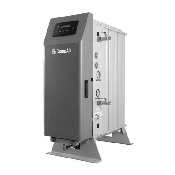
Page 10: Overview Of The Equipment
2.3 Overview of the equipment Key: Description Description User control interface Mains supply cable gland Analyser calibration port Column A pressure gauge Outlet port to buffer (G1»2) Column B pressure gauge Outlet pressure gauge inlet port from buffer vessel (G1/2) Outlet port (G1/2) Air inlet pressure gauge Cable glands... -
Page 11: Locating The Equipment
2.4 Locating the Equipment 2.4.1 Environment The equipment should be located indoors in an environment that protects it from direct sunlight, moisture, and dust. Changes in temperature, humidity, and airborne pollution will affect the environment in which the equipment is operating and may impair the safety and operation. It is the customers' responsibility to ensure that the environmental conditions specified for the equipment are maintained. -
Page 12: Installation And Commissioning
3 Installation and Commissioning Only competent personnel trained, qualified, and approved by Compair should perform installation, commissioning, service and repair procedures. 3.1 Recommended System Layout Description Description Description Description Compressor Dryer pre-filtration Generator Dust filter Wet air receiver Pre-treatment dryer... -
Page 13: Mechanical Installation
3.2 Mechanical Installation Fit one of the 1/2Ý ball valves supplied to the compressed air inlet port on the generator and attach the compressed air supply to this ball valve. Ensure that the valve is in the closed position. Fit another of the 1/2Ý ball valves supplied to the port marked “To Buffer vessel”. Install 1/2” NB / 16mm ID piping between the ball valve and the buffer vessel inlet port. -
Page 14: Electrical Installation
3.3 Electrical Installation A fully qualified electrical engineer must undertake all field wiring and electrical work in accordance with local regulations. In order to maintain the IP rating of the generator, all cables entering the electrical enclosure must do so through the dedicated cable glands located on the side of the generator. -
Page 15: Generator Supply
3.3.2 Dryer Supply If a Compair pre-treatment air dryer is used, it should be connected to the generator at the dedicated DIN rail terminals. Refer to the documentation provided with your dryer for additional information on installation requirements. -
Page 16: Operating The Generator
4 Operating the Generator 4.1 Overview of controls There are two control options available for this range of generators: A–Control with O Analyser. When fitted with an O analyser the controller provides a visual indication of the operating status of the generator. In addition to this the menu driven interface provides access to essential information such as oxygen purity, hour meters and fault logs. -
Page 17: Starting The Generator
4.2 Starting the generator Make sure that all connection points are secure and all of the ball valves on the system are closed. Open the ball valve (BV1) on the compressed air inlet port. Switch ‘ON’ the electrical power to the generator and wait for the controller to complete the initialisation routine. -
Page 18: Start Clean Up
The Start clean up cycle can be disabled within the customer settings menu (applies only to generators fitted with an O analyser), however Compair strongly recommend that the start up cycles remain enabled. 4.5 Economy Mode Economy mode is designed to switch the generator into standby mode when there is no demand for gas. -
Page 19: Menu Interface
4.6 Menu Interface The default menu displays the current operating status of the generator and, when running, indicates the purity of the gas delivered at the “Nitrogen Outlet” port. Note. The purity reading is for indication purposes only. The menu driven interface provides access to the essential operational parameters of the generator. From the default menu use the keys to scroll through to the desired menu and press The interface will automatically default back to the main operating menu if no key activity has been detected for one minute. -
Page 20: Password Protected Menus
> 25% (% generators) / O > 1.05% (ppm generators) zero drift error Contact Compair Service due Note. Any faults that are active when the power is switched off, and remain active when the power is re-applied, will cause a new entry to be... -
Page 21: Customer Settings
4.6.5 Customer Settings The customer settings menu contains all of the generator parameters that may be altered by the end user. The following example demonstrates the method of altering a parameter, however it is recommended that none of the parameters are altered until their functionality is fully understood. -
Page 22: Servicing
5 Servicing 5.1 Cleaning Clean the equipment with a damp cloth only and avoid excessive moisture around any electrical sockets. If required you may use a mild detergent, however do not use abrasives or solvents as they may damage the warning labels on the equipment. 5.2 Service Intervals The service operations should be performed at the hours run or fixed time intervals specified below (whichever occurs first). -
Page 23: Service Kits
Kit: Valve Overhaul 606510005 Air Inlet Valve Kit 608330002 Exhaust Valve Kit 608330002 Outlet Valve Kit 606510010 The valve overhaul (Service D) and all other repair and calibration work should be undertaken by a Compair trained, qualified and approved engineer. -
Page 24: Service Procedures
5.4 Service Procedures 5.4.1 Exhaust Silencer Replacement The exhaust silencer is located under the inlet manifold assembly. Unscrew the element from the exhaust port and discard. Fit the replacement element ensuring that it is fully engaged onto the pipe fitting and secure it hand tight. 5.4.2 Oxygen Cell Replacement Disconnect the oxygen cell lead from terminals 1, 2 and 3 (% vol. -
Page 26: Oxygen Analyser Calibration
(3), and the O Analyser calibration port (1). If a sample line other than the one provided by Compair is used ensure that it is suitable rated for the working pressure of the generator. - Page 27 5.5.1 Entering the calibrated level Select menu 3.2 to view the existing reading from the 0 analyser. O2 Calibration 4.95% Using the keys enter one of the following as applicable: •the purity of the calibration gas, O2 Calibration 5.00% •the purity reading from the independent analyser, O2 Calibration •Oxygen content of the compressed air (20.9%).
-
Page 28: Service Record
5.6 Service Record Generator Details Model Number: Serial Number Supply Voltage Commissioned By: Company Name Address: Telephone: Fax: Contact Name: Date of Commission: Serviced By Service Interval Date Comments Months (Hours) Print Sign 6 (4,000) 12 (8,000) 18 (12,000) 24 (16,000) 30 (20,000) 36 (24,000) 42 (28,000) -
Page 29: Troubleshooting
In the unlikely event that a problem occurs on the equipment, this troubleshooting guide can be used to identify the probable cause and remedy. Troubleshooting should only be attempted by competent personnel. All major repair, and calibration work should be undertaken by a Compair trained, qualified and approved engineer. Fault... - Page 32 Gardner Denver Deutschland GmbH Argenthaler Str. 11 55469 Simmern Deutschland Tel. ++ 49 (0) 6761 832-0 Fax. ++ 49 (0) 6761 832-409 Gardner Denver Ltd, Redditch Worcestershire Claybrook Drive Redditch B98 0DS Tel. ++49 (0) 1527 838 200 email:sales@compair.com...
Need help?
Do you have a question about the CN20033 and is the answer not in the manual?
Questions and answers