
Subscribe to Our Youtube Channel
Summary of Contents for Aqua Lung MRS III
- Page 1 MRS III Mobile Refill System for the Aqua Lung SEA (Survival Egress Air) Operation and Maintenance Manual January, 2016...
- Page 2 CHANGE RECORD Change No. Date Title or Description Change Made By 01-2010 5/2010 Add pages 35 & 36, Case dimensions, MRSIII weights, empty & full 02-2010 5/2010 Page 26, items #7 & #11, part number changed 03-2010 9/2010 New page 34, 955SSMM check vakve overhaul 01-2011 9/2011 New page 35, PRS6 overhaul...
-
Page 3: Table Of Contents
TABLE OF CONTENTS SECTION 1..............................1 DESCRIPTION OF UNIT ....................... 1 SECTION 2..............................1 CONFIGURATION ......................... 1 FIGURE 1, MRS III UNIT ....................1 SECTION 3 ............................2 PREPARATION FOR USE ......................2 FIGURE 2, CYLINDER HYDROSTAT STICKER ............2 SECTION 4 ............................ - Page 4 FIGURE 41, SUPPLY CYLINDER GAUGE ASSEMBLY ..........17 SECTION 16 ............................17 MRS III REGULATOR ........................17 REMOVING FROM MRS III ......................17 FIGURE 42, REGULATOR ASSEMBLY ............... 17 FIGURE 43, REGULATOR FITTINGS ................18 FIGURE 44, ACORN NUT ..................... 18 FIGURE 45, 1120KIT-1 DETAIL ..................
- Page 5 FIVE-YEAR MAINTENANCE KIT ..................... 33 955SSMM CHECK VALVE ......................34 PRS6............................... 35 REGULATOR ..........................36 MRS III FLOW DIAGRAM ......................... 37 PELICAN CASE, DIMENSIONS, TOP ...................... 38 PELICAN CASE, DIMENSIONS, BOTTOM ..................... 39 WARNING: This unit contains air under high pressure. Serious injury may result from misuse of this apparatus and the gas it contains.
-
Page 7: Section 1
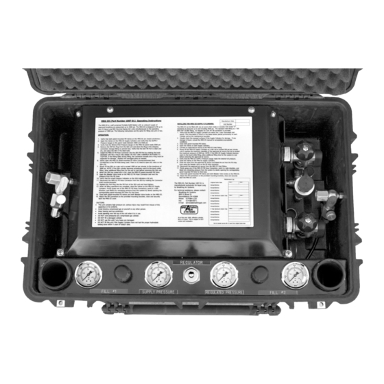
MRS III Mobile Refill System 1.0 DESCRIPTION OF UNIT: The MRS III is designed to refill the Aqua Lung Survival Egress Air (SEA) LV, MK1.5, MK2, MK2.5. It has an internal supply of two carbon fiber composite 4500psi cylinders and has two preset regulated 3000psi fill lines. The control panel will allow you to monitor the pressure in the supply cylinders, verify the preset regulated pressure and con- trol the filling of one or two SEA units. -
Page 8: Preparation For Use
5.3. Verify that the Regulated Pressure Gauge on the panel shows 3000psi, +/- 100 psi. If it does not, have a techni- cian that has been trained on the maintenance of the MRS III adjust the regulator, per 16.11. 5.4. Place the SEA in the cylinder holder. -
Page 9: Leaking Fittings
figure 5 figure 4 5.6. If the fitting leaks, remove from the SEA and inspect threads and O-ring for damage. Replace or repair parts as needed. 5.7. Bleeder valve (712) should be closed (figure 5). 5.8. Slowly open the panel mounted valve (YVA3010A), counterclockwise, that corresponds to the fill hose(s) used (figure 6). -
Page 10: 7.0 After Filling Is Completed
6.2.1. NOTE-THIS INSPECTION SHOULD CONFORM TO COMPRESSED ASSOCIATION PAMPHLET C-6.2 VISUAL INSPECTION OF FIBER REINFORCED HIGH PRESSURE CYLINDERS (EXTERNAL INSPECTION ). 6.3. This unit may be filled from any source of air that meets or exceeds CGA Grade “D” standards at pressures up to and including 4500psi. -
Page 11: 8.0 Warnings
7.2. Hold one of the fill hoses (HOS1) firmly and point the opening away from people (figure 12). 7.2.1. WARNING — AIM THE HOSE AWAY FROM YOURSELF AND FROM ANY OTHER PERSONNEL. HIGH PRESSURE AIR COMING INTO CONTACT WITH THE SKIN IS DANGEROUS. -
Page 12: Mrs Iii Maintenance
9.0 AFTER 1 YEAR, AND EVERY YEAR THEREAFTER..9.1. PARTS REQUIRED: 1-year overhaul kit ( Part Number MRSKIT1). 9.2. Open the Supply Cylinder valves (VAL1) and then slowly vent all air from the MRS III thru one of the fill hoses (HOS1). -
Page 13: Installing Seals
9.7. Lubricate the new seals generously with an approved non-toxic O-ring lubricant (Christo-lube), and slip the new seal on in the proper order. 9.7.1 It is recommended that you use tool set PRS21-8 (figure 15) to install the seals. 9.7.1.1 NOTE; INSTALL THE BACKUP PRS21-2 RINGS (PRS21-2) WITH THE CON- CAVE SIDE FACING THE O-RINGS... -
Page 14: Replacing Bleeder Valve Seat
10.0 REPLACING THE SEAT IN THE BLEEDER VALVE (712): 10.1. Unscrew the knob (712KNOB) and turn it over. The knob will pull through the bleeder keeper (59) by using a twisting motion. Using a sharp instrument get it under the edge of the white tip 712SSTIP (712SSTIP) and lift it out of its hole. -
Page 15: Removing Cylinders
11.3.1. WARNING: IF THESE DO NOT COME LOOSE WITH FIRM HAND STRENGTH, THERE MAY STILL BE AIR PRESSURE IN THE SYSTEM. VERIFY THAT ALL PRESSURE IS REMOVED BEFORE PROCEEDING. IF YOU CANNOT GET THIS LOOSE BY HAND YOU CAN USE SLIP JOINT PLIERS. DO NOT USE EXCESSIVE FORCE AS DAMAGE WILL RESULT. -
Page 16: Cylinder Inspection Guidelines
WHER FURTHER MAINTENANCE IS SCHEDULED OR REQUIRED, REMOVE THE UNIT FROM THE CASE. 13.1. With the lid closed and latched, turn the MRS III over. Remove the four screws from the back of the case. (figure 27). 13.2. Turn case over, open lid, and lift the unit out of the case (figure 28). -
Page 17: Removing Gauges
14.1.1. CAUTION: DO NOT CONTAMINATE THE MRS III BY USING CALIBRATION APPARATUS THAT WILL PUT OIL INTO THE SYSTEM. 14.1.2 To calibrate the gauges without removing them from the unit will require you make 3 separate connections. figure 28 figure 27 14.1.3 To test the supply pressure gauge you will need to... -
Page 18: Reinstalling Gauge
14.7. Install cylinder per reverse of 11.7 through 11.9.1. Reinstall top plate per reverse of 11.1. 14.8. The MRS III is now ready to pressure test. Close the supply cylinder valves (VAL1). Attach the approved source of CGA grade “D” Breathing Air to the refill port (DIN-F) and slowly pressurize to 1000psi. -
Page 19: Fill Valve Maintenance
15.4. After the 5-Year Maintenance is completed return the unit to Fill Valve service. 15.5. Fill valve (YVA3010A). 15.5.1. With valve open, remove the plastic center cap (YVA- KNOB-2) from the valve knob (YVAKNOB-1). Remove the nut (YVANUT) that holds the knob; using notched screwdriver from your SEA Tool Kit (PN9-47448). -
Page 20: Supply Cylinder Valves
32 The third is the gauge. 15.6.3. Supply Cylinder Valve (VAL1) rebuild procedures. 15.6.3.1. Remove supply cylinder (CYL1) from MRS III. 15.6.3.1.1. WARNING! ASSURE THAT THERE IS NO PRESSURE INSIDE THE CYLINDER. DO THIS BY CHECKING THE GAUGE LOCATED ON THE CYLINDER VALVE AND BY SLOWLY OPENING THE VALVE. - Page 21 Supply Cylinder Valve Assembly VAL1-20 VAL1-19 VAL1-7 VAL1-14 VAL1-15 VAL1-13 VAL1-16 VAL1-18 VAL1-15 VAL1-17 VAL1-6 VAL1-8 figure 34 15.6.3.2.1. NOTE! DO ALL WORK ON A CLEAN WORK SURFACE AS IT IS IMPORTANT THAT THIS VALVE BE KEPT CLEAN. 15.6.3.2.2. NOTE! REMOVING AND REINSTALLING THE VALVE INTO THE CYLINDER 100786 REQUIRES...
-
Page 22: Replacing Safety Disc
15.6.3.7. Remove the safety disc plug (VAL1-9) by using a 3/8” wrench or socket and turning counterclockwise until it is out (figure 38). Reinstallation torque is 70-80 inch- pounds (Non-critical, for reference only). If the disc does not come out with the plug, then turn the valve so that the opening is down and then tap it against the palm of your hand. -
Page 23: Mrs Iii Regulator
After the valve is leak free at 1000psi then pressurize to 4500psi and check for leaks. Otherwise, reinstall into system and test. After it VAL1-20 is leak free at 4500psi, reinstall into the MRS III and return to service. VAL1-8 figure 41 16.0... - Page 24 16.1.1. Place the unit face down on a clean work surface that has been covered with a pad or towel (to protect the unit from scratches on the face). Note the position of the regulator and plumbing. 16.1.2. Disconnect the two compression connections (PRS8 and MRS2) from the regulator’s inlet and outlet fittings (figure 43).
-
Page 25: Reassemble Regulator
the spring cap and turn it so that the inside portion is facing up. You will see an O-ring (1120KIT-3) and a smaller hex opening(1120KIT-2). Using an O-ring tool remove the O- ring and set it aside. Use a 5/8 socket 1120KIT1--1* 1120KIT1--3* wrench to remove the hex valve car-... -
Page 26: Mrs Iii Case
17.0 MRS III Case (1650) 17.1 The case for the MRS III is Pelican Products #1650. 17.1.1 This case is covered by “The Pelican Unconditional Lifetime Guarantee of Excellence”. If the case is damaged or broken contact Pelican Products at 800-473-5422 in the US except California or at 310-326-3311 outside of the US;... -
Page 27: Trouble Shooting Chart
TROUBLE SHOOTING CHART FOR THE MRS III PROBLEM ACTION O-ring at fill connection is damaged or missing. Replace O-ring. Leaks at connection to EBS. Contaminants on O-ring or sealing surface of fill port of EBS. Clean and inspect, repair if damage is present. - Page 28 Inspect fitting for damage, if damaged replace fitting. If fitting is loose: Pipe Thread fittings must be removed, have the Teflon tape replaced and reinstall with the same orientation as before. Leak at fitting Compression and Flare fittings can be tightened with- out need to remove them.
- Page 29 Replace case. Inspect metal frame: If damage is minor then the metal can be straightened MRS III metal frame is damaged using standard shop practices and hand tools. If damage is major replace MRS-III. Contact Breathing Air Systems to see if the supply MRS III exceeds 15 years from cylinders life has been extended beyond 15 years.
-
Page 30: Illustrated Parts Breakdown
Illustrated Parts Breakdown Mobile Refill System III (100701) FRONT OF UNIT page 24... - Page 31 page 25...
-
Page 32: Mrs Iii Unit Complete Assembly
END VIEW ITEM REQ ’D PART AQUALUNG DESCRIPTION PART NO. 1650 103201 CASE, PELICAN WITH WHEELS FRM1** 103202 TOP PLATE, 14¼” X 161/4” .125 ALUM. 5052-H32 FRM1** 103203 SUPPORT, 6” X 14 1/8” .125 ALUM. 5052-H32 PRS17 103204 GROMMET, 1.5”, ALTER FRM1** 103206 BRACKET 11½”... - Page 33 ELBOW, SS, FEMALE, ¼” FNPT STSS 103233 TEE, STREET, SST ¼” 103234 WASHER, FENDER ¼” SS HOSI 103236 HOSE, FILL MRS III CTXSS 103237 ELBOW, SS, ¼” FLARE X ¼” MNPT 103238 BLEEDER, INLINE MXF ALUMINUM PRS21 103239 FILL ADAPTER, #4 SAE X 14” FNPT...
-
Page 34: Inline Bleeder Assembly
PRS6-1 820040 O-RING PRS-2 820039 O-RING MRS3 ¼” FNPT X 1/8” TUBE STUB 712 INLINE BLEEDER ASSEMBLY (AQUA LUNG 103238) ITEM REQ’D PART NO. AQUALUNG DESCRIPTION PART NO. 103238 INLINE BLEEDER, COMES WITH 1, 2, AND 3 BELOW 712BODY 103318... -
Page 35: Fill Valve
Fill Valve FILL VALVE ASSEMBLY (YVA3010A) ITEM REQ’D PART NO. AQUALUNG DESCRIPTION PART NO. YVABODY 103282 VALVE BODY YVAKIT-5 * 103283 COPPER GASKET YVAKIT-1 * 103284 VALVE SEAT YVASTEM 103286 VALVE STEM YVAKIT-3 * 103287 THIN PACKING YVAKIT-4 * 103288 THICK PACKING YVABONNET 103289... -
Page 36: Supply Cylinder Valve
SUPPLY CYLINDER VALVE (#VAL1 or #103276) SUPPLY CYLINDER VALVE OVERHAUL KIT (VAL1KIT) SAFETY DISC GAUGE ASSEMBLY page 30... -
Page 37: Supply Cylinder Valve
SUPPLY CYLINDER VALVE PARTS BREAKDOWN ITEM REQ’D PART NO. AQUALUNG DESCRIPTION PART NO. VAL1 103276 SUPPLY CYLINDER VALVE VAL1-13 103296 COPPER GASKET VAL1-15 103297 VALVE STEM VAL1-16 103298 BONNET NUT VAL1-17 103299 LOCK SPRING VAL1-18 103301 VALVE NUT VAL1-7 103302 VALVE SEAT VAL1-5 103303... -
Page 38: Sea Fill Adapter
SEA FILL ADAPTER (PRS-21) ADAPTER OVERHAUL KIT (PRS21KIT) PRS21KIT ITEM REQ’D PART NO. AQUALUNG DESCRIPTION PART NO. PRS21KIT 100782 ADAPTER OVERHAUL KIT ITEMS 2,3,5 & 6 BELOW PRS21-1 103333 SPINDLE PRS21-3 100771 O-RING PRS21-2 100770 BACK-UP RING PRS21-4 103334 BODY PRS21-5 100772 SNAP RING... -
Page 39: One-Year Maintenance Kit
ONE-YEAR MAINTENANCE KIT MRSKIT1 (AQUA LUNG 100703) ITEM REQ’D PART NO AQUALUNG DESCRIPTION PART NO. PRS21-2 100770 BACKUP RING PRS21-3 100771 O-RING PRS21-5 100772 SNAP RING PRS21-6 100773 O-RING 712SSTIP 100774 100775 O-RING - CYL FILL ADAPTER VAL1-8 103307 O-RING... -
Page 40: 955Ssmm Check Valve
CHECK VALVE OVERHAUL (#955SSMM or #103246) ITEM REQ’D PART NO. DESCRIPTION 955KIT-1** SPRING (Cannot be purchased separately.) 955KIT-2** GASKET (Cannot be purchased separately.) 955KIT-3** BALL (Cannot be purchased separately.) 955KIT-4** O-RING (Cannot be purchased separately.) 955KIT Items 1, 2, 3, and 4 above. +** Part of valve rebuild kit. -
Page 41: Prs6
PRS6 OVERHAUL ITEM REQ’D PART NO. AQUALUNG DESCRIPTION PART NO. PRS6 PRS6-1 820040 O-RING PRS6-3 106058 STEM (Cannot be purchased separately.) PRS6-2 820039 O-RING PRS6-4 108657 HANDWHEEL (Cannot be purchased separately.) PRS6-5 054159 1/4”NPT FITTING (Cannot be purchased separately.) 347-1 103248 CGA 347 TO 1/4”... -
Page 42: Regulator
PRESET REGULATOR (1120) **Items 2, 3, and 4 are not available separately. They are included in overhaul kit 1120KIT, shown below. PRESET REGULATOR OVERHAUL KIT (1120KIT) ** 1120KIT-1 comes assembled in 1120KIT1--3** 1120KIT1--1** 1120KIT. Breakdown at left is shown SEAT PISTON for information only, in case parts be- 1120KIT1--2**... -
Page 43: Mrs Iii Flow Diagram
page 37... -
Page 44: Pelican Case, Dimensions, Top
page 38... -
Page 45: Pelican Case, Dimensions, Bottom
page 39...
Need help?
Do you have a question about the MRS III and is the answer not in the manual?
Questions and answers