Table of Contents
Advertisement
Advertisement
Table of Contents

Summary of Contents for YOKOGAWA GRVSW-660FA
- Page 1 Technical Network Switch for Vnet/IP Information TI 30A10A30-01E Yokogawa Electric Corporation TI 30A10A30-01E 2-9-32, Nakacho, Musashino-shi, Tokyo, 180-8750 Japan ©Copyright Sep. 2011 (YK) Tel.: 81-422-52-5634 Fax.: 81-422-52-9802 5th Edition Dec. 2016 (YK)
- Page 2 Blank Page...
- Page 3 Introduction Yokogawa has started providing reliable industrial network switches for Vnet/IP based on a new policy of “Yokogawa Certified Buyout.” These network switches, categorized as “Recommended products,” are supplied with the default configurations customized for Vnet/IP and they are referred to as the “Recommended Switch” in this document. The Recommended Switches consist of two types of switches;...
- Page 4 • All other company and product names mentioned in this document are trademarks or registered trademarks of their respective companies. • We do not use TM or ® mark to indicate those trademarks or registered trademarks in this document. All Rights Reserved Copyright © 2010, Yokogawa Electric Corporation TI 30A10A30-01E Dec. 26, 2016-00...
-
Page 5: Table Of Contents
Toc-1 Network Switch for Vnet/IP TI 30A10A30-01E 5th Edition CONTENTS Overview ....................1-1 Recommended Switch Models ................ 1-3 1.1.1 Managed Switches ................1-3 1.1.2 Unmanaged Switch ................1-4 1.1.3 How to use Unmanaged Switch ............1-5 SFP Module ......................1-7 1.3 Auto-Configuration Adapter (ACA) .............. - Page 6 Toc-2 Configuration Setup ................. 4-1 4.1 Preparation for setting ..................4-1 4.2 Summary of Command Line Interface (CLI) ..........4-3 CLI command ....................4-5 4.3.1 Confirm configuration (show running-config) ........4-5 4.3.2 Confirm system information (show sysinfo) ........4-6 4.3.3 Confirm port status (show port all) ............. 4-8 4.3.4 Restore to default (clear config factory) ...........
-
Page 7: Overview
• Customized default configuration for Vnet/IP • Service by Yokogawa engineer (*1) Yokogawa service engineers support the Recommended Switch in case it is used for Vnet/IP. Use it only for Vnet/IP, as other network connection is not guaranteed or supported. - Page 8 1. Overview Models and customized default configurations of Recommended Switches Both Layer2 switch (L2SW) and Layer3 switch (L3SW) models are lined up as the Recommended Switches. L2SW is a device to connect stations and modules within a Vnet/IP domain. L3SW is used for connecting Vnet/IP domains. Several models are available by input power type and port variation type.
-
Page 9: Recommended Switch Models
Table List of Managed Switches Power Ports Vnet/IP MS-Code Product Operating Supply Layer Mounting (Vender model name) Family Temp.(°C) RJ-45 GRVSW-660FA RS40 -40 to +70 DIN Rail (RS40-0009CCCCEDBPYY) GRVSW-663FA – (MACH104-20TX-F) 19” Rack MACH104 0 to +50 (1RU) GRVSW-664FA (MACH104-20TX-FR) GRVSW-665FA BUS1 L2SW –... -
Page 10: Unmanaged Switch
1. Overview 1.1.2 Unmanaged Switch The model of the Unmanaged Switch is as shown below. Table List of Managed Switches Ports Power Supply MS-Code (Vender Product Operating Layer Vnet/IP BUS Mounting model name) Family Temp.(°C) RJ-45 GR2SW-699FA BUS1, L2SW (SPIDER II Giga SPIDER II — -40 to +70 DIN Rail BUS2... -
Page 11: How To Use Unmanaged Switch
1. Overview 1.1.3 How to use Unmanaged Switch In order to simplify the drawings, BUS1 and BUS2 are drawn in a single line. Concept An Unmanaged Switch is not equipped with either configuration function or self-diagnostic function so that it can be placed only on the edge of the Vnet/IP network. HIS/ENG/SENG FCS/SCS Vnet/IP network... - Page 12 1. Overview Network structure not applicable Other than the edge-point or local connection of the network is not applicable. ENG/HIS ENG/HIS other switch (*1) other switch (*1) Two connections to other switches GR2SW Not Edge point Unmanaged Switch ENG/HIS Connecting to two (or more) switches is not allowed. F010105.ai Managed Switch or Unmanaged Switch Figure Not applicable network structure...
-
Page 13: Sfp Module
1. Overview SFP Module The SFP module is an optical transceiver to be installed in an SFP port of a Recommended Switch when connecting to another Switch with an optical fiber cable. SFP modules are hot-pluggable. The following models are offered for Recommended Switches. Select SFP modules from this list. Table SFP Modules for Recommended Switches Connectable... -
Page 14: Auto-Configuration Adapter (Aca)
1. Overview 1.3 Auto-Configuration Adapter (ACA) ACA (MS-Code: GRVACA-677FA) is a USB memory for the Recommended Switch for saving/ loading the configuration to change from the default configuration. If ACA is plugged-in, the Recommended Switch starts loading configuration automatically from ACA during startup. The configuration file can be backed-up on a file server, as the ACA is regarded as a USB memory when connected to a computer. -
Page 15: Hardware Specifications
2. Hardware Specifications Hardware Specifications RS40 Family 9 ports, DIN rail mounting model GRVSW-660FA (Vender model name: RS40-0009CCCCEDBPYY): L2SW, DC x 2 2.1.1 Name of Each Part and Descriptions Power Input/FAULT output Device status LEDs SFP port DIP switch USB interface V.24 interface Port 1 Port status LED Port 9 Port 8... - Page 16 2. Hardware Specifications Device status LEDs Four device status LED functions are as shown below. Table Device status LED function (RS40 Family) LED name Reaction Device status ON (Green) Normal operation P (Power) ON (Yellow) P1 or P2 power fail All power fail ON (Red) Detect device status error (*1) FAULT Normal operation ON (Green)
-
Page 17: Mounting
2. Hardware Specifications Shielding ground The front panel of the device is grounded via this ground screw. For the ground conductor, use a cable with a cross section of at least 1.0 mm 2.1.2 Mounting RS40 family device of the Recommended Switch is designed for mounting onto a 35 mm DIN rail as shown in the figure below. -
Page 18: Mach104 Family
2. Hardware Specifications MACH104 Family 24 ports, 19-inch rack mounting model GRVSW-663FA (Vender model name: MACH104-20TX-F): L2SW, AC x 1 GRVSW-664FA (Vender model name: MACH104-20TX-FR): L2SW, AC x 2 2.2.1 Name of Each Part and Descriptions Device status LEDs RJ-45 Port V.24 interface SFP Port USB interface Port status LEDs FAULT output Power input (P1) Power input (P2) F020201.ai... - Page 19 2. Hardware Specifications Device status LEDs Four device status LED functions are as shown below. Table Device status LED function (MACH104 Family) LED name Reaction Device status ON (Green) Normal operation (*1) P (Power) ON (Yellow) P1 or P2 power fail All power fail ON (Red) Detect device status error (*2) FAULT Normal operation...
-
Page 20: Mounting
2. Hardware Specifications 2.2.2 Mounting MACH104 family device of the Recommended Switch is designed for mounting on a 19-inch rack cabinet. Measure the 19-inch rack’s depth to let a main cable and any power supply cables to fit from the back, and the data cables from the front. Install the sliding/mounting rails in the 19-inch switch cabinet as instructed by the manufacturer, and make sure the device is resting on both rails to protect the device from vibrating. - Page 21 2. Hardware Specifications MAR1040 Family 16 combo ports, 19-inch rack mounting model L2SW models GRVSW-665FA (Vender model name: MAR1040-4C4C4C4C9999EM9HPYY) : AC x 1 GRVSW-666FA (Vender model name: MAR1040-4C4C4C4C9999EMMHPYY) : AC x 2 GRVSW-667FA (Vender model name: MAR1040-4C4C4C4C9999ELLHPYY) : DC x 2 L3SW models for BUS1 GRVSW-668FA (Vender model name: MAR1040-4C4C4C4C9999EM9HRY1) : AC x 1 GRVSW-669FA (Vender model name: MAR1040-4C4C4C4C9999EMMHRY1) : AC x 2 GRVSW-670FA (Vender model name: MAR1040-4C4C4C4C9999ELLHRY1) : DC x 2...
-
Page 22: Ti 30A10A30-01E Dec. 26,
2. Hardware Specifications Power input (3 pin terminal block) The redundant power unit models have two terminal blocks for P1 and P2 power input. MAR1040 family is powered by the terminal block regardless of DC or AC. The pin function is as shown below. Table Power Input Pin Function (MAR1040 Family) AC power input DC power input Connection... - Page 23 2. Hardware Specifications Device status LEDs Four device status LED functions are as shown below. Table Device status LED function (MAR1040 Family) LED name Reaction Device status ON (Green) Normal operation (*1) P (Power) ON (Yellow) P1 or P2 power fail All power fail ON (Red) Detect device status error (*2) FAULT Normal operation...
- Page 24 2-10 2. Hardware Specifications SFP port SFP port has a plug-in slot for an SFP module. Plug the SFP module into the slot to use Vnet/IP optical connection. The SFP port is for dual purpose (RJ45/SFP) combo port. The combo port will select SFP interface automatically when the SFP module is installed. Port status LED ...
-
Page 25: External Dimensions
In order to prevent wrong network cable connections to the operating system, the cabinet must be protected by a security lock key. 2.3.3 External Dimensions Unit: mm 342.0 19.3 444.0 19.3 HIRSCHMANN MAR1040 YOKOGAWA V net/I P 43.9 31.75 V. 2 4 FAULT 462.6 F020302.ai Figure External Dimensions (MAR1040 Family) TI 30A10A30-01E Dec. 26, 2016-00... -
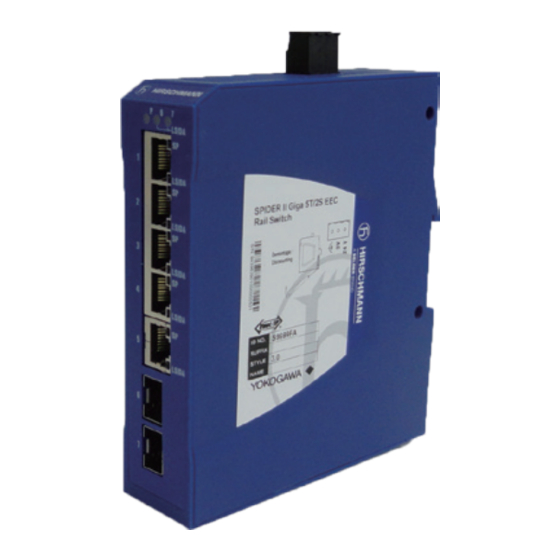
Page 26: Spider Ii Family (Unmanaged Switch)
2-12 2. Hardware Specifications 2.4 SPIDER II Family (Unmanaged Switch) 7 ports, DIN rail mounting model GR2SW-699FA (Vendor model name: SPIDER II Giga 5T/2S EEC): L2SW, DC x 1 2.4.1 Name of Each Part and Descriptions SFP port status LEDs Power input and ground (Port6) (Port7) Device status LED Port1 RJ-45 port status LEDs RJ-45 port Port5 Port6 SFP port... - Page 27 2-13 2. Hardware Specifications Device status LED The device status LED functions are as shown below. Table Device Status LED Function (SPIDER II Family) LED name Reaction Device Status ON (Green) Normal Operation P (Power) All power fail SFP port status LEDs Port status LEDs for F/O ports on the device’s top edge of the front display port-related information.
-
Page 28: Mounting
2-14 2. Hardware Specifications 2.4.2 Mounting SPIDER II Family device of the Recommended Switch is designed for mounting onto a 35 mm DIN rail, as shown below. Attach the the device’s upper snap-in guide into the DIN rail and press it down against the DIN rail until it snaps into place. -
Page 29: Hardware Information
2-15 2. Hardware Specifications Hardware Information 2.5.1 Hardware Specification List Hardware specifications of the Recommended Switches are as shown below. Table Hardware Specifications List Unmanaged Managed Switches Switch SPIDER II RS40 Family MACH104 Family MAR1040 Family Family ITEM AC Input AC Input AC Input AC Input DC Input DC Input DC Input Single Redundant Single Redundant... -
Page 30: Wiring To Terminal Block
2-16 2. Hardware Specifications 2.5.2 Wiring to Terminal Block Sleeve attachment for cables For safe wiring, make sure to use a sleeve for a cable connected to the terminal block for Power Input or FAULT Output. Assemble the edge of the cable into the sleeve. Use appropriate sleeves for applicable cables. - Page 31 2-17 2. Hardware Specifications Cable clamp to terminal block As for wiring for a cable clamp to a terminal block, see below. -/N +/L F020402.ai Figure Cable clamp to terminal block The use of drivers which comply with DIN 5264B standard (flat blade screw driver with tip thickness 0.6 mm, axis radius 3.5 mm) is recommended when connecting cables. Loosen the pressure clamp of the terminal block by turning the screw counterclockwise.
-
Page 32: Configuration Backup/Restore
3. Configuration Backup/Restore Configuration Backup/Restore This section describes the backup and restoration procedure of configuring the Managed Switches by using Auto-Configuration Adapter (ACA). For restoring the Managed Switches to the default configuration, see “clear config factory” command in section 4.3.4. 3.1 Configuration File Architecture The current configuration of the Managed Switch is based on the “running-config” file in the system RAM. When the ACA is disconnected, the Managed Switch boots up with “startup-config” file in the non- volatile RAM (NVRAM), and the “running-config”... -
Page 33: Configuration Backup To Aca
3. Configuration Backup/Restore 3.2 Configuration Backup to ACA The configuration backup procedure using an ACA is described as below. 1) Clear the ACA device. Connect the ACA to a computer. Delete all files in the ACA by file operation on the computer. Save the files which will be reused before deleting. 2) Disconnect the ACA from the computer after conducting the common USB device removal procedure. -
Page 34: Configuration Setup
4. Configuration Setup Configuration Setup In a typical Vnet/IP network design based on the “Vnet/IP Network construction guide,” Managed Switches require no modification from the default configuration except for some applications. This section describes some basic Command Line Interface (CLI) Commands for setting up and confirming the Vnet/IP configuration. The Managed Switches also support many other CLI commands not described in this document. For more information, refer to the CLI Reference Manual in the attached disc media of the Managed Switch. This is not applicable to the Unmanaged Switch. 4.1 Preparation for setting For CLI control, connect a Managed Switch to a computer using a terminal cable. Use a terminal software such as “Teraterm” to emulate VT-100 terminal with the computer. The connection setup parameters for the terminal software are as shown below. - Page 35 4. Configuration Setup The following login message will be displayed after booting up when the terminal software is correctly set. No line will be displayed on the terminal software if it runs after the boot up of the Managed Switch. In such case, the login message is displayed by hitting the “Enter” key. Key-in the following underlined characters in the login window.
-
Page 36: Summary Of Command Line Interface (Cli)
4. Configuration Setup 4.2 Summary of Command Line Interface (CLI) The Command Line Interface (CLI) has several command modes. Available CLI commands vary depending on the command modes. The structure of the command modes is as shown below. For changing the command mode, key-in the command over each of the arrowed line. User Exec mode is the starting point just after log-in. - Page 37 4. Configuration Setup The Command Line Interface supports following functions. Command input assistant function Once enough letters are entered to uniquely identify a command name, press the “Tab” key to let the system complete the rest of the command name. Command/Parameters list choices display function When a question mark “?” is entered, a list of possible command keywords or parameters is displayed.
-
Page 38: Cli Command
4. Configuration Setup CLI command Basic commands to change/confirm the configuration of Managed Switch are introduced in this section. To save the modification for on-going usage, copying “running-config” to “startup- config” in NVRAM is required. (See section 4.3.5) 4.3.1 Confirm configuration (show running-config) To display the current setting of the different protocol packages supported by the switch, use “show running-config”... -
Page 39: Confirm System Information (Show Sysinfo)
4. Configuration Setup 4.3.2 Confirm system information (show sysinfo) To confirm the system information of the Managed Switch, use “show sysinfo” command. The “show sysinfo” command is available in “Privileged Exec” mode or “User Exec” mode. A sample display of “show sysinfo” command execution is as shown below. (Hirschmann MACH) #show sysinfo Last Alarm 1........ - Page 40 4. Configuration Setup Key parameters in the above display are explained as below. Alarm The latest present alarm is indicated. The alarm condition is the same as for a signal contact. (In the above example, the device detects P2 power failure.) System IP Address ...
-
Page 41: Confirm Port Status (Show Port All)
4. Configuration Setup 4.3.3 Confirm port status (show port all) To confirm all port status, use “show port all” command. This command is available in “Privileged Exec” mode or “User Exec” mode. A sample display of “show port all” command execution is as shown below. (Hirschmann MACH) #show port all Admin Physical Physical... - Page 42 4. Configuration Setup Physical Status The link speed and duplex mode state of each link up port are displayed as follows. [10 Half]: 10Mbps, Half duplex [10 Full]: 10Mbps, Full duplex [100 Half]: 100Mbps, Half duplex [100 Full]: 100Mbps, Full duplex [1000 Full]: 1000Mbps, Full duplex...
-
Page 43: Restore To Default (Clear Config Factory)
4-10 4. Configuration Setup 4.3.4 Restore to default (clear config factory) To restore the Recommended Switch to default configuration, use “clear config factory” command. This command is available in Privileged Exec mode. By using this command, the device is restored to factory default for Vnet/IP. Press “y” key to the confirmation message for execution of this command. (Hirschmann Railswitch) #clear config factory WARNING: ALL configuration data will be erased from non volatile storage! This may take up to a minute depending on your configuration. -
Page 44: Port Disable For Unused Port (Shutdown)
4-11 4. Configuration Setup 4.3.6 Port Disable for unused port (shutdown) To disable particular ports such as unused ports, use “shutdown” command in “Interface Config” mode. The following example shows the commands for disabling port 5. (Hirschmann Railswitch) >enable (Hirschmann Railswitch) #configure (Hirschmann Railswitch) (Config)#interface 1/5 (Hirschmann Railswitch) (Interface 1/5)#shutdown F040306.ai Figure Example of “shutdown” command display To reactivate the disabled port, use “no shutdown”... -
Page 45: Cascaded Domain Connection By L3Sw
4-12 4. Configuration Setup 4.3.8 Cascaded domain connection by L3SW This section explains a sample configuration for a cascaded domain connection by the Recommended L3SWs. A sample diagram of the Vnet/IP network is as shown below. (1) Change IP address for the cascaded port Get rid of IP address conflict 192.168.1.253 192.168.3.253... - Page 46 4-13 4. Configuration Setup Setting procedure For the cascaded domain connection, an example of a setting procedure is as shown below. IMPORTANT The L3SW from live network must be segregated before executing this procedure unless otherwise the Vnet/IP network will become unstable caused by the address conflict during an incomplete configuration. (1) Assign unique IP address to cascaded port of Recommended L3SW To change the assigned IP address of the Recommended L3SW port, use “ip address”...
- Page 47 4-14 4. Configuration Setup (2) Disable unused ports not connected to any domain To disable unused ports, use “shutdown” command in “Interface Config” mode. The following example shows the commands to disable the ports 2 and 4 to 16 of L3SW-1. (Hirschmann MACH) >enable (Hirschmann MACH) #configure (Hirschmann MACH) (Config)#interface 1/2 (Hirschmann MACH) (Interface 1/2)#shutdown (Hirschmann MACH) (Interface 1/2)#exit (Hirschmann MACH) (Config)#interface 1/4...
- Page 48 4-15 4. Configuration Setup Setting up additional domain To add a domain in a cascaded Vnet/IP domain network, enable the L3SW port for additional domain connection. The following diagram shows an example of Vnet/IP network where Domain 2 is added. Enable port 2 for additional Domain.
-
Page 49: Configuring A Ring Network
4-16 4. Configuration Setup 4.3.9 Configuring a ring network This section describes how to configure a ring network using network switches for Vnet/IP. Setting an L2SW for MRP ring network The example below describes how to configure an L2SW in a ring network using an MRP. The ring part must be wired after all the settings of the L2SW are done. - Page 50 4-17 4. Configuration Setup Setting FAULT terminal action In case an L2SW is assigned as a ring manager, FAULT terminal output has to be set when a ring network failure is detected. For how to add the ring network status as a subject for monitoring of the FAULT terminal (*1) is explained as follows.
-
Page 51: Appendix 1. Default Configuration
App.1-1 Appendix 1. Default configuration Appendix 1. Default configuration The Recommended Switches are provided with the customized default configuration for Vnet/IP to connect to Vnet/IP network as described in the summary below. For Recommended L2SW, the customized default configuration is as shown below. • Auto-negotiation: Enable •... - Page 52 App.1-2 Appendix 1. Default configuration For more information of the default configuration, the example of “show running-config” display is shown below. In the list, those blank or repeating lines are omitted. RS40 (L2SW) family default configuration The running-config on RS40 (LS2W) family default configuration (1/2) (Hirschmann Railswitch) #show running-config !Current Configuration: !Customized factory setting active !Parameter string escape handling \, 1 !Characters to be preceded with escape char (\): \, !, ", ', ? !System Description "Hirschmann Railswitch"...
- Page 53 App.1-3 Appendix 1. Default configuration The running-config on RS40 (LS2W) family default configuration (2/2) !Hirschmann HIPER Ring !LLDP (IEEE802.1AB Link Layer Discovery Protocol) !Media Redundancy Protocol (IEC 62439/Ed1.0, MRP) !No MRP domains exist. !No entries in alarm table !MAC/IP Based Port Security !ProfinetIO !Hirschmann Precision Time Protocol (PTP, IEEE 1588) !Hirschmann Ring Coupling !Note: master/slave (also for single) part of configuration determined by management !Hirschmann Signal Contacts...
- Page 54 App.1-4 Appendix 1. Default configuration MACH104 (L2SW) family default configuration The running-config on MACH104 (LS2W) family default configuration (1/2) (Hirschmann MACH) #show running-config !Current Configuration: !Customized factory setting active !Parameter string escape handling \, 1 !Characters to be preceded with escape char (\): \, !, ", ', ? !System Description "Hirschmann MACH" !System Version L2P-06.0.01 Build: 2010-09-24 21:19 vlan database exit network protocol none...
- Page 55 App.1-5 Appendix 1. Default configuration The running-config on MACH104 (LS2W) family default configuration (2/2) !Hirschmann Precision Time Protocol (PTP, IEEE 1588) ptp clock-mode v1-simple-mode !Hirschmann Ring Coupling !Note: master/slave (also for single) part of configuration determined by management !Hirschmann Signal Contacts signal-contact 1 mode auto signal-contact 2 mode auto !Hirschmann SNMP Access Control !SNTP !Hirschmann Broadcast Limiter !Hirschmann Temperature Limit Settings...
- Page 56 App.1-6 Appendix 1. Default configuration MAR1040 (L2SW) family default configuration The running-config on MAR1040 (LS2W) family default configuration (1/2) (Hirschmann MACH) #show running-config !Current Configuration: !Customized factory setting active !Parameter string escape handling \, 1 !Characters to be preceded with escape char (\): \, !, ", ', ? !System Description "Hirschmann MACH" !System Version L2P-06.0.01 Build: 2010-09-24 20:19 vlan database exit network protocol none...
- Page 57 App.1-7 Appendix 1. Default configuration The running-config on MAR1040 (LS2W) family default configuration (2/2) !Media Redundancy Protocol (IEC 62439/Ed1.0, MRP) !No MRP domains exist. !No entries in alarm table !MAC/IP Based Port Security !ProfinetIO !Hirschmann Precision Time Protocol (PTP, IEEE 1588) !Hirschmann Ring Coupling !Note: master/slave (also for single) part of configuration determined by management !Hirschmann Signal Contacts signal-contact 1 mode auto...
- Page 58 App.1-8 Appendix 1. Default configuration MAR1040 (L3SW) family default configuration This is an example of the Recommended L3SW for BUS1 display. As for the Recommended L3SW, two types are available with different default configuration for BUS1 and BUS2. The difference is the IP address assigned to each port. See the default IP address list described at the top of this appendix.
- Page 59 App.1-9 Appendix 1. Default configuration The running-config on MAR1040 (LS3W) family default configuration (2/3) !Address Conflict Detection !Bridge Address Learning !Maximum size of frame (packet size) !Bridge Address Relearn Detection !Bridge Address Relearn Threshold !Bridge Duplex Mismatch Detection !VLAN Learning !Hirschmann DHCP Relay !Hirschmann Device Status device-status monitor power-supply-2 ignore !DHCP Server !DHCP Server pools !Ethernet/IP !Power over Ethernet (IEEE 802.3af)
- Page 60 App.1-10 Appendix 1. Default configuration The running-config on MAR1040 (LS3W) family default configuration (3/3) no spanning-tree !Tracking !IGMP Snooping set igmp set igmp query-ports-to-filter enable ip igmp no ip igmp software-dscp-value ip pimdm ip multicast router ospf exit router rip enable update-timer 1 exit exit F0A0109.ai Note: The “device-status monitor power-supply-2 ignore” line is displayed only for single power unit model. TI 30A10A30-01E Sep.
-
Page 61: Appendix 2. Vlan-Based Routing
App.2-1 Appendix 2. VLAN-based routing Appendix 2. VLAN-based routing The Recommended L3SW is set to “Port-based routing” configuration by default and it supports “VLAN-based routing” configuration to assign some ports to a same subnet instead of L2SW in the domain. However, the VLAN-based routing configuration requires complicated settings. For establishing a simplified Vnet/IP network, Port-based routing configuration is recommended for L3SW. - Page 62 App.2-2 Appendix 2. VLAN-based routing Create VLANs Next step is to create four VLANs for VLAN-based routing, using “vlan” commands in VLAN mode. The following example shows commands to create four VLANs and assign VLAN IDs 11 to 14 respectively.
- Page 63 App.2-3 Appendix 2. VLAN-based routing VLAN participation per port Once the VLANs are created, assign them to each port. The following example shows commands to assign port 1 to VLAN11. (Hirschmann MACH) (Config)#interface 1/1 (Hirschmann MACH) (Interface 1/1)#vlan pvid 11 (Hirschmann MACH) (Interface 1/1)#vlan participation exclude 1 (Hirschmann MACH) (Interface 1/1)#vlan participation include 11 (Hirschmann MACH) (Interface 1/1)#set igmp forward-all Forward All enabled for port 1/1.
- Page 64 App.2-4 Appendix 2. VLAN-based routing Virtual router port configuration for VLAN IP address and set unicast/multi-cast routing configuration parameters for virtual router port of each VLAN are to be assigned. The following example shows commands to set the virtual router port configuration. In this example, IP address of interface 9/1 for VLAN11’s virtual router port is assigned to 192.168.1.253/24 of the domain 1.
- Page 65 App.2-5 Appendix 2. VLAN-based routing Confirm VLAN-based routing configuration For more information of the example of the VLAN-based routing configuration, “show running- config” display is as shown below. Confirm if the modified configuration are valid by comparing the following examples. VLAN-based routing configuration (1/4) (Hirschmann MACH) #show running-config !Current Configuration: !Parameter string escape handling \, 1 !Characters to be preceded with escape char (\): \, !, ", ', ?
- Page 66 App.2-6 Appendix 2. VLAN-based routing VLAN-based routing configuration (2/4) interface set igmp forward-all vlan pvid 11 vlan participation exclude 1 vlan participation include 11 exit (S n i p) i n t e r f a c e 1 / 2 t o 1 / 4 - - - r e p e a t i n g t h e s a m e s e t t i n g . interface set igmp forward-all vlan pvid 12...
- Page 67 App.2-7 Appendix 2. VLAN-based routing VLAN-based routing configuration (3/4) !Address Conflict Detection !Bridge Address Learning !Maximum size of frame (packet size) !Bridge Address Relearn Detection !Bridge Address Relearn Threshold !Bridge Duplex Mismatch Detection !VLAN Learning !Hirschmann DHCP Relay !Hirschmann Device Status device-status monitor power-supply-2 ignore !DHCP Server !DHCP Server pools !Ethernet/IP...
- Page 68 App.2-8 Appendix 2. VLAN-based routing VLAN-based routing configuration (4/4) users passwd admin :v1:81449548fb49a99b06ee86ebedf5a85f28ba5f2f9871a69a62caf05f4623e4c2: users snmpv3 authentication admin md5 users snmpv3 encryption admin des :v1:81449548fb49a99bbf6dd760dfde0db4e95bb065aca48c55a23d906acc20051a: users passwd user :v1:81439e52f35ecc4b248bb9be2bd8825f0e3067dc4aa498f7670ad5dc2cc07445: users snmpv3 authentication user md5 users snmpv3 encryption user des :v1:81439e52f35ecc842032502ec1b91b2873f525d9f917640184652661f4c8a829: lineconfig exit no spanning-tree spanning-tree configuration name "00-80-63-AE-E3-00"...
-
Page 69: Appendix 3. Reuse Of Existing Multimode Optical Fiber Cable
App.3-1 Appendix 3. Reuse of Existing Multimode Optical Fiber Cable Appendix 3. Reuse of Existing Multimode Optical Fiber Cable Compared with single-mode optical fiber, multimode optical fiber has a parameter of modal bandwidth that limits the transmission distance for high speed signal. We strongly recommend single mode optical fiber for Vnet/IP that requires high speed 1-Gbps communication. In cases where existing multimode optical fiber cables have to be reused by reason of the cable installing cost, follow the precautions shown below, depending on the corresponding cable lengths. - Page 70 App.3-2 Appendix 3. Reuse of Existing Multimode Optical Fiber Cable Performance checks (1) Optical attenuation Check that the total loss of the optical power at 1310 nm wavelength by using a stabilized light source and an optical power meter. The total loss must not exceed 5 dB. (2) Quality of signal transmission affected by the modal bandwidth Perform continuous PING test with 1,500 byte packet length between a pair of L2SW connected to the existing fiber cable with using GRVSFP-674FA (M-FAST SFP-MM/LC).
-
Page 71: Appendix 4. Precautions For Long-Haul Optical Fiber Connection
App.4-1 Appendix 4. Precautions for Long-haul Optical Fiber Connection Appendix 4. Precautions for Long-haul Optical Fiber Connection Distance between the two arbitrary stations in a domain The specification of Vnet/IP has a limitation of communicable distance between the two arbitrary stations in a domain. The maximum distance (40 km) is too short for the network configuration requiring long-haul optical fiber connection. - Page 72 Blank Page...
- Page 73 Revision Information Title: Network Switch for Vnet/IP Manual No.: TI 30A10A30-01E Sep. 2011/1st Edition Newly published Nov. 2013/2nd Edition 2.2.1 Revised a description on AC power cable. Sep. 2014/3rd Edition 1.1.2 Descriptions on SPIDER II, Unmanaged Switch, are added. 1.1.3 Ditto. Ditto. All pages Typographical and grammatical errors are corrected.
- Page 74 Written by Yokogawa Electric Corporation Published by Yokogawa Electric Corporation 2-9-32 Nakacho, Musashino-shi, Tokyo 180-8750, JAPAN Subject to change without notice.
Need help?
Do you have a question about the GRVSW-660FA and is the answer not in the manual?
Questions and answers