Table of Contents
Advertisement
Advertisement
Table of Contents

Related Manuals for Belmash SDM-2000


Summary of Contents for Belmash SDM-2000
- Page 1 1 ...
-
Page 2: Table Of Contents
CONTENTS 1. Declaration of conformity ЕС/ЕЕА 2. Intended use 3. General information 4. Main parameters 5. List of standard equipment 6. Basic components 7. Machine structure 8. Safety issues 9. Marking and packing 10. Setting-up procedures 11. Basic operations 12. Maintenance and repair 13. -
Page 3: Declaration Of Conformity Ес/Ееа
01/222-2** _____________________________________________ * - for machines BELMASH SDM-2000 ** - for machines BELMAS SDM-2200, BELMASH SDM-2500 Director _____________ D. V. Shorikov Conformity certificates are stored at the address: Zavod Belmash JLLC, Slavgorodskiy Proezd, 37 Republic of Belarus, 212000, Mogilev. 3 ... -
Page 4: Intended Use
The power of the machine is supplied by a single-phase AC with an earthed positive earth. BELMASH SDM-2200 и BELMASH SDM-2500 machines shall be used in the electrical grids with a nominal impedance z =0,354 ohm. -
Page 5: Main Parameters
Main parameters are specified in the Table 1. Table 1 Parameters № Name BELMASH BELMASH BELMASH SDM-2000 SDM-2200 SDM-2500 Max. planing width per pass, mm Range of planing depth per pass, mm 0÷3 0÷3 0÷3 Max. height of the work piece pressed by a holding down device, up to, mm Max. -
Page 6: List Of Standard Equipment
5. LIST OF STANDARD EQUIPMENT Table 2 Quantity, pсs № Item Name BELMAS BELMASH BELMASH SDM-2000 SDM-2200 SDM-2500 Devices, tools, fencing Portable multifunctional woodworking machine Fencing of saw blade and disc cutter 28, 29 together with the splitting knife 11, 12... -
Page 7: Basic Components
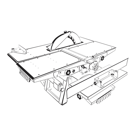
6. BASIC COMPONENTS Fig. A Planing function 1 – Knife block 2 – Loading table 3 – Outfeed table 7 – Knife’s block fencing 8 – Swing bracket for knife’s block fencing 9 – Clip for fixing of knife’s block fencing 10 –... - Page 8 В1 40 45 Fig. В1, B2 Cutting function 12 – Gib stick of angular bump (vertical) 35 – Angular cross cutting scale 24 – Pipe for cutting wastes 36 – Flywheel for bum fixation 25 – Saw blade 37 – Cutting depth scale 26 –...
- Page 9 Fig. С Milling with disc cutter 11 – Angular bump (vertical) 12 – Gib stick of angular bump (vertical) 27 – Stick for lifting and lowering of saw blade 29 – Fencing of saw blade / disc cutter above the table level 41 –...
- Page 10 Fig. D End milling function 11 – Angular bump (vertical) 12 – Gib stick of angular bump (vertical) 16 – Fixing handwheels of angular support (vertical) 46 – Milling table 47 – End milling cutter (not included in the scope of delivery) 48 –...
- Page 11 23 64 65 Fig. Е Planing with holding down device 4 – Lever-stick for lifting and lowering the loading table and transferring the machine 5 – Lever-stick for lifting and lowering the outfeed table and transfer machine 6 –...
-
Page 12: Machine Structure
7. MACHINE STRUCTURE The machine is an electromechanical device. The woodworking machines are powered with the help of asynchronous electromotor. Rotation from the motor to the knife block (outlet end of the knife block) and saw blade is performed with the help of multiple vee belt drive. The belt covers driving pulley and two driven pulleys. -
Page 13: Safety Issues
8. SAFETY ISSUES Before starting to use the machine the user shall take into account his physical state, qualification and complexity of tasks. Persons operating the woodworking machines must be at least 18 years of age and must study the operating manual. IT IS FORBIDDEN: ... - Page 14 To ensure high-quality and safe operation, the cutting part of the working tool must be sharp and clean. Follow the instructions to replace the accessories. 8.1 Workplace requirements The workplace should be determined taking into account the location of the workpieces , direction of their movement, and junkyard location;...
- Page 15 The figures of equivalent and ceiling sound level (p. 3) are the levels of radiations but are not necessarily the safe operating levels. Despite there is a correlation between levels of radiation and noise impact, they can be reliably used to determine if further protection measures will be required.
-
Page 16: Marking And Packing
Keep your hands at a safe distance from the cutting place. The workpiece supply should be steady (without jerks). The table speed should provide the smooth running of the machine to avoid overloading. To process short workpieces (with length less than 300 mm), use special devices for secure workpiece supply (pushers). -
Page 17: Setting-Up Procedures
Consider the tool sizes and do not use adapters for them. Use the tool recommended by the manufacturer. When working, consider the maximum allowable finished dimensions. Information on the types of processing is listed on the label on the fencing of the 30 (Fig. B1) saw blade below the table level. - Page 18 Install fencing of saw blade together with the splitting knife (p. 10.1.2); Install the device for angular cross cutting (p. 10.1.3); Install the knife’s block fencing together with the bracket (p. 10.1.4); Install the milling table (p. 10.1.5), in case you are going to perform planning with end mill cutter or drilling;...
- Page 19 This requires inserting the saw blade to the maximum cutting depth. The splitting knife shall be placed symmetrically in the center in the plane of the saw blade, providing radial distance between the splitting knife 28 and the crown of the saw blade equal to 5 mm (Fig. H). It is achieved by moving the washers with screw nuts 59, 60 (Fig.
- Page 20 the thickness less than 60 mm. It is shipped dismounted. The kit of parts (Table 2) is packed in a separate box. The assembly of the holding down device is performed as shown in the Figure J. To fix the holding device, use screws 23 and 8-mm washers. Fig.
- Page 21 Adjust the knives by tightening / unscrewing the screws 71 so that the knife edge touch the ruler 12, mounted on the receiving table 3 (Fig. N) 69 70 Fig. L Knife mounting 1 – cutter block; 1а – block casing; 69 – knife holder; 70 – slicing blade; 71 – fixing screw for the knife holder Fig.
-
Page 22: Basic Operations
installation. If required, repeat the installation again. The cutting edge of properly installed knives should touch (up to 0,1 mm) the lower edge of the ruler 12 during cutting block rotation. 10.4 Machine startup Machine startup is performed with the help of the switcher after adjusting the processing type. - Page 23 11.1.1 Installing the planning table The loading 2 and outfeed 3 tables should be installed at the level of the slicing blade cut (Fig. O). To get that done: loose the flywheels 6; pull the locking clip 52 (horizontally) by holding it from the bottom, and lower the tables by moving the lever-sticks 4 and 5 down against stop;...
- Page 24 When the work is completed and during work breaks, the fencing 8 should totally close the cutter block. Fig. P Using the fencing 7 – fencing; 7а – arrows; 10 – flywheel for clip fixation, 65 – knife’s end block fencing 11.1.4 Installing the ruler in the planning mode The ruler 12 ready-fitted with the angular bump 11 is designed for positioning of the workpiece relative to the cutter block.
- Page 25 To install the ruler 12 at an angle, it is necessary to loosen two flywheels 17, install the ruler along the scale 13 at the desirable angle, and tighten the flywheels 17. The ruler 12 should to be adjacent to the outfeed 3 table (at any turning angle). It requires loosening the screws with nuts 11c, moving the ruler along the slots11a of the angular bumps 11 to the necessary extent, tightening the screws with nuts 11c.
- Page 26 with the cutting table 26 (the lines "close" on scale will coincide). To do so, unscrew the flywheels 6, lift the lever-stick 4 and 5 (Fig. E), and then tighten the flywheels again 6. The locking clip 52 will automatically block the planing tables 2 and 3. 11.2.2 Installing the cutting depth Fig.
- Page 27 workpiece to the bump 34, move the device along the guideway 26a in the direction of the saw blade. 26а Fig. Т The device construction for angular cross cutting 26а – leading edge; 33 – bump slide; 34 – bump; 35 – scale; 36 – flywheel for bump fixation 11.5 Milling with end cutters/drilling Before starting, it is recommended to make the following adjustments: ...
- Page 28 When the drill chuck is removed, install the knife’s end block fencing 65 (Fig. E). Fig. V The construction of the machine in the end milling mode 11 – angular bump; 12 – ruler; 16 – flywheel; 46 – milling table; 47 – end mill; 49 – lever-stick for lifting/lowering of milling table;...
- Page 29 Fig. W The structure of the machine in the milling with the cutter disk mode 29 – Fencing of saw blade/cutter above the table level; 30 – Fencing of saw blade/cutter below the table level; 30а – screws; 31 – cutting table insert; 41 – vertical rod of saw blade fencing; 40 – cutter disk; 42 – horizontal rod of cutter disk fencing;...
-
Page 30: Maintenance And Repair
the fencing is adjusted by moving the horizontal rod 42 along the vertical rod 41. 11.6.3 Adjusting the milling depth The milling depth of the disc cutter is installed similarly as in the case of saw blade (p. 11.2.2). The milling depth scale 38 is located from the right side of the casing 30 of the saw blade (Fig. - Page 31 12.2 Replacing the saw blade It is recommended to apply the saw blades with carbide blades for this machine (Fig. Z). 2÷2,2mm 3,2mm Ø32 mm Fig. Z Saw blade When installing the saw blade it is necessary to observe the rotating direction. Installing process is similar to the one described in the paragraph 11.6.1.
-
Page 32: Troubleshooting
Make sure that the direction of the cutting teeth (arrow on the saw blade) coincided with the direction of the arrow on the fencing of the saw blade 29. Install the flywheel 32 and lift the saw blade / cutter in the uppermost position. Fix the position with the flywheel 32. -
Page 33: Storage
The machine is overloaded The continuous feed of the because of the high-feed process material should be Electric motor becomes operation reduced overheated The wood material is wet Replace the workpiece The motor operates but the cutter block is not The belt is torn Replace the belt rotating... -
Page 34: Warranty Certificate
saw blade fencing; end mill fencing. The service life of the machine is no less than five years from the date of sale, under adherence to the operating conditions and regular maintenance. WARRANTY CERTIFICATE Read this Warranty Certificate carefully; make sure that it is filled in. Thoroughly check the product visual appearance and completeness. - Page 35 The Service Department is ready to answer all the questions regarding the repair and maintenance of the machines, as well as regarding the spare parts. See the full information on www.belmash.by. The manufacturer’s address: Zavod Belmash, JLLC, 212000, 37, Slavgorodskiy Proezd, Mogilev, Republic of Belarus. E-mail: info@belmash.by. 35 ...
-
Page 36: Acceptance Certificate
36 ...
Need help?
Do you have a question about the SDM-2000 and is the answer not in the manual?
Questions and answers