
Related Manuals for Nanomotion AB5

Summary of Contents for Nanomotion AB5
- Page 1 AB5 Driver User Manual June 2005 P/N: AB05 458 200 A Nanomotion Ltd. POB 623, Yokneam 20692, Israel Tel: 972-4-959-0862 Fax: 972-4-959-0995 Web Site: ww w.nanom otion.com E-mail: nano@nanomotion.com...
- Page 2 Copyright This document contains proprietary information of Nanomotion Ltd., and Nanomotion Inc., and may not be reproduced in any form without prior written consent from Nanomotion Ltd. and Nanomotion Inc. No part of this document may be reproduced, translated, stored in a retrieval system or transmitted in any form and by any means, electronic, mechanical, photographic, photocopying, recording, or otherwise, without the written permission of Nanomotion Ltd.
- Page 3 CE compliance CE Compliance This product was tested for Electrical Safety and Electromagnetic Compatibility. It conforms with EMC Directive 89/336/EEC, Article 7(1); with FCC 47 CFR part 15 subpart B; and with LV directive 73/23/EC, Article 5 and satisfies the requirements of the following standards: EN 61800-3:1996 + A11: 2000 for second environment.
-
Page 4: Table Of Contents
Table of Contents Table of Contents 1 AB5 DESCRIPTION ......................1 General........................1 Main Features ......................1 Operating Principles Overview..................2 2 CONNECTIONS AND I/O SETTINGS .................3 Front Panel Description....................3 2.1.1 Front Panel Connectors....................4 2.1.2 Front Panel LED Indicators ..................4 Motion Control Interfaces ....................4 2.2.1... - Page 5 Lists of Figures and Tables List of Figures Figure 1: AB5 Driver Front Panel ..................3 Figure 2: Differential Analog Input Connection ..............5 Figure 3: Non-Differential (single-ended) Analog Input Connection........6 Figure 4: Joystick Connection .....................7 Figure 5: Opto-Isolated Input Interface ................9 Figure 6: Jumper 3 Configuration..................10...
- Page 6 List of Abbrevations List of Abbreviations Ampere Alternating Current Direct Current Light Emitting Diode Milliampere Milliwatt Pulse Width Modulation Transistor-Transistor Logic Volts Root Mean Square Vrms...
-
Page 7: Ab5 Description
As a result, it provides the smooth control of a DC motor and the accuracy and stability of a Piezo motor. The AB5 box consists of three cards that convert the input command signal into the output voltage necessary for Nanomotion motors. The Logic and Driver cards are common to all AB5 configurations, while the Personality card is configuration specific and can be replaced when a motor type or number is changed. -
Page 8: Operating Principles Overview
All piezo-ceramic motors operation principles are based on the inherent friction generated between the motor and the slide. The AB5 driver eliminates this inherent friction between motor and slide, by using a “brake off” principle of operation. In order to better understand the “brake off” let us imagine that we stop an automobile at a traffic light while on an incline. -
Page 9: Connections And I/O Settings
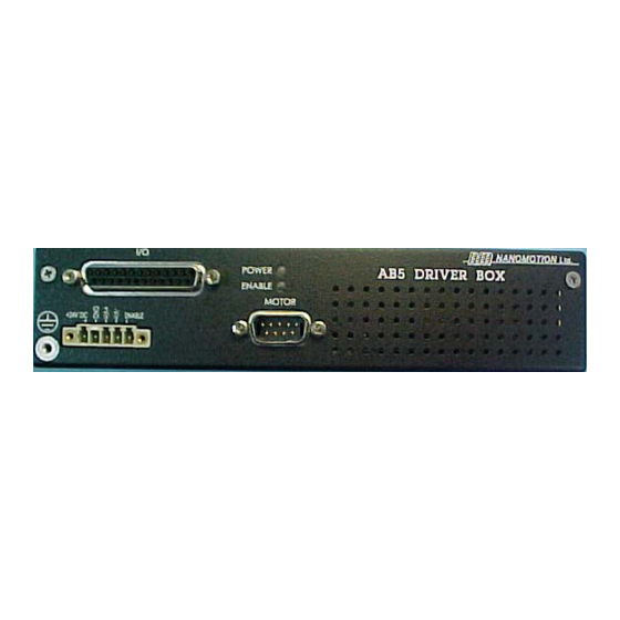
Connections and I/O Settings Connections and I/O Settings Front Panel Description The AB5 front panel (see Figure 1) contains the following connectors and indicators: Control Terminal Motor Output Port I/O Port Power/Enable Indicators Ground Screw Figure 1: AB5 Driver Front Panel... -
Page 10: Front Panel Connectors
Green Motion Control Interfaces The AB5 Driver Box can receive the input signals either from a motion controller or from a joystick. The schematic diagrams of the motion controllers and joystick connections to the AB5 Driver Box are provided in following sections. -
Page 11: Figure 2: Differential Analog Input Connection
Connections and I/O Settings Terminal Block 5 Pin +24V DC Power Supply Twisted and shielded cable Controller D-Type 25 Pin +Vout Vin + -Vout 14 Vin - Shield Status Fault Enable 24 Enable 2 Gnd D-Type 9 Pin Motor 4 Com 5 Down 1 Gnd 6 Motor_Cnctcd... -
Page 12: Figure 3: Non-Differential (Single-Ended) Analog Input Connection
Connections and I/O Settings Terminal Block 5 Pin 1 +24V DC Power Supply 2 Gnd Twisted and shielded cable Controller D-Type 25 Pin +Vout 1 +Vin 14 -Vin Vout (or Gnd) 9 Gnd Shield 2 Gnd Status 3 Fault Enable 24 Enable D-Type 9 Pin Motor... -
Page 13: Joystick Connection
Connections and I/O Settings 2.2.2 Joystick Connection Using the joystick for supplying the command voltage to the AB5 Driver Box allows the user to manually drive the motor without using a motion controller. Terminal Block 5 Pin 1 +24V DC Power Supply... -
Page 14: Cable Connections
If more than one motor is connected to the AB5, use a suitable branch cable. If the motor type or the number of motor elements is changed, consult Nanomotion for the appropriate driver configuration changes that may be required. -
Page 15: Motor Cable Length
2.4.1 Motor Cable Length The maximum allowed total cable length connecting the AB5 to the motor(s) is 20 meters for the HR types and 10 meters for the ST. Minimum length is 0.5m. Use Nanomotion standard cables. Branching is possible to two and four identical motors. -
Page 16: Voltage Source Configuration
The input to be activated should be shorted to external voltage supply ground. Configure jumper JP2 on the top AB5 card according to the voltage source: Pin 1 shorted to Pin 2, for an internal +3.3V source (default factory setting) Pin 3 shorted to Pin 4, for an external +3.3V voltage source... -
Page 17: Fault Output
(see section 2.5.1) • Mechanical screws lock all connectors • The external power supply is capable of supplying the required power consumption of the AB5 (see Table 2) • There is no command when switching the power to “ON” • All motors are correctly mounted. -
Page 18: Ab5 Operation
Both Enable_In and Motor_Connected inputs must be active for operation, regardless of the operation mode. The AB5 can be operated in one of the three operation modes listed below. Velocity (AC) Mode, in which the motor is driven continuously. Step Mode, in which the driver output is turned OFF and ON at hardware, predefined intervals, thus driving the motor in discrete steps. -
Page 19: Velocity Mode Operation
AB5 Operation 3.2.1 Velocity Mode Operation In this operation mode, the motor is driven continuously by applying the analog command voltage (± 10 V) using a relevant interface device (joystick or motion controller). This is the driver default. 3.2.2 Step Mode Operation... -
Page 20: Specifications
Specifications Specifications Parameters and Conditions Table 1: Electrical Specifications Power Input +24 VDC ±5% (stabilized) Power Consumption without Load +24 VDC/200 mA Table 2: Recommended Power Supplies Supply Maximum Current Applicable For Voltage Consumption E1 to E4 +24 VDC ±5% E16. -
Page 21: Ab5 Layout
Specifications AB5 Layout Figure 7: Mechanical Dimensions... -
Page 22: Pin Arrangement
Specifications Pin Arrangement Table 6: Control Terminal Pin Out Signal Name Function Description +24V Input +24 VDC Power Supply Ground +Vin Input Analog Command from controller. -Vin Input Analog Command from controller. Enable_In Input Enable. See section 2.5 Table 7: Motor Output Port Pin Out Signal Name Function Description... -
Page 23: Table 8: I/O Port Pin Out
Specifications Table 8: I/O Port Pin Out Name Function Description V_In_Pos Input 0 to 10VDC Analog control Ground Fault Output See section 2.6 Ground Disabled SPI_Select Disabled Direction Disabled SPI_Data Disabled Acs_Int_Mode Disabled Disabled Set_Com_1 -10V Output -10V supply for external device (Joystick) Emergency_Stop Input Safety shut down See section 2.5... -
Page 24: Envelope Of Performance (Eop) Considerations
Specifications Envelope Of Performance (EOP) Considerations As earlier described (section 1.3), when operating the driver in the Brake Off mode, the motor consumes power at all times, even when the control command voltage is zero, thereby reducing the thermal EOP. Figure 8 on the next page describes the motor velocity-force curves with the allowed operation duty cycle and continued operation. -
Page 25: Figure 8: Eop Considerations
Specifications Break Break Off Break Figure 8: EOP Considerations...
Need help?
Do you have a question about the AB5 and is the answer not in the manual?
Questions and answers