Table of Contents
Advertisement
Quick Links
Advertisement
Table of Contents

Summary of Contents for Phidgets 1063
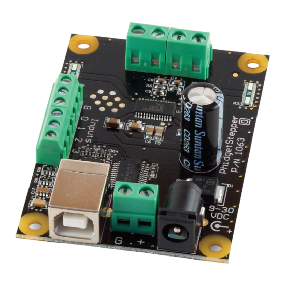
- Page 1 Product Manual 1063 - PhidgetStepper Bipolar 1-Motor...
- Page 2 Phidgets 1063 - Product Manual For Board Revision 0 © Phidgets Inc. 2009...
-
Page 3: Table Of Contents
10 Code Samples 10 API for the PhidgetStepper Bipolar 1-Motor Functions Events 13 Technical Section 13 Introduction to Stepper Motors 13 How does the 1063 control Stepper Motors? 13 How to connect your Stepper to the 1063 Introduction 4 Wire Stepper Motors... - Page 4 Controlling Steppers - Open and Closed Loop Choosing a power supply voltage Figuring out your wattage / power supply current requirements API Variables used to control your motor Continuous Rotation Disabling the PhidgetStepperBipolar Starting the motor High Precision Applications Synchronization of multiple motors 18 Digital Inputs Using the Digital Inputs Functional Block Diagram...
-
Page 5: Product Features
Programming Languages (APIs): VB6, VB.NET, C#.NET, C++, Flash 9, Flex, Java, LabVIEW, Python, Max/MSP, and Cocoa. Examples: Many example applications for all the operating systems and development environments above are available for download at www.phidgets.com >> Programming. Connection The board connects directly to a computer’s USB port. -
Page 6: Getting Started
Make sure that you have the current version of the Phidget library installed on your PC. If you don’t, do the following: Go to www.phidgets.com >> Drivers Download and run Phidget21 Installer (32-bit, or 64-bit, depending on your PC) You should see the icon on the right hand corner of the Task Bar. -
Page 7: Testing Using Mac Os X
0 and the ground connector. The check mark in the Input 0 box should appear. Testing Using Mac OS X • Click on System Preferences >> Phidgets (under Other) to activate the Preference Pane Phidget Bipolar Stepper Controller 1-Motor is properly attached. • Make sure that the Phidget Bipolar Stepper Controller 1-Motor in the Phidget Preference Pane to bring up the •... -
Page 8: If You Are Using Linux
If you are using Linux There are no sample programs written for Linux. Go to www.phidgets.com >> Drivers Download Linux Source • Have a look at the readme file • Build Phidget21 The most popular programming languages in Linux are C/C++ and Java. Notes: Many Linux systems are now built with unsupported third party drivers. It may be necessary to uninstall these drivers for our libraries to work properly. -
Page 9: Programming A Phidget
Programming a Phidget Phidgets’ philosophy is that you do not have to be an electrical engineer in order to do projects that use devices like sensors, motors, motor controllers, and interface boards. All you need to know is how to program. We have developed a complete set of Application Programming Interfaces (API) that are supported for Windows, Mac OS X, and Linux. -
Page 10: Documentation
Functions int MotorCount() [get] Returns the number of motors this PhidgetStepper can control. In the case of the 1063, this will always return 1. This call does not return the number of motors actually connected. double Acceleration(int MotorIndex) [get,set] Acceleration is the maximum change in velocity the PhidgetStepper uses when speeding up or slowing down the motor. This is specified in the same units used for Position - in the case of the 1063, 1/16th steps. - Page 11 VelocityMin is the minimum VelocityLimit the PhidgetStepper can accept. In the case of the 1063, this will always return 0. Functionally, it is the minimum speed that the 1063 can drive your motor at. For very low speeds, you can increment position inside a slow software based timing loop.
-
Page 12: Events
CurrentMin is the smallest CurrentLimit the PhidgetStepper can accept. In the case of the 1063, this will always return 0.0542. int InputCount() [get] Returns the number of Digital Inputs available on this PhidgetStepper. In the case of the 1063, there are 4 Digital Inputs. bool InputState(int InputIndex) [get] Returns the state of a particular Digital Input. -
Page 13: Technical Section
At low speeds, less than 1024 1/16th steps per second, the 1063 uses a microstepping scheme to allow precise control of the current to each coil, and therefore the position of the stepper. It’s important to note that many steppers are not designed to be microstepped precisely, and will not accurately produce the expected angle. -
Page 14: Wire Stepper Motors
By applying current to the two coils in sequence, and changing the direction of current flow, the motor can be made to rotate. Determining how to connect a 4 wire stepper to the 1063 can be done by following this procedure. Start by measuring the resistance between all the wires. Below is a sample table of resistance data, in ohms. -
Page 15: Controlling Steppers - Open And Closed Loop
8 Wire Stepper Motors 8 Wire Motors are very difficult to wire up if you do not have a schematic showing how the wires are connected to the internal coils. Only follow these instructions if you are really desperate. In an 8 wire motor, the coils are split, and we have to reconnect the coils, to reduce them to a 4 wire. -
Page 16: Choosing A Power Supply Voltage
Choosing a power supply voltage The 1063 can operate from 9 to 30 VDC. It is able to reduce the voltage if your motor requires less, but it cannot increase the voltage. First, find the resistance of the coils in your motor. We will assume 4 Ohms. Add 0.5 Ohms to this to account for the electronics on the 1063. Decide the maximum current you want to push through the coils. -
Page 17: Disabling The Phidgetstepperbipolar
Disabling the PhidgetStepperBipolar When the stepper motor has rotated the requested number of steps, and is stopped, the coils will remain energized to hold it in position. This is necessary to allow the motor to support a load on its shaft without rotating to an unknown position. -
Page 18: Digital Inputs
Digital Inputs Using the Digital Inputs Here are some circuit diagrams that illustrate how to connect various devices to the digital inputs on your Phidget. W iring a sw itch to a Digital Input Closing switch causes digital input to report TRUE W iring a sw itch to a Digital Input Closing switch causes digital input to report TRUE USER... - Page 19 Current through LED causes Digital Input to report TRUE Input Drain-Source Current > 270uA causes Digital Input to report TRUE Drain-Source Current < 67uA guarantees Digital Input to report TRUE INPUT Isolating a Digital Input with an Optocoupler USER Phidget When driving current through the LED, the Digital Input will APPLICATION Digital...
-
Page 20: Functional Block Diagram
Collector-Emitter Current > 270uA causes Digital Input to report TRUE FSR Resistance rising above 75k Ohms causes Digital Input Collector-Emitter Current < 67uA guarantees Digital Input to report FALSE This design can be used w ith any variable resistance sensor USER Phidget USER... -
Page 21: Device Specifications
Date Board Revision Device Version Comment January 2009 Product Release Support Call the support desk at 1.403.282.7335 9:00 AM to 5:00 PM Mountain Time (US & Canada) - GMT-07:00 E-mail us at: support@phidgets.com 1063_0_Product_Manual - October 27, 2010 2:54 PM...
Need help?
Do you have a question about the 1063 and is the answer not in the manual?
Questions and answers