Table of Contents
Advertisement
KEEP THIS MANUAL IN A SAFE PLACE FOR FUTURE REFERENCE!
Read this manual before using this product. Failure to follow the instructions and safety precautions in this manual can result in
PART NUMBER
04004999-MB
04004999-SB
For a list of relevant patents and trademarks, please see http://www.chentronics.com/legal-notices.
MNL-ISCAN3, REVB
DCO #12743
serious injury or death or damage to equipment.
Applicable Scanner Part Numbers
MODEL
AREA CLASSIFICATION
iS3-MB
CLASS I/DIVISION II
iS3-SB
CLASS I/DIVISION II
Contact Technical Support +1.866.821.5504 with any questions.
INSTALLATION & OPERATION MANUAL
For Technical Support Call: +1.866.821.5504
TEMP RATING
Fully Programmable – Must Be
-40°C to 80°C
Configured Prior to Use
-40°C to 80°C
Limited Programmability
FEATURE
CONNECTOR PINS
Page 1 of 25
Schedule Document
16
16
Advertisement
Table of Contents

Related Manuals for Chentronics iScan3 Series

Summary of Contents for Chentronics iScan3 Series
- Page 1 CLASS I/DIVISION II -40°C to 80°C Limited Programmability Contact Technical Support +1.866.821.5504 with any questions. For a list of relevant patents and trademarks, please see http://www.chentronics.com/legal-notices. MNL-ISCAN3, REVB INSTALLATION & OPERATION MANUAL Page 1 of 25 DCO #12743 For Technical Support Call: +1.866.821.5504...
-
Page 2: Table Of Contents
Contents IMPORTANT SAFETY INFORMATION ..............................3 CUSTOMER SUPPORT ..................................5 PRODUCT FEATURES ..................................6 ....................................6 ASE OF NSTALLATION ....................................8 HERMAL ROTECTION TECHNICAL SPECIFICATIONS ................................9 ......................................9 EFINITIONS ....................................10 PECIFICATION ABLE Technical Specification NOTES ................................ 11 ) ................................12 EFAULT ONFIGURATION ETTINGS... -
Page 3: Important Safety Information
IMPORTANT SAFETY INFORMATION Read All Instructions before Using Equipment The instructions provided in this manual have been prepared to serve as a general guide. It is intended for use by qualified personnel with knowledge of equipment of this type. It is not intended to cover all possible variations in equipment or to provide for specific operating problems which may arise. - Page 4 EXPLOSION HAZARD Do not open the equipment cover or service the equipment if an explosive atmosphere may be present. Equipment must be installed and serviced by qualified personnel in accordance with applicable local and national codes, standards, and ordinances. Lisez toutes les instructions avant d'utiliser l'équipement Les instructions fournies dans ce manuel ont été...
-
Page 5: Customer Support
L'équipement doit être installé et entretenu par du personnel qualifié conformément aux codes, normes et ordonnances locales et nationales applicables Customer Support For Technical Support Inside USA Call: 866.821.5504 Outside USA Call: +1.607.334.5531 Website: www.chentronics.com MNL-ISCAN3, REVB INSTALLATION & OPERATION MANUAL Page 5 of 25 DCO #12743 For Technical Support Call: +1.866.821.5504... -
Page 6: Product Features
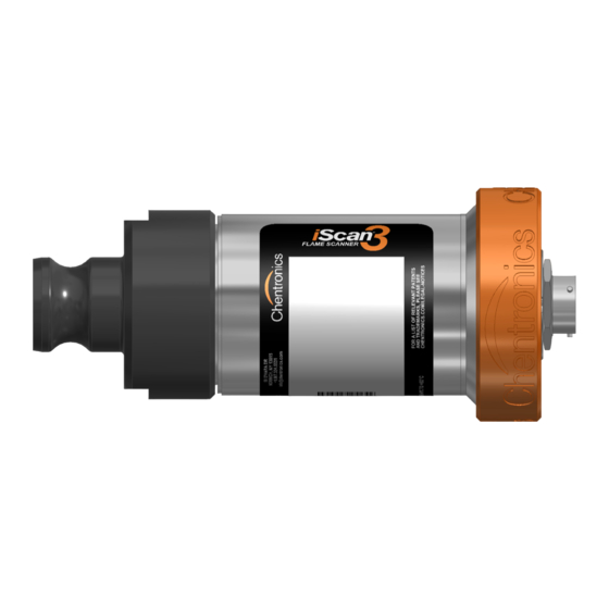
Product Features The iScan3 flame scanner is designed to detect flame from fossil fuels such as natural gas, refinery gas, waste gas, fuel oils, biomass and coals. The iScan3 consists of an integrated viewing head and signal processor. No secondary signal processor or amplifier is required. - Page 7 LED STATUS INDICATORS; “Ring of Light”: The iScan3 is equipped with a highly visible LED status indicator ring. This “Ring of Light” communicates the scanner’s operating modes including FLAME SIGNAL STRENGTH, GAIN LEVEL (the amount of signal amplification), and WARNINGS/FAULTS. This ring aids with “sighting” the flame; or in other words: proper aiming of the scanner. This must be done with care to ensure that a good flame signal is present over a range of operating conditions.
-
Page 8: Thermal Protection
Thermal Protection The iScan3 Flame Scanner has redundant safety features for exposure above the maximum temperature rating. The modes of operation are described below: Mode Internal Temperature (T 4-20 Output Setting Indicator Light Setting Relay Operation Normal ≤ 95°C Normal (4-20 mA) Normal Normal Alternate left half yellow 0.5s... -
Page 9: Technical Specifications
Technical Specifications Definitions FLICKER – Flicker or Flicker Frequency refers to the modulation of flame intensity due to micro-explosions. FDORT – Flame Detector ON Response Time – the period of time from flame intensity rising above the user adjustable threshold to flame relay contacts closed. FDRT –... -
Page 10: Specification Table
Specification Table AREA CLASSIFICATION Hazardous/Non-Hazardous Area Part Number PN 04004999-SB, 04004999-MB Area Classification Input Cable Quick Disconnect - Separate Cable Weight 2.25 lb. (1.02 kg) Mounting 1” NPT(F) Purge Air NOTE 1 Flow 5 scfm (8.5 Nm /hr) Pressure 5” w.c. (13 mbar) ROL - Ring of Light Status Color Coded Status Indicator... -
Page 11: Technical Specification Notes
AREA CLASSIFICATION Hazardous/Non-Hazardous Area Part Number PN 04004999-SB, 04004999-MB Safety Integrity Level (SIL3) PFDavg = 938.369 X 10 Data λS = 1.14 X 10 λDD = 2.1705 X 10 λDU = 0.0219 X 10 SFF = 99.1% Proof Test Interval time = 1 year (8760 Hrs) NOTE 6 Technical Specification NOTES... -
Page 12: Default Configuration (Settings)
Default Configuration (Settings) As part of setup in iScanSoftware, each scanner is assigned unique addresses. Flame Detector On Response Time (FDORT) 2 seconds nominal Flame Detector Response Time (FDRT) 1 second nominal Marginal Flame Failure Response Time (MFFRT) 2 seconds nominal Gain Configuration Manual Gain Channel... -
Page 13: Wiring Instructions
Wiring Instructions All wiring shall be done in accordance with all applicable local and national codes, standards, and ordinances. The scanner has a quick connect cable. This cable does not require a flexible conduit if permitted by local authority. Connections for power, Earth Ground, and Flame Relay (N.O. and Common) are required for all applications. Use of the 4-20 mA outputs, Communications, and connections are “as-required”... - Page 14 Note 5 Connect the scanner Earth GND (Green/Yellow, 8, <H>) to EARTH GROUND. A short BRAIDED CONDUCTOR (alternately a short AWG #12 wire) is recommended. Note 6 All shields are tied to Earth Ground in the Control Panel only. ALL OTHER CONNECTIONS GREEN/YELLOW (8) <H>...
- Page 15 • Les interférences électriques provenant de sources d'allumage haute tension / énergie peuvent nuire au bon fonctionnement du scanner à flamme. Pour minimiser les risques d'interférences électriques avec le fonctionnement du scanner à flamme: • Ne pas installer les câbles d'allumage dans le même conduit que les câbles du scanner •...
-
Page 16: Cable Connection
Cable Connection Scanner Power/Control Cable Installation The iScan3 system utilizes a quick disconnect connector to connect the power/control cable to the electronics. To connect the power cable to the electronics, first turn the locking nut clockwise by hand until it is seated against the electronics. - Page 17 B: S IGURE EAT THE CONNECTOR AND SEAT THE LOCKNUT AGAINST THE CONNECTOR BARREL C: T IGURE IGHTEN LOCKING NUT AGAINST CONNECTOR BARREL EXPLOSION HAZARD DO NOT CONNECT OR DISCONNECT WHEN ENERGIZED TENSION DANGEREUSE NE PAS CONNECTER OU DÉBRANCHER LORSQUE ÉNERGÉ MNL-ISCAN3, REVB INSTALLATION &...
-
Page 18: Communications Wiring
Communications Wiring RS-485 Communication with the iScan3 is RS-485 via a USB to RS-485 Converter (PN 3425-057-01). RS-485 is a differential multi-drop network. For iScan3, the network is a half-duplex, 2-wire, echo-off configuration operating at 19200 KBAUD. The maximum allowable number of nodes on a given section of the network is 32 including the USB to RS-485 converter and any repeaters. If more than 32 loads are connected (1 USB converter, 1 RS-485 repeater and 30 iScan3s) then an RS-485 repeater is required between sections to boost the signal. -
Page 19: "Daisy Chain" Configuration
“Daisy Chain” Configuration MNL-ISCAN3, REVB INSTALLATION & OPERATION MANUAL Page 19 of 25 DCO #12743 For Technical Support Call: +1.866.821.5504 Schedule Document... -
Page 20: Split Or "Y" Configuration
Split or “Y” Configuration MNL-ISCAN3, REVB INSTALLATION & OPERATION MANUAL Page 20 of 25 DCO #12743 For Technical Support Call: +1.866.821.5504 Schedule Document... -
Page 21: Remote File Select
Remote File Select The Remote File Select feature provides a means for automatically selecting one the configuration files resident within the scanner. iScan3 has a two wire or four wire option to remotely select files. File select configurations are wire fault protected; meaning if any wire combination is broken, i.e. -
Page 22: Sighting The Scanner
Sighting the Scanner EXPLOSION HAZARD This Failure to sight the scanner properly can cause an explosion. Equipment must be installed and serviced by qualified personnel in accordance with applicable local and national codes, standards, and ordinances. TENSION DANGEREUSE N'ouvrez pas le capot de l'équipement et ne le réparez pas si une atmosphère explosive peut être présente. -
Page 23: Ring Of Light Scanner Status Display
Ring of Light Scanner Status Display Move the scanner while observing the LEDs on the back of the scanner. The left LEDs will turn red and light up just 1 bar [A6] when no flame is detected, when running under auto gain mode, the right LEDs will show purple color and the bar number will increase until it reaches to half ring. -
Page 24: Maintenance
Maintenance The scanner is a rugged, high temperature device, and contains no moving parts. NEVER open the scanner housing. Doing so may damage the scanner and will void the warranty. N'ouvrez JAMAIS le boîtier du scanner. Cela pourrait endommager le scanner et annuler la garantie Cleaning the Lens The only maintenance that may be required is periodic cleaning of the outside of the quartz glass lens. -
Page 25: Special, "X", Conditions Of Use
Ne retirez pas l’objectif du boîtier du scanner. Cela pourrait endommager le scanner et annuler la garantie Special, “X”, Conditions of Use • The equipment should only be used in an area that has low risk of impact. • The equipment should be used in area that is free from falling debris. •...
Need help?
Do you have a question about the iScan3 Series and is the answer not in the manual?
Questions and answers