
Summary of Contents for US Water Systems Defender 223-DFROM Series
- Page 1 Visit us online at www.uswatersystems.com Owners Manual Models 223-DFROM –XXXX US Water Systems Corporate Office 1209 Country Club Road Indianapolis, IN 46234 REVISION # 1-800-608-8792 REVISION DATE: June 25, 2019...
-
Page 2: Table Of Contents
Be sure to check the entire RO system for any shipping damage or parts loss. Also note damage to the shipping cartons. Contact US Water Systems at 1-800-608-8792 to report any shipping damage within 24 hours of delivery. Claims made after 24 hours may not be honored. -
Page 3: Proper Installation
Proper Installation This RO system must be properly installed and located in accordance with the Installation Instructions before it is used or the warranty will be void. Do not install or store where it will be ex- posed to temperatures below freezing or ex- 32°... -
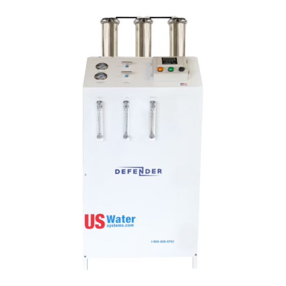
Page 4: Component Identification
Component Identification 1. Solenoid Valve - Turns ON/OFF Feed Water Supply when the tank input circuit is opened 2. 5 Micron Sediment Pre-filter - Removes Sediment from the Feed Water 3. Filter IN Pressure Gauge - Monitors Feed Water Pressure prior to the Pre-filters 4. - Page 5 Component Identification 5. Computer Control - The Minitrol Controls ON/OFF Function as well as Fail Safe Switches. 6. Recycle/Recirculation Valve - Controls the amount of Concentrate Water that is Fed back to the Mem- branes for Recycle 7. Concentrate/Waste Valve - Controls the amount of Concentrate Water going to the drain for waste. 8.
- Page 6 Component Identification 9. Throttle Valve - Adjusts the Boost Pressure to the Membranes. WARNING! Do not exceed 150psi. 10. Permeate/Product Flow Meter - Monitors the amount of Permeate Water going to the storage or distribution system. 11. Concentrate Flow Meter - Monitors the amount of Concentrate Water going to drain. 12.
- Page 7 Component Identification 13. Low Pressure Switch - Shuts the system down as a fail safe in a Low Feed Water Pressure condition. This pressure switch is in the RO controller. 14. Membrane Pressure Vessels - Holds the Membranes 15. Power Supply Cord 16.
-
Page 8: Specifications
DFROM-2000 Specifications Design Vessels Configuration Single Pass Vessel Array Feed Water Source City or Well Water Vessel Quantity Standard Recovery Rate Recovery with Concentrate Recycle Up to 75% Rejection and Flow Rates Pumps Nominal Salt Rejection % 98.5 Pump Type Multi-Stage Permeate Flow* gpm (lpm) 1.38 (5.22) - Page 9 DFROM-4000 Specifications Design Vessels Configuration Single Pass Vessel Array Feed Water Source City or Well Water Vessel Quantity Standard Recovery Rate Recovery with Concentrate Recycle Up to 75% Rejection and Flow Rates Pumps Nominal Salt Rejection % 98.5 Pump Type Multi-Stage Permeate Flow* gpm (lpm) 2.78 (10.52)
- Page 10 DFROM-6000 Specifications Design Vessels Configuration Single Pass Vessel Array 1:1:1 Feed Water Source City or Well Water Vessel Quantity Standard Recovery Rate Recovery with Concentrate Recycle Up to 75% Rejection and Flow Rates Pumps Nominal Salt Rejection % 98.5 Pump Type Multi-Stage Permeate Flow* gpm (lpm) 4.16 (15.80)
- Page 11 DFROM-8000 Specifications Design Vessels Configuration Single Pass Vessel Array 1:1:1:1 Feed Water Source City or Well Water Vessel Quantity Standard Recovery Rate Recovery with Concentrate Recycle Up to 75% Rejection and Flow Rates Pumps Nominal Salt Rejection % 98.5 Pump Type Multi-Stage Permeate Flow* gpm (lpm) 5.56 (21.13)
- Page 12 DFROM-12,000 Specifications Design Vessels Configuration Single Pass Vessel Array 2:2:2 Feed Water Source City or Well Water Vessel Quantity Standard Recovery Rate Recovery with Concentrate Recycle Up to 75% Rejection and Flow Rates Pumps Nominal Salt Rejection % 98.5 Pump Type Multi-Stage Permeate Flow* gpm (lpm) 8.33 (31.67)
-
Page 13: Rejection, Recovery & Flow Rates
Rejection, Recovery & Flow Rates The US Water Systems DEFENDER reverse osmosis systems are designed to produce permeate water at the capacities indicated by the suffix in the system’s name under the conditions listed above. For example, the DE- FENDER-4000 produces 4000 gallons per day of permeate water at the listed operating test conditions. -
Page 14: Electrical Connections
System Connections, Requirements and Guidelines PERMEATE (PRODUCT WATER) CONNECTION 1. Locate the 1/2” tubing labeled permeate and attach to the bulkhead in the top of the storage tank. Ensure that the permeate water can flow freely with no backpressure. Backpressure can cause irreversible damage to the membrane elements. -
Page 15: Pre-Filtration, Pump & Membranes
A water test of the feed water is used to determine the proper pretreatment equipment. Contact US Water Systems for help determining what pre- treatment equipment is required. 1-800-608-8792. -
Page 17: Tank Level & Pre-Treatment Lockout Wiring
Tank Level and Pre-treatment Lockout Wiring The DEFENDER systems are equipped with a switch closure circuit that control the RO system ON/OFF. This is a “no voltage” switch closure circuit (dry contact). Tank Level Input There is a switch closure circuit used to turn some RO systems on and off when an atmospheric tank float is installed. -
Page 18: Anti-Scalant Filling And Settings
Remove the cover on the Tank Connection access elbow. Screw the strain relief on the float wire into the access elbow. Connect the Black and Blue wire to each of the Green wires on the RO. Tighten the strain relief and install the cover. NOTE: If Pretreatment Lockout is utilized, a different wire routing method may be required. -
Page 19: Glossary Of Terms
3. Make sure the toggle switch on the injection pump is in the “ON’ position. US Water Hyper-Guard Plus 7000 Anti-Scalant Mixture RO GPD Rating Initial Fill for Entire 15 Gallon Tank Ongoing Fill Per Gallon of Refill RO Water 2,000 13.5oz 0.9oz... -
Page 20: Ro Start-Up
RO Start-up Adjusting the RO System Flow Rates Be sure the pre-treatment systems have been flushed and put in service. If anti-scalant is being used, be sure to confirm the dose and mix of the solution with the sales rep before starting the system. If possible remove the prefilter and fill it with water. -
Page 21: Operating Do's And Don'ts
RO Start-up 75% Recovery System Adjustment Turn the concentrate valve clockwise until the permeate flow rate and the concentrate flow rate are at designed standards. Turn the recycle valve until the recycle flow rate is at the desired rate. If necessary, adjust the pump throttle valve, concentrate valve and concentrate recycle valve until the proper flow rates are achieved. -
Page 22: Low Pressure Switch, Pump Throttle Valve & Adjustment Of Throttle Valve
Low Pressure Switch The low pressure switch shuts off the system when the feed water pressure drops below 15 PSI, preventing damage to the pump. The system restarts automatically when there is a constant pressure of 30 PSI or more. NOTE: If you notice the pressure fluctuating, and the system cycling off and on, turn the system off and ensure that proper feed flow and pressure are available to the system. -
Page 23: Membrane Removal And Replacement
Membrane Removal & Replacement Replacing membranes in the pressure vessels is an easy process if you have the proper information and tools at hand. Please refer to the following instructions when removing and replacing membrane elements: WARNING: ALL PRESSURE GAUGES MUST READ ZERO BEFORE PROCEEDING. BEFORE ATTEMPTING, DISCONNECT THE POWER FROM THE SYSTEM AND BLEED ALL WATER PRESSURE FROM THE SYSTEM! Remove the end caps from the top of the membrane housings... -
Page 24: Flushing The System
Flushing the System The system should be flushed weekly to remove sediment from the surface of the membranes. To manually flush the system follow the preceding steps: The system must be operating during the flush procedure Fully open the concentrate valve. Allow the system to run for 10 to 20 minutes After 10 to 20 minutes, close the concentrate valve to its previous setting. -
Page 25: Temperature Correction Factors For Membranes
Temperature Correction Factors For Membranes Find the temperature correction factor (TCF) from the table below. Divide the rated permeate flow at 77 F by the temperature correction factor. The result is the permeate flow at the desired temperature. If a system is rated to produce 5 gpm of permeate water @ 77˚ F. The same system will produce more water at a higher temperature. -
Page 26: Flow Diagrams
DEFENDER Flow Diagram... - Page 27 DEFENDER Flow Diagram...
-
Page 28: Typical Layout Drawing
Typical System Layout Drawing... -
Page 29: Controller Programming Instructions
Controller Programming Options... - Page 30 Controller Programming Options...
- Page 31 Controller Programming Options...
-
Page 32: Electrical Schematic
DEFENDER Electrical Schematic... -
Page 33: Warranty
Purchaser must use Genuine US Water Filters, Membranes, UV Parts and Anti-Scalant in order for Warranty to be valid. US Water Systems assumes no responsibility for subsequent or consequential damages, labor or expense incurred as a result of a defect or for failure to meet the terms of these guarantees because of circumstances beyond our control. Installation workmanship failure is not covered under warranty.
Need help?
Do you have a question about the Defender 223-DFROM Series and is the answer not in the manual?
Questions and answers