Advertisement
Quick Links
Advertisement

Related Manuals for Orangepip Segments328

Summary of Contents for Orangepip Segments328
- Page 1 Build Instructions...
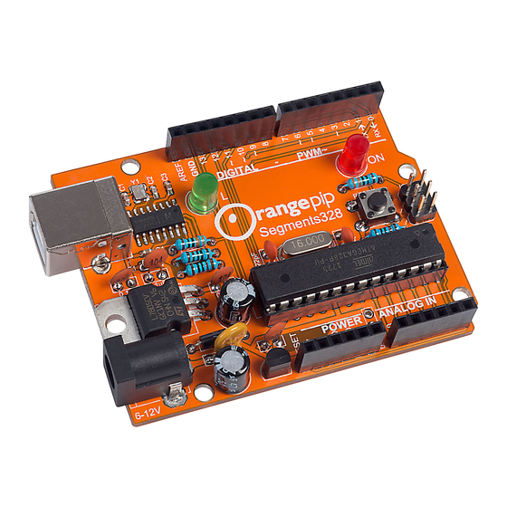
- Page 2 Check contents before you build! Orangepip Segments PCB 16MHz crystal ATmega328 Microcontroller Dual in line socket Tactile switch Red LED Green LED 6-pin dual row header 8-pin single row sockets 6-pin single row sockets USB socket Power supply jack socket...
- Page 3 How to build your … Orangepip Segments328 To put your Orangepip Segments328 together you will need basic soldering skills. When soldering you should always work on a flat surface in a well-ventilated environment. Make sure you have plenty of room on your workspace.
- Page 4 Locate the bag containing the resistors. This will include 5 pieces in total. Sort them carefully into their respective values using the illustrations below. There are three ways to identify the value of a resistor: Using a Multimeter 330R x 2 pieces. Orange, Orange, Black, Black, Brown •...
- Page 5 Locate the crystal and place into the board. Use the leg bending tip from earlier to keep the crystal flush to the PCB and solder in place. Locate the bag containing the microcontroller and the DIL socket. The chip carrier socket is not polarity sensitive, but you will notice that there is a notch in one end. This is used to assist with the correct placement of the Microcontroller, which is polarity sensitive.
- Page 6 Separate the ceramic capacitors from the other components. The 0.1uF capacitors are marked with the number 104 and the 22pF are marked with the number 22. 0.1uF 22pF Place the 0.1uF (104) capacitors into the marked locations on the PCB and solder in place.
- Page 7 Locate the 7133 regulator. This regulator is polarity sensitive and needs to be inserted into the PCB the correct way round. The marking on the PCB is shaped to match the component. The flat face of the regulator should be facing away from the Orangepip logo towards the edge of the board.
- Page 8 2.10 Locate the PTC resettable fuse. This component is not polarity sensitive so place into the PCB and solder in place. 2.11 Locate the 47uF electrolytic capacitors. These are polarity sensitive, so you need to ensure they are mounted the correct way round. To assist with this the capacitors have two indicators to help identify the orientation.
- Page 9 Locate the ICSP 6 pin header. This is not polarity sensitive, but you will notice that the legs either side of the black plastic are different lengths. The shorter ends should be on the underside of the boards with the longer ends accessible from the top. Locate the green and red LEDs.
- Page 10 Locate the 2.1mm DC socket. Insert it into the PCB and solder in place. The last job is to insert the ATmega328 microcontroller into the chip carrier socket you soldered earlier. The microcontroller is polarity sensitive. Find the end that has the notch and line this up with the notch on the microcontroller.
Need help?
Do you have a question about the Segments328 and is the answer not in the manual?
Questions and answers