
Related Manuals for Kostrzewa Platinum Bio ecoMAX860P3-O TOUCH (VG)


Summary of Contents for Kostrzewa Platinum Bio ecoMAX860P3-O TOUCH (VG)
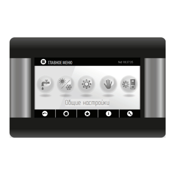
- Page 1 Лидер среди пеллетных котлов ГЛАВНОЕ МЕНЮ Общие настройки Platinum Bio ecoMAX860P3-O TOUCH (VG) ИНСТРУКЦИЯ ПО ЭКСПЛУАТАЦИИ USER MANUAL...
- Page 3 ИНСТРУКЦИЯ ПО ЭКСПЛУАТАЦИИ USER MANUAL...
- Page 5 Лидер среди пеллетных котлов ГЛАВНОЕ МЕНЮ Общие настройки Регулятор Platinum Bio ecoMAX860P3-O TOUCH (VG)
- Page 7 Фирма КОСТШЕВА...
- Page 10 ...
- Page 16 ...
- Page 17 ...
- Page 18 ...
- Page 22 ГЛАВНОЕ МЕНЮ Служебные настройки Platinum Bio ecoMAX860P3-OTOUCH (VG) Инструкция ПО ОБСЛУЖИВАНИЮ...
- Page 23 Гидравлические схемы...
- Page 24 Гидравлические схемы ГВ С...
- Page 25 Гидравлические схемы...
- Page 26 Гидравлические схемы...
- Page 28 ...
- Page 29 ...
- Page 34 погодный...
- Page 36 ...
- Page 37 Сервисное меню...
- Page 38 Сервисное меню...
- Page 39 Сервисные настройки Настройки горелки...
- Page 40 Сервисные настройки ...
- Page 41 Сервисные настройки Настройки ГВС и ц о...
- Page 42 Сервисные настройки Настройки буфера Настройки смесителя...
- Page 43 Сервисные настройки ...
- Page 46 Настройки буфера...
- Page 47 Настройки ГВС...
- Page 49 Leader in pellet boilers Platinum Bio ecoMAX860P3-O TOUCH (VG) controller User Manual...
- Page 50 Platinum Bio ecoMAX 860P User Manual – EN 03.17 Leader in pellet boilers...
- Page 51 Please read this User manual before connecting and operating the controller to ensure safe and failure-free operation of the device. We would like to thank you for choosing KOSTRZEWA equipment, top quality device manufactured by a Before installation and commissioning: renowned and highly valued company, both in Poland and Check if the device components were not damaged during transport.
- Page 52 Platinum Bio ecoMAX 860P User Manual – EN 03.17 Leader in pellet boilers...
-
Page 53: Table Of Contents
Contents Platinum Bio ecoMAX 860P controller User Manual Safety guidelines General Manual information Storing documents Symbols and designations WEEE Directive 2002/96/WE User menu Operation Alarm description Platinum Bio ecoMAX 860P controller Service manual Hydraulic diagrams Specifications Storage and transport conditions Installing controller Service menu Service settings... -
Page 54: Platinum Bio Ecomax 860P Controller User Manual
1. Safety... | 2. General...| 3. Manual...| 4. Storing...| 5. Symbols...| 6. WEEE... 3. Manual information 1. Safety guidelines This User Manual is part of the boiler documentation. Please follow instructions Safety requirements are detailed in further sections of this User Manual. Please provided in the boiler documentation. -
Page 55: User Menu
7. User menu 7. User menu Main menu Boiler settings Information Boiler temperature setpoint Boiler settings Boiler outdoor temperature compensation* DHW settings* Boiler heating curve* Summer/Winter Curve translation* Mixing valve 1-5 settings* Room temperature coefficient* General settings Power modulation at grate* Manual control ·... - Page 56 7. User menu DHW settings General settings DHW temperature setpoint Clock DHW pump operation mode Date DHW storage tank hysteresis Screen brightness DHW disinfection Sound DHW storage tank nighttime setback Language Circulation pump nighttime setback* Software update WiFi settings* * not available if no sensor or additional module is installed or the parameter is hidden.
-
Page 57: Operation
8. Operation 8. Operation 8.1 Main screen values affecting temperature setpoint: operation modes: STARTUP, OPERATION, MONITORING, CLEANING, room thermostat contacts open - room temperature SHUTDOWN, STAND-BY, GRATE setpoint not reached. boiler temperature setpoint - hold to edit value measured boiler temperature temperature setpoint decreased by active intervals. - Page 58 8. Operation 8.2 Boiler startup and shutdown Make sure the fuel is available, the boiler door is closed, and touch the screen (Boiler OFF); the following message is displayed: Turn the controller on? czas podawania przerwa podawania czas podawania przerwa podawania ecoMAX860P3-O TOUCH (VG) praca praca...
- Page 59 8. Operation 8.9 Cleaning settings Burner cleaning settings can be modified in: Boiler settings > Cleaning IF DHW STORAGE TANK IS HEATED ONLY (SUMMER MODE), IT IS Continuous burner operation time, after which it is automatically shut down, RECOMMENDED TO SWITCH THE CONTROLLER TO STANDARD MODE. cleaned and started again is set in Burner cleaning and Service settings >...
- Page 60 8. Operation 8.12 STAND-BY mode In STAND-BY mode, the burner is shutdown and awaits start signal e.g. • boiler temperature setpoint decrease below temperature setpoint minus AT LOW HYSTERESIS SETTING, DHW PUMP WILL ACTIVATE boiler hysteresis value, QUICKER AFTER THE DHW TEMPERATURE DECREASES. •...
- Page 61 8. Operation • Setting the mixing valve with weather compensator, without room temperature controller. Set Mixing valve outdoor temperature compen- sation to ON. Select the outdoor temperature compensation curve as per 8.20. With Curve translation, set room temperature setpoint, using the following equation: Room temperature setpoint = 20°C + heating curve translation.
- Page 62 8. Operation Use Decrease value to set decrease in temperature for all time intervals. The • Operation: The controller determines fuel level based on its consumption. nighttime setback can be defined individually for every day of the week in The factory settings will not always reflect the actual fuel consumption, Schedule.
-
Page 63: Alarm Description
8. Operation | 9. Alarm description 8.32 Operation with internet module 8.25 Selecting heat source The controller is compatible with ecoNET300 internet module. The controller allows to select a single main heat source which supplies the The module allows on-line operation of the controller via Wi-Fi or LAN through a heating circuits. - Page 64 9. Alarm description 9.9 Communication error Control panel is connected to the electronics via a digital communication link RS485. If cable is damaged, „Caution! No communication” alarm is displayed. POPERATION IN THE EMERGENCY MODE IS ALLOWED UNDER The controller continues operation with programmed parameters. Check, USER SUPERVISION UNTIL THE FAULT IS REMOVED BY THE SERVICE replace or repair the cable connecting the control panel to the module.
-
Page 65: Platinum Bio Ecomax 860P Controller Service Manual
Leader in pellet boilers Platinum Bio ecoMAX860P3-O TOUCH (VG) controller SERVICE manual... -
Page 66: Hydraulic Diagrams
10. Hydraulic diagrams 10. Hydraulic diagrams The following diagrams do not replace central heating and domestic hot water system design and are for information only. Diagram with four-way valve controlling the central heating circuit: boiler with control panel; controller module; SET HIGH BOILER TEMPERATURE SETPOINT FOR THE VALVE (6) CT4 boiler return water temperature sensor;... - Page 67 10. Hydraulic diagrams Recommended settings: Parameter Setpoint MENU Boiler temperature setpoint 70-80°C menu > boiler settings Boiler temperature increase 5-20°C menu > service settings > CH and DHW settings Mixing valve 1 control CH enabled menu > service settings > mixing valve 1 settings Max.
- Page 68 10. Hydraulic diagrams Recommended settings: Parameter Setpoint MENU Central heating pump start temperature 55°C menu > service settings > CH and DHW settings Mixing valve 1 control CH enabled menu > service settings > mixing valve 1 settings Max. mixing valve 1 temperature 70°C menu >...
- Page 69 10. Hydraulic diagrams Recommended settings: Parameter Setpoint MENU Boiler temperature setpoint 80°C menu > boiler settings Central heating pump start temperature 55°C menu > service settings > CH and DHW settings Buffer tank control Enabled menu > service settings > buffer tank settings Buffer tank charging start temperature 50°C menu >...
-
Page 70: Specifications
11. Specifications | 12. Storage and transport... | 13. Installing controller 11. Specifications 13. Installing controller Specifications 13.1 Environmental conditions Due to the fire hazard do not use the controller in the atmosphere of explosive Power supply 230V~; 50Hz; gases and liquids. Do not use the controller in places exposed to condensation Controller power input 0,04 A or water. - Page 71 13. Installing controller Panel mounting conditions: panel, vents for air circulation (note: vents must not reduce protection rating; vents are not required if ambient temperature is not exceeded). • Panel removal: Insert flat bars (2) into the slots to remove the panel (1) from its enclosure.
- Page 72 13. Installing controller Module mounting: a - in a modular enclosure with front panel access, b - in an enclosure without front panel access, 1 - main module, 2 - DIN TS35 rail, 3 - catch. 13.5 IP protection rating Main module enclosure provides different protection ratings depending on the CONNECTION CABLES MUST NOT CONTACT ANY SURFACES WITH mounting method used.
- Page 73 13. Installing controller Wiring diagram MB10kW-v03-T4: burner PB VG + ecoMAX 860 P3 module variant O + module B FEMALE CONNECTOR GREEN Platinum Bio ecoMAX 860P User Manual – EN 03.17 Leader in pellet boilers...
- Page 74 13. Installing controller Wiring diagram for ecoMAX860P3-O TOUCH (VG) controller: Platinum Bio ecoMAX 860P User Manual – EN 03.17 Leader in pellet boilers...
- Page 75 13. Installing controller Wiring diagram – auxiliary module B to ecoMAX860P3-O TOUCH (VG) controller: Platinum Bio ecoMAX 860P User Manual – EN 03.17 Leader in pellet boilers...
- Page 76 13. Installing controller ecoMAX 860P3- v. O control module outputs and ecoMAX 800 P2- module B extension module outputs Module A Module B STB - safety temperature limiter STB MC - CH sensor - circuit C EF - storage bin feeder MD - CH sensor - circuit D CF - burner fan BH - buffer tank top temperature sensor...
- Page 77 13. Installing controller 13.8 Connecting temperature sensors 13.10 Checking temperature sensors The sensor cables can be extended with min. 0.5 mm cables. Total cable length The temperature sensors may be checked by measuring resistance at a specific for each sensor must not exceed 15 m. Boiler temperature sensor must be temperature.
- Page 78 13. Installing controller 13.12 Connecting boiler room thermostat Wiring diagram for auxiliary boiler valve control: Room thermostat for boiler circuit will disable burner or CH boiler pump. For the room thermostat to shutdown the boiler, set Select thermostat to Universal or ecoSTER T1, if ecoSTER TOUCH room temperature controller is installed.
- Page 79 13. Installing controller Connecting external alarm device: • connect the mixing valve actuator with the controller in accordance with the instructions provided by the valve actuator manufacturer. Do not mistake opening and closing direction, • connect the controller power supply and switch to stand-by mode, •...
-
Page 80: Service Menu
14. Service menu 14. Service menu Ash removal time Access to the menu is password protected. Heat exchanger cleaning time Variable grate geometry Service settings Control Burner settings Actuator at nominal power Boiler settings Actuator at minimum power CH and DHW settings Linear actuator delay Buffer tank settings* Actuator stroke at return... - Page 81 14. Service menu Pump disabled by thermostat CH and DHW settings SOURCE Central heating pump start temperature SUMMER CH pump idle time during DHW charging Mixing valve 1-5 settings* CH pump idle time by thermostat Mixing valve control CH operation time by thermostat Select thermostat Minimum DHW temperature Mixing valve minimum temperature...
-
Page 82: Service Settings
15. Service settings 15. Service settings 15.1 Burner Burner settings Startup Heating time Igniter heating time before fan activation. Heating time cannot be too long to avoid damage to the heater. After the heating time elapses, the heater is enabled until the increase in flue gas temperature is detected. Start fuel charge Fuel charge fed during startup. - Page 83 15. Service settings Variable grate geometry Operation Activates or deactivates variable grate geometry. Actuator at nominal power Linear actuator voltage level for burner operation at nominal power. Actuator at minimum power Linear actuator voltage level for burner operation at minimum power. Linear actuator delay Burner operation time at nominal power, after which the grate starts retracting.
- Page 84 15. Service settings 15.2 Boiler Boiler settings Return protection 4D return protection Parameter enables/disables boiler return protection with a mixing valve with electric actuator. The valve is closed, if the return temperature is too low. Note: do not enable, if the valve is not fitted with electric actuator. Return hysteresis Electric actuator will restore normal operation at return temperature >...
- Page 85 15. Service settings Boiler temperature increase This parameter determines by how many degrees the boiler temperature setpoint will be increased to charge by DHW and mixing valve DHW storage tank, buffer tank and mixing valve circuit. The temperature is increased as required. If the boiler temperature setpoint is high enough, the controller will not change it due to the need to charge the DHW storage tank, buffer tank or mixing valve circuit.
- Page 86 15. Service settings Select thermostat • Disabled - disables room thermostat influence on the boiler operation, • Universal - enables NO/NC room thermostat connected to terminals 42-43; use thermostats with hysteresis below 1K, • ecoSTER T1-T3 - available with the room temperature controller installed, thermostat status signal is sent to the room temperature controller Min.
-
Page 87: Software Update
16. Software update | 17. Other functions 16. Software update 17. Other functions Software can be updated using microSDHC memory card only. 17.1 Power failure In case of a power failure, the controller will restore the operating mode selected before power failure. 17.2 Protection against freezing If the boiler temperature is below 5°C, the boiler pump is activated to force circulation of the boiler water. - Page 88 17. Other functions Service menu settings: Maximum startup time Blow-in operation - monitoring Burner settings Blow-in idle time - monitoring Startup No fuel detection time Heating time Storage bin settings Startup fuel batch Storage bin volume Flame detection Fuel level sensor Startup blow-in Minimum fuel level Startup time...
- Page 89 17. Other functions Mixing valve settings* CH and DHW settings Mixing valve control Central heating pump start temperature Select thermostat CH pump idle time during DHW charging Mixing valve minimum temperature CH pump idle time by thermostat Maximum mixing valve temperature CH operation time by thermostat Valve open time Minimum DHW temperature...
- Page 90 17. Other functions USER MENU settings Mixing valve settings* Boiler settings Mixing valve temperature setpoint Boiler temperature setpoint Mixing valve room thermostat Boiler outdoor temperature compensation* Mixing valve outdoor temperature compensation* Boiler heating curve* Mixing valve heating curve* Curve translation* Curve translation* Room temperature coefficient* Room temperature coefficient*...
- Page 91 Notes ..................................................................................................................................................................................................................................................................................................................................................................................................................................................................................................................................................................................................................................................................................................................................................................................................................................................................................................................................................................................................................................................................................................................................................................Platinum Bio ecoMAX 860P User Manual – EN 03.17 Leader in pellet boilers...
- Page 92 Notes ..................................................................................................................................................................................................................................................................................................................................................................................................................................................................................................................................................................................................................................................................................................................................................................................................................................................................................................................................................................................................................................................................................................................................................................Platinum Bio ecoMAX 860P User Manual – EN 03.17 Leader in pellet boilers...
- Page 93 Platinum Bio ecoMAX 860P User Manual – EN 03.17 Leader in pellet boilers...
Need help?
Do you have a question about the Platinum Bio ecoMAX860P3-O TOUCH (VG) and is the answer not in the manual?
Questions and answers