Table of Contents
Advertisement
Quick Links
WHAT IT IS
The EWTR 910 is a new series of
micro-processor based and fully
programmable process controllers
for single setpoint applications; the
output provides ON-OFF or PID
control. Three different versions of
this controller are available: EWTR
910 for Temperature, EWHR 910 for
Relative humidity and EWPR 910 for
Pressure control.
HOW IT IS MADE
• Dimensions: front 72x72 mm
(2.84x2.84"), depth 102 mm (4.00")
• Mounting: flush panel mount with
mounting bracket. Panel cut-out
67x67 mm (2.64x2.64")
• Connections: quick-disconnect
screw terminal blocks (2.5 mm
one wire each terminal only)
• Display: 12.5 mm LED (0.50")
• Output: one (1) SPDT relays 8(3)A
250V AC, or one (1) "static"
(switched) output 0/12 Vdc 40 mA
• Programmable analog output (op-
tional): 4...20 mA or 0...5 V, de-
pending on model
• Auxiliary output: 12 Vdc/60 mA
(for transducer power supply, e.g.
temperature sensor, etc.; ground
goes to terminal 10)
• Inputs (depending on model):
PTC / RTD (Ni100, Pt100) /
TC (J, K) / 4...20 mA (Ri = 41 Ω) for
EWTR 910, EWHS 28/31 for
EWHR 910 and EWPA 007/030 for
EWPR 910
• Resolution: 1 °C (°F) or 0,1 °C (°F).
The right-most digit can also be
set to read-out in 0 or 5 only, or in
all 10 digits
• Accuracy: better than 0.5% of full
scale
• Power supply (depending on mod-
el): 220, 110, 24 Vac, 50/60 Hz; 12
Vac/dc
EWTR/HR/PR 910
controllers one output 72x72
GENERAL DESCRIPTION
The EWTR 910 is a new series of micro-
processor based and fully programmable
process controllers for single setpoint ap-
plications; the output provides ON-OFF or
PID control.
Three different versions of this controller
are available: EWTR 910 for Temperature,
EWHR 910 for Relative humidity and
EWPR 910 for Pressure control.
The instrument is supplied in the standard
EW 72x72 housing.
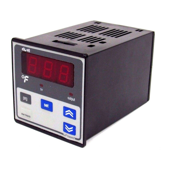
FRONT KEYPAD
SET: with this button the setpoint value
can be displayed. To change the value, this
button should be activated together with
the "UP" or "DOWN" button. In case para-
meter "dro" is set at "S", the setpoint value
(SV) can be changed with the "UP" or
"DOWN" button only, while the process
temperature (PV) can be displayed with the
"SET" button.
UP: used to increase the setpoint value, as
well as the parameter when in program-
2
;
ming. When held down for a few seconds,
the change rate accelerates.
DOWN: same functions except to de-
crease a value.
PRG: programming access button. To ac-
cess programming, this button must be
pushed together with the concealed but-
ton located under "PRG" and "SET", all at
the same time.
Led "OUTPUT": status light of the output.
Led "SV" (Set Value): to indicate that the
Set Value (SV) is displayed. This occurs
when "SET" is pushed (parameter "dro"
set at "P"); it will stay on steady if parame-
ter "dro" is set at "S".
rel. 12/96 ing
PARAMETER PROGRAMMING
Access the programming by pushing
"PRG", then the concealed button below
"PRG" and "SET", all at the same time.
The first parameter will appear and the
"OUTPUT" status light will blink throughout
the programming. Select the desired para-
meter with the "UP" and "DOWN" button.
With the "SET" button, the actual setting of
each parameter is displayed. To change a
parameter setting, push the "SET" plus the
"UP" (or "DOWN").
To exit the programming, push "PRG" plus
the concealed button.
DESCRIPTION OF PARAMETERS
Any parameter which does not apply to a
particular instrument version is automati-
cally removed from the programming
menu.
E.g.: a control for Thermocouple input will
not offer parameters "Lci" and "Hci".
d1: differential setpoint 1.
The switching differential (hysteresis) can
be set with positive value (make on rise) or
with negative value (make on fall). See pa-
rameter "HC1".
LS1: Lower Set 1.
This is the lower limit below which the user
cannot change the setpoint; normally set
at the lowest value recommended for the
sensor.
HS1: Higher Set 1.
Similar to "LS1", however setting an upper
limit for the setpoint.
Pb: Proportional band.
Only for models with PID option. This val-
ue, expressed in degrees, determines the
band-width around the setpoint within
which the instrument provides proportion-
Advertisement
Table of Contents

Related Manuals for Eliwell EWTR 910


Summary of Contents for Eliwell EWTR 910
- Page 1 12/96 ing controllers one output 72x72 GENERAL DESCRIPTION PARAMETER PROGRAMMING The EWTR 910 is a new series of micro- Access the programming by pushing processor based and fully programmable “PRG”, then the concealed button below process controllers for single setpoint ap- “PRG”...
- Page 2 DEFAULT SETTINGS - STANDARD MODELS (only for models with this option; see para- meter “AOF”). Parameter Description Range Default Unit CAL: CALibration. differential set 1 min / max 1 (C) / –1 (H) various This offers an adjustment up or down of the read-out, if needed.
- Page 3 CONNECTIONS ever the following: - the “Proportional action” activates the output in direct proportion to the shift in EWTR 910 stable system temperature; - the “Derivative action” effects the output depending on the speed of temperature Pt100 / Ni100 Pt100 / Ni100 change;...
- Page 4 Inputs (depending on model): PTC / RTD (Ni100, Pt100) / TC (J, K) / 4…20 mA (Ri = 41 Ω) for EWTR 910, EWHS 28/31 for EWHR 910 and EWPA 007/030 for EWPR 910. Resolution: 1 °C (°F) or 0.1 °C (°F). The right-most digit can also be set to read-out in 0 or 5 only, or in all 10 digits.
Need help?
Do you have a question about the EWTR 910 and is the answer not in the manual?
Questions and answers
ESTOY EN COLOMBIA, DONDE PUEDO CONSEGUIR EL CONTROLADOR DE TEMPERATURA EWTR 910