
Related Manuals for Forehorse FEM3


Summary of Contents for Forehorse FEM3
- Page 1 LCD Display FEM3 User’s Manual China· Suzhou Forehorse Electronics Technology Ltd., Co...
-
Page 2: Table Of Contents
Text of Contents Preface........................... 1 Dimensions ..........................1 Parameter ..........................2 Installation Instructions......................2 Function switch and User settings ..................2 Normal Display Area ......................3 Button definition ........................4 Preparation before starting ..................... 5 Startup and Shutdown ......................5 Function Switch ........................ -
Page 3: Preface
1 Preface Dear User: Please drive E-bike safely .The FEM3 instrument is one of the components to operate an E-bike and to control cycling status. Please read instructions carefully before using. Here we write the professional manual in order to make you understand its materials, installation, setup, adjustment, maintenance and normal use of the instrument clearly. -
Page 4: Parameter
Note :Inside diamneter could be adjusted by rubber o ring. ΦD=22.2mm/25.4mm/31.5mm 3 Parameter Transmit Transmission >2M Supply Voltage 3.3V-4.2V Frequency 2.4-2.5GHz Distance Band Working Waterproof 25mA Shell Material IP65 Current Grade Working Display window Transparent Acylic -25℃-80℃ Environment Material panel 4 Installation Instructions 1.Open the display package, and take out LCD display and its components. -
Page 5: Normal Display Area
Function switch: Riding gear shift , Assist Mode, Backlight turn on or off, Multi-function display switch, ODO/Trip/Single riding time, Trip/ Single riding time clearing, Battery display, Fault code display. Level 1 setting:Miles/Km, Speed limit, Wheel diameter, Auto power-off time, Total gear, Backlight brightness, Sleep time settings. -
Page 6: Button Definition
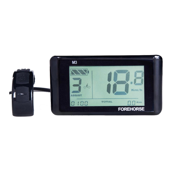
2. Assist Mode 3. Brake power off 4. LCD display battery level 5. Mileage Mode 6. Mileage 7. mileage unit 8. Speed unit 9. Speed 10.Cycling mode: Walking Assist Mode Normal Mode Rapid Cycling Mode 7 Button definition The LCD display have the all-in-one button key,installing on its throttle. Its shape and location shown as belowing:... -
Page 7: Preparation Before Starting
During the subsequent description, the up button called "MODE"; the middle button called "+" ,and the bottom button called "-" instead. 8 Preparation before starting Make sure the battery is energized and turn on the battery switch or the electric vehicle power switch. 9 Startup and Shutdown Press "MODE"... -
Page 8: Riding Mode Switch
6. battery Level display 7. Fault code display 10.1 Riding Mode Switch During the power-on status,short press the button“+” to add one mode,similarly, short press the button “-”to decrease one mode. 10.2 Assist Mode During the power-on status, long press the button “-” for three seconds, and then enter assist mode. -
Page 9: Trip/Odo/Trip Riding Time Switch
10.4 Trip/ODO/Trip Riding Time Switch In the power-on state, press the "MODE" button to switch Trip /ODO/ Trip riding time. Setting interface as shown below: 10.5 Trip/Trip riding time Clear Setting During the power-on state, long press the button “M” and “-” at the same time for 2 seconds, trip and single riding time is cleared. -
Page 10: Fault Code Display
The remaining battery capacity display interface as shown below: 10.7 Fault Code Display when the E-bike electronic control system fails, the FEM3 instrument will automatically display the fault code. The definition of the table and fault code display interface as shown below: The definition of the Fault code shown as below:... -
Page 11: User Settings
Turn fault Current sensor fault Low voltage Speeed sensor fault protection Over voltage Battery communication fault protection Motor Hall singal Instrument communication Line fault fault Motor Phase line fault Note: Only the fault is solved, the instrument can exit from the fault code display . -
Page 12: Speed Limit Setting
11.2 Speed Limit Setting Short press "MODE" button, switch to interface “P02” to enter the speed limit setting. Short press "+" button to increase the limited speed, or press "-" button to decrease limited speed Limited speed range is 15-50 Km/h. The setting interface is as following: Note: when the wheel speed arrives or exceeds the set value, the output power for motor is continously reduced. -
Page 13: The Total Stall Setting
The setting interface showing as following: 11.4 The Total Stall Setting After setting the wheel diameter, press "MODE" button to enter the total stall setting, press "+" button to increase the total number of stalls, and press "-" button to decrease the total number of stalls, setting range: 0 -9. The setting interface as shown below: Note: The total stall does not include the 0 stall and L. -
Page 14: The Backlight Brightness Setting
11.5 The Backlight Brightness Setting After setting the total stall, short press "MODE" button to enter the backlight brightness settings; press "+" button to increase the backlight brightness and press "-" button to decrease the backlight brightness. Setting range: 1-9. Setting interface as shown below: 11.6 Automatic Power-off Time Setting... -
Page 15: Sleep Setting
Setting interface as shown below: 11.7 Sleep Setting After setting the power-off time, short press “MODE” button to enter the sleep setting. Setting range: 0-9 min. Number ”0” means no sleep setting.During the sleeping status, press any button to wake up the instrument. -
Page 16: Exit Level 1 Settings
11.8 Exit Level 1 Settings After the sleep setting, short press the “MODE” button to exit Level 1 settings. Or in any type of level 1 settings, long press “MODE” button , three seconds later we can exit level 1 setting. 12 Level 2 Settings During Level 1 settings states, long press key “+”... -
Page 17: Exit Level 2 Setting
1). Long press the button ”M” and the button “+”, we entering the ID auto-search status. 2). ID number is composed of 8 digits number. It completes the automatical ID number matches until the previous seven numbers do not flash. 3). -
Page 18: Power-On Password Settings
13.1 Power-on Password Settings The power-on password is composed of 4 numbers. Firstly set the fourth number . Short press the key “+” or key “-” to set password. After complete the fourth bit, short press the button “M” to set the third password bit. And so on until the completion of the first bit setting. -
Page 19: Turn On Or Off Stall L Setting
13.3 Turn on or off Stall L Setting After Turn on or off power-on password setting, short press the button “M” for entering into ‘turn on or off stall L setting’ . Short press the key “+” or key “-” to set “On”... -
Page 20: Commitment To Quality And Warranty
3. Fails due to force majeure (such as fire, earthquake, etc.) or natural disasters (such as lightning, etc.) caused . 4. exceed the warranty period Warranty period: from the factory within 18 months. Add: No. 211 Zhujiang S. Rd, Suzhou, China Web: www.forehorse.com Tel: 0512-66312718 Fax: 0512-66312708...
Need help?
Do you have a question about the FEM3 and is the answer not in the manual?
Questions and answers