
Related Manuals for RMG 720


Summary of Contents for RMG 720
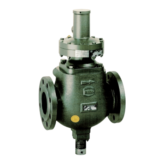
- Page 1 Safety Shut-Off Valve RMG 720 Operation and Maintenance, 720.20 Spare Parts edition 08/1991 Serving the Gas Industry - WORLDWIDE...
- Page 2 720.20 S.02...
- Page 3 Measuring units K 1a, K 2a (for incorporation into RMG 720 DN 25, and into RMG 300, RMG 330, RMG 332 as well as RMG 402) Screw out locking cap (1), turn upside-down, screw...
- Page 4 Tripping tests with the measuring units K4, K5, K6 incorporated in the gas pressure regulator ATTENTION RMG 402 must not be made as long as the locking cap (201) is screwed on to the valve stem (207). 720.20 S.04...
- Page 5 - press the O-ring fully into the groove. • Shim (138, 234) The shim serves to adjust the tripping device to its exact zero position. After any replacement of the diaphragm, the shim must be re-integrated unchanged. 720.20 S.05...
- Page 6 Tighten the screws (9, 148) and nuts (51, 58, 113, 213) by torque wrench to the torque levels of the table below: torque figues M in Nm screws and nuts SAV RMG 720 sub-unit for incorporation sub-unit for incorporation into RMG 300, 330, 332 into RMG 402, 408 size DN size DN inlet size DN item no.
- Page 7 • Tools for assembly and adjustment type size for item no. tool no. description RMG stock no. tool for assembly RMG 720 DN 25 RMG 300 DN 25 pliers A 19 DIN 5254 00 026 531 RMG 330 DN 25 and DN 50...
- Page 8 Measuring units K 1a / K 2a 4.1.1. Spare parts drawing of K 1a / K 2a 4.1.1.1. Drawing for RMG 720, DN 25 and RMG 402, DN 25 measuring unit for overpressure and underpressure release K 1a K 2a...
- Page 9 4.1.1.2. Drawing for RMG 300, DN 25, and for RMG 330, RMG 332, DN 25 and DN 50 RMG 330, RMG 332 RMG 300 *) parts to be kept in stock for maintenance 720.20 S.09...
- Page 10 4.1.2. Spare parts list for K 1a / K 2a 4.1.2.1. List for RMG 720, DN 25 and RMG 402, DN 25 (inlet size) Parts marked by an asterisk (*) to be kept in stock for maintenance: RMG stock no.
- Page 11 10 022 971 4.1.2.2. List for sub-units for incorporation into RMG 300, DN 25 and for RMG 330 and RMG 332, DN 25 and DN 50 Parts marked with an asterisk (*) to be held in stock for maintenance: RMG stock no.
- Page 12 Spare parts drawing of K4, K5, K6 4.2.1.1. Drawing for RMG 720, DN 50 to DN 100, for RMG 330 and RMG 332, DN 80 and DN 100, and for RMG 408, DN 50/100 to DN 100/200 measuring unit K4 for...
- Page 13 4.2.1.2. Drawing for RMG 402, DN 50 to DN 100 (inlet size) measuring unit K4 for measuring unit K4 for overpressure and underpressure release overpressure release only special version (without diaphragm rupture safety protection) measuring unit K6 for underpressure release only *) parts to be kept in stock for maintenance 720.20 S.13...
- Page 14 4.2.2.1. Spare parts list for K4, K5, K6 List for RMG 720, DN 50 to DN 100, for RMG 330 and RMG 332, DN 80 and DN 100, and for RMG 408, DN 50/100 to 100/200 Parts marked by an asterisk (*) to be held in stock for maintenance: RMG stock no.
- Page 15 RMG stock no. item material description DN 50 DN 80 DN 100 setpoint spring: colour: wire dia. Ø 1,1 light blue 10 000 868 10 000 868 10 000 868 wire dia. Ø 1,4 black 10 001 760 10 001 760...
- Page 16 10 008 594 protection cap 00 026 363 00 026 363 00 026 363 Parts of sub-unit for incorporation into RMG 330 and RMG 332, DN 80 and DN 100: 124* O-ring 00 020 266 00 020 268 hexagon nut...
- Page 17 10 008 535 00 018 694 230* sealing ring 00 018 694 00 018 694 10 022 971 tripping valve RMG 919-1 10 022 971 10 022 971 10 008 616 232* switch bush 10 008 616 10 008 616...
- Page 18 Remark: It is possible to integrate the tripping valve RMG 919 (see item 168, page 15) into formerly delivered SAV-units. In this case the throttling port should be rebored to at least 4 mm. 720.20 S.18...
- Page 19 Special features Spare parts drawings 6.1. Remote release upon current supply 6.1.1 6.1.2. Manual release 720.20 S.19...
- Page 20 6.1.3. Remote release and manual release upon current supply manual release 313 / 314 remote release 313 / 314 313 / 314 311 / 312 720.20 S.20...
- Page 21 6.1.4. Electric remote indication a) for K 1a / K 2a b) for K4, K5 and K6 The regulator RMG 402 is equipped with a proximity switch integrated in the main valve body (see leaflet 402.20): 720.20 S.21...
- Page 22 00 024 059 screwed socket 00 030 113 cap nut 00 030 804 cutting ring 00 030 904 contact valve RMG 912 10 005 070 307* sealing ring 00 018 694 screwed socket 00 030 038 contact valve RMG 912...
- Page 23 720.20 S.23...
- Page 24 Telephone (++49) 561 5007-0 • Fax (++49) 561 5007-207 design and assembly of gas pressure regulating and metering stations The RMG Group of Companies on the internet: http://www.rmg.de Serving the Gas Industry - WORLDWIDE We reserve the right for technical changes...
Need help?
Do you have a question about the 720 and is the answer not in the manual?
Questions and answers