Table of Contents
Advertisement
Advertisement
Table of Contents

Related Manuals for Hydrotech HSF2200 Series

Summary of Contents for Hydrotech HSF2200 Series
- Page 1 Discfilter HSF2200 - series , PFLC Operation and maintenance manual...
-
Page 2: Table Of Contents
2.2 CE marking 2.3 Conversion 2.4 Personnel requirements 2.5 Emergency stop 2.6 Electrical safety 2.7 Safety instructions 3. HYDROTECH DISCFILTER HSF2200 SERIES 3.1 Reception 3.2 Storage 3.3 Overview 3.3.1 HSF2200 type 1, filter with tank 3.3.2 HSF2200 type 2, filter without tank 3.4 Identifying the filter... - Page 3 6.3 Filtration and backwash process 7. MAINTENANCE/SERVICE 7.1 Backwash system 7.1.1 Servicing conventional nozzles 7.1.2 Self-cleaning nozzle 7.2 Cleaning the Hydrotech wash water filter 7.3 Bearings 7.3.1 Lubrication of swivel 7.3.2 Lubricating drum bearings 7.3.3 Checking drum bearing wear 7.4 Filter panels...
- Page 4 7.5.2 Adjusting drive chain tension 7.5.3 Replacing the drive chain 7.6 Drive unit 7.7 Inlet gasket 7.7.1 Checking the inlet gasket 7.7.2 Replacing the inlet gasket 8. MAINTENANCE SCHEDULE Symbols used on Hydrotech filters Manuals & technical information Operation and maintenance, Discfilter HSF2200-series PFLC...
-
Page 5: Introduction
1. INTRODUCTION This manual contains instructions for the operation and maintenance of Hydrotech Discfilters in the HSF2200 series with PFLC automation. Pay attention to all warning symbols that appear in this manual. If this information is ignored it may result in serious personal injury and/or damage to equipment. -
Page 6: Safety Instructions
2. SAFETY INSTRUCTIONS Hydrotech Discfilters in the HSF2200 series are designed for safe operation provided they are in- stalled correctly and used in accordance with the enclosed instructions. The equipment must be installed correctly and adapted in accordance with local regulations. This equipment is designed for use by one or more operators. -
Page 7: Personnel Requirements
The filter tank or the frame must be connected to ground. Also see section 4.4. The main power switch/emergency stop must be fitted Figure 2.3 Hydrotech control cabinet PFLC. in accordance with applicable regulations. A. Mode selector B. Main power switch 2.7 Safety instructions... - Page 8 The drum can start rotating without warning if automatic control is activated. Moving parts must not be touched. Safety guards are fitted around the power transmission. Make sure these are secured and cor- rectly fitted. Spray from the backwash water may contain harmful substances. Measured noise levels from the filter are less than 74 dB (A).
-
Page 9: Hydrotech Discfilter Hsf2200 Series
3. HYDROTECH DISCFILTER HSF2200 SERIES 3.1 Reception Once the equipment has been delivered and received it must be checked for transport damage. Document any transport damage before further handling of the equipment. The consignme- nt note, manual and spare part kit are attached to the equipment. Check all parts against the consignment note. -
Page 10: Overview
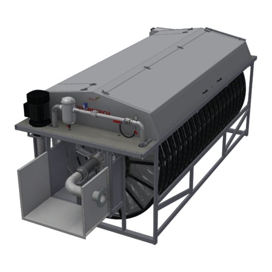
3.3.1 HSF2200 type 1, filter with tank NB Also see section 3.3.2 (HSF2200 type 2, filter without tank) where several filter parts are shown. Figure 3.1 Hydrotech Discfilter in HSF2200 series type 1 (side view). A. Inlet side B. Filter cover C. - Page 11 Figure 3.3 Hydrotech Discfilter in HSF2200 series type 1 (outlet side). A. Bypass valve for nozzle check B. Manometer C. Lubrication point D. Shut off valve for backwash pipe E. Backwash ramp lever F. Drive unit G. Pressostat - dry running protection for pump (optional) H.
-
Page 12: Hsf2200 Type 2, Filter Without Tank
3.3.2 HSF2200 type 2, filter without tank Figure 3.5 Hydrotech Discfilter in HSF2200 series type 2 (side view). A.Inlet side B. Inlet passage C. Filter cover D. Outlet side Figure 3.6 Hydrotech Discfilter in HSF2200 series type 2 (inlet side). - Page 13 Figure 3.7 Hydrotech Discfilter in HSF2200 series type 2 (outlet side). A. Backwash ramp lever B. Lubrication point C. Drive unit D. Drum lifter E. Drive chain F. Drum bearing, outlet side G. Drum H. Filter panel Operation and maintenance, Discfilter HSF2200-series PFLC...
-
Page 14: Identifying The Filter
3.4 Identifying the filter Filter type, serial number and year of manufacture are stated on the marking plate. The filter type and serial number are also stated on the front of this manual. Figure 3.8 Filter marking plate. 3.4.1 Definition of filter type Figur 3.9 Definition of filter type Operation and maintenance, Discfilter HSF2200-series PFLC... -
Page 15: General Installation Instructions
WARNING! The work area must be fenced off before unloading, in accordance with local regulations, to prevent unauthorised access. Figure 4.1 Lifting Hydrotech Discfilter in HSF2200 series type 1 (with tank). Operation and maintenance, Discfilter HSF2200-series PFLC... - Page 16 Filters without a tank can be lifted using a crane or overhead crane by using the filter’s lifting lugs. Figure 4.2 Shows how lifting devices are attached (filter without tank). Figure 4.3 Lifting Hydrotech Discfilter in HSF2200 series type 2 (without tank). Operation and maintenance, Discfilter HSF2200-series PFLC...
-
Page 17: Installation Site
4.2 Installation site 4.2.1 Outdoor installation In the event of outdoor installation it is important to protect the filter panels against direct sun- light, as heat and UV radiation otherwise can cause damage to the filter panels. The same applies to the control panel touch screen. -
Page 18: Equipotential Bonding
4.4 Equipotential bonding The Hydrotech Discfilter and associated equipment should be protected with a suitable system for equipotential bonding. This is very important to prevent galvanic corrosion. Ideally use a ca- ble with a cross section of 10–16 mm2. The cable should be connected to the same electrical potential as the drive system. -
Page 19: Start Up And Operation
5. START UP AND OPERATION 5.1 Check procedures during start-up 1. Check that the drive unit cover is installed correctly. 2. Set the mode selector to the HAND position (see F in Figure 5.2). 3. Set the main power switch to the ON (1) posi- tion (see I in Figure 5.2). -
Page 20: Automatic Settings
5.2 Automatic settings The control system for the HSF2200 series must be equipped with a frequency converter on the drive unit. This is factory calibrated if delivered from Hydrotech. To perform a soft start of the drive motor, the frequency converter settings must be min. 5 sec “ramp up” and min. 3 sec ”ramp down”. - Page 21 Figure 5.3 Component parts of the Hydrotech control cabinet. A. Line breaker B. Automatic circuit breaker C. Fuses D. Mains supply (24 V) E. Contactor, pump F. Contactors, HPC drive unit (optional) G. Relay H. Level relay, flush valve (optional) I.
-
Page 22: Level Differences
5.2.1 Level differences The maximum permitted difference between the water levels inside and outside the drum is 250 mm during normal operation (see Figure 5.4). The recommended level difference is 100– 200 mm. If an even flow after the filter is required, the filter must be run with a small level difference. -
Page 23: Service Mode Hand
5.2.4 Service mode HAND HAND is only a service mode. In order to operate the filter in HAND mode, the following steps must be implemented: 1. Turn the mode selector shown in Figure 5.2 to the HAND position. 2. Once the mode selector has been turned to HAND, “HAND”... -
Page 24: Function
The filter is not a pressure vessel. 6.2 Non-intended use Unless approved in writing by Hydrotech, the filter must not be used to filter liquids other than water. The filter must not be installed in an environment with an explosive atmosphere or another risk of explosion, such as high concentrations of dust. -
Page 25: Maintenance/Service
7. MAINTENANCE/SERVICE 7.1 Backwash system The most common cause of operating disruptions in the backwash system is clogged nozzles. Clogging is caused by particles in the wash water and/or by e.g. biofouling in the pipe system. There are also nozzles that are self-cleaning and less sensitive to blocking than the conventional nozzles, see section 7.1.2. - Page 26 8. Check whether any of the nozzles are clogged by checking whether water runs through them. Clogged nozzles are cleaned as follows: Figure 7.3 Nozzle components. A.Nozzle attachment B. Rubber seal C. Nozzle tip D. Nozzle nut E. O-ring 9. Remove the nozzle nut by turning it a ¼ turn anticlockwise. Exercise care not to lose the rubber seal.
-
Page 27: Self-Cleaning Nozzle
7.1.2 Self-cleaning nozzle Figure 7.4 below shows a self-cleaning nozzle. Figure 7.4 Nozzle components, self-cleaning nozzle. A. Set screw B. Nozzle attachment C. O-ring D. O-ring E. Nozzle tip F. Nozzle nut Operation and maintenance, Discfilter HSF2200-series PFLC... -
Page 28: Cleaning The Hydrotech Wash Water Filter
7.2 Cleaning the Hydrotech wash water filter NB Prior to servicing, read section 2.7. If the pressure gauge indicates a pressure that is more than 0.5 bar below normal pressure, it’s time to clean the wash water filter. 1. Turn the main power switch to the OFF (0) position and lock with a padlock. -
Page 29: Bearings
7.3 Bearings NB Prior to servicing, read section 2.7. Stickers indicating the lubrication points are attached to the filter, see Fi- gure 7.6. Figure 7.6 7.3.1 Lubrication of swivel The swivel makes up the bearing between the backwash pipe and the connecting pipe for the backwash water (see Figure 7.7). -
Page 30: Checking Drum Bearing Wear
7.3.3 Checking drum bearing wear 1. Turn the main power switch to the OFF (0) position and lock with a padlock. 2. Drain the chamber/filter tank. 3. Check the drum bearings with respect to wear. If the distance between the bearing housing (A) and the shaft (B) is less than 22 mm (see Figure 7.8), the drum bearing must be replaced. -
Page 31: Filter Panels
7.4 Filter panels NB Prior to servicing, read section 2.7. 7.4.1 Additional cleaning Additional cleaning of the filter panels may be necessary. The need for additional cleaning be- comes clear if the frequency of automatic backwash starts increases. Additional cleaning can be chemical cleaning or cleaning with a high pressure washer. -
Page 32: Chemical Cleaning Of Filter Panels
For more detailed instructions, please contact your supplier. Hydrotech Discfilters in the HSF2200 series as standard are prepared with a chemical ramp to make removal of long-term clogging of the filter media possible. The Hydrotech chemical trolley HCT (option) is connected to the chemical ramp connection (see Figure 3.2 and Figure 3.6). - Page 33 If necessary clean the chemical ramp nozzles as described below: 1. Turn the main power switch to the OFF (0) position and lock with a padlock. 2. Remove the nozzle by turning it ¼ turn anticlockwise (see Figure 7.13). 3. Clean the nozzle with compressed air or a plastic brush. Never use a wire brush, metal pins or similar as these can damage the nozzle.
-
Page 34: Changing Filter Panels
7.4.4 Changing filter panels When replacing the filter panels it is important to maintain the balance of the drum. Remove/ refit every other filter panel. This prevents unintentional rotation of the drum and reduces the load on the drive chain and gearbox. Figure 7.14 Correct way of changing filter panels. - Page 35 5. Undo the filter segment cover screws and remove the cover, see Figure 7.18). Figure 7.18 The filter segment cover is removed. 6. Pull out the filter panel (see Figure 7.19). Figure 7.19 The filter panel is pulled out. Operation and maintenance, Discfilter HSF2200-series PFLC...
- Page 36 7. Insert a new filter panel and press in until it touches the bottom. NB Filter panels with steel frames must be po- sitioned with the filter cloth facing inwards (see Figure 7.20). Incorrect installation of the filter panels can cause damage to the filter segments. 8.
-
Page 37: Drive Chain
7.5 Drive chain NB Prior to servicing, read section 2.7. The filter is equipped with a chain drive. For technical data, see Appendices A and D. 7.5.1 Checking the drive chain 1. Turn the main power switch to the OFF (0) position and lock with a padlock. 2. -
Page 38: Adjusting Drive Chain Tension
7.5.2 Adjusting drive chain tension Adjust the drive chain tension as follows: 1. Turn the main power switch to the OFF (0) position and lock with a padlock. 2. Loosen the four nuts (A) (see Figure 7.22). 3. Loosen the nut (B). 4. -
Page 39: Replacing The Drive Chain
7.5.3 Replacing the drive chain 1. Turn the main power switch to the OFF position and lock with a padlock. 2. Lower the drive unit to its lowest position, see section 7.5.2. 3. Split and remove the drive chain. 4. Fit the new drive chain. 5. -
Page 40: Replacing The Inlet Gasket
7.7.2 Replacing the inlet gasket 1. Turn the main power switch to the OFF (0) position and lock with a padlock. 2. Lower the water level in the filter until the whole inlet gasket is accessible. 3. Note how the inlet gasket is fitted before it is dismantled. 4. -
Page 41: Maintenance Schedule
8. MAINTENANCE SCHEDULE Check/Action Maintenance interval Check whether the wash water filter is clogged. See The interval is based on experience from the app- section 7.2. lication in question. (When the backwash water pressure drops 0.5 bar below the normal value.) Check the filter panels for clogging and damage. -
Page 42: Symbols Used On Hydrotech Filters
Symbols used on Hydrotech filters Symbol is displaying equipotential earth bonding points on the filter. Symbol shown at lubrication points on the filter. Read the manual for fur- ther information about lubrication. Symbol displaying moving parts. Neg- ligence to comply with safety regula- tions may lead to injury. -
Page 43: Manuals & Technical Information
For further technical information please visit http://technomaps.veoliawatertechnologies.com/ hydrotech/en/. Click on ”Manuals & technical information” in the list on the left side. Hydrotech microscreen filters webpage Select the product you want more information about and it will open a Pdf in a new tab. You can also find information regarding products used on Hydrotech filters, e.g. - Page 44 Hydrotech AB A Veolia Solutions & Technologies Company Mejselgatan 6 235 32 Vellinge Sverige Telefon: +46 (0)40 - 42 95 30 Fax: +46 (0)40 - 42 95 31 E-mail: mailbox@hydrotech.se Hemsida: www.hydrotech.se Copyright © All rights reserved Operation and maintenance, Discfilter HSF2200-series PFLC...
Need help?
Do you have a question about the HSF2200 Series and is the answer not in the manual?
Questions and answers