Table of Contents
Advertisement
Quick Links
Advertisement
Table of Contents

Related Manuals for APAR AR601

Summary of Contents for APAR AR601
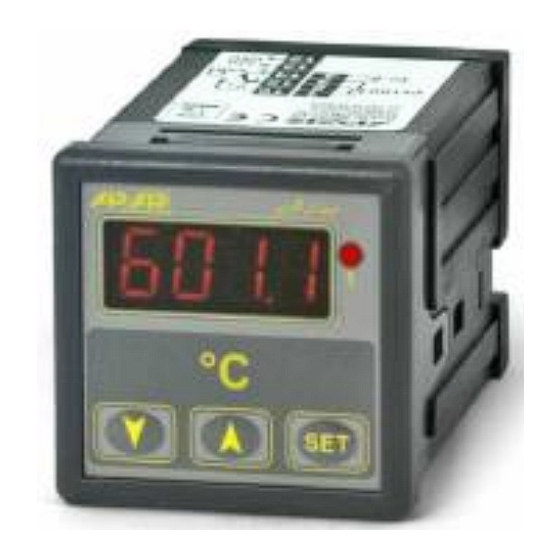
- Page 1 User Manual Temperature Controller AR601 Version 3.1 2013.02.13...
-
Page 2: Table Of Contents
In case of additional questions please contact our technical advisor. Table of contents SAFETY PRECAUTIONS..............3 INSTALLATION INSTRUCTIONS............3 AR601 CONTROLLER GENERAL CHARACTERISTICS......3 TECHNICAL SPECIFICATIONS............. 4 IMPORTANT USAGE INFORMATION..........5 HOUSING AND INSTALLATION METHOD......... TERMINAL STRIPS AND ELECTRICAL CONNECTIONS DESCRIPTION. 6 BUTTONS, DISPLAY AND LED DESCRIPTION........ -
Page 3: Safety Precautions
Avoid proximity of remote controlled devices, electromagnetic meters, high power loads, loads with phase or group power regulation and other devices that generate large impulse disturbances. 3. AR601 CONTROLLER GENERAL CHARACTERISTICS Universal thermoresistance measurement input Pt100 and thermocouple J, K, S ... -
Page 4: Technical Specifications
4. TECHNICAL SPECIFICATIONS Universal input (keyboard selection), display and regulation range: Pt100 (3- or 2-wires)....-100 ÷ 850°C (factory input setting) Thermocouple J......0 ÷ 800°C Thermocouple K......0 ÷ 1200°C Thermocouple S......0 ÷ 1600°C Electronic temperature compensation for thermocouple cold ends Pt100 lead resistance...... -
Page 5: Important Usage Information
5. IMPORTANT USAGE INFORMATION – suppression systems use If inductive load is connected to relay contacts (i.e. contactor coil or transformer) then during its contacts disconnection surges and electric arc often occurs. They are caused by discharge of energy stored in the inductor. The most negative effects of these surges are: reducing the life of the contactors and relays, destruction of semiconductors (diodes, thyristors, triacs), measurement and control systems damage or distortion, emission of electromagnetic field that interferes local devices. -
Page 6: Terminal Strips And Electrical Connections Description
7. TERMINAL STRIPS AND ELECTRICAL CONNECTIONS DESCRIPTION Connectors Description 1-2-3 Pt100 input (2- and 3- wires) Thermocouple input TC (J, K, S) 12-13 Power supply input 230Vac 14-15-16 P1 relay output or SSR1 8. BUTTONS, DISPLAY AND LED DESCRIPTION Controller has 3 buttons: Parameter value display (marked as SET in manual) Preset value display and change mode enter (see section 9) Displayed errors deleting... -
Page 7: Output Setpoint Value Display And Change
9. OUTPUT SETPOINT VALUE DISPLAY AND CHANGE When in measured value display mode, short press SET button to display SET1 message: Next press SET button to display (preview) setpoint value Press SET button together with UP or DOWN, to change setpoint value (if settings lock is not turned on, parameter 17 - , see table 1, chapter 10) Exit setting mode: press and hold UP and DOWN buttons simultaneously for 5 seconds. -
Page 8: Messages And Errors List
Output 1 status out of no changes, measurement range (3) Output 1 characteristics OFF, HEATING COOLING Output 1 setpoint Within range ÷ Output 1 hysteresis Zero shift Magnification PID proportionality range - turn off PID action) integration time constant s, ( - turn off integration) (PID) derivative time constant... -
Page 9: On-Off Characteristics Types
12. ON-OFF CHARACTERISTIC TYPES CAUTIONS: Parameter name Parameter number (p. 10, table 1) 13. PID REGULATION Controller works in PID mode when proportionality range (parameter 12: ) is different than zero. Proportionality range position relative to set value is shown on illustrations a) and b). Influence of integral and derivative part of PID regulation is set by parameter 13: and 14:... -
Page 10: Pid Autotuning
14. PID AUTOTUNING Autotuning automatically selects PID parameters and consists of following stages: Tuning start delay (about 1 minute, time for actuator power on, i.e. heating power, cooling power, fan,...), determining object characteristic, calculating and saving in non-volatile controller memory parameters , start of regulation with new PID parameters. -
Page 11: Manual Pid Parameters Selection
15. MANUAL PID PARAMETERS CONFIGURATION Following algorithm allows PID action parameters choice – proportionality range (parameter 12), integration time , (13), differentiation time (14) and pulsation period (15). 1. Set regulator to ON-OFF mode (parameter = 0), threshold required value and =0.
Need help?
Do you have a question about the AR601 and is the answer not in the manual?
Questions and answers