
Subscribe to Our Youtube Channel
Summary of Contents for LABEL-AIRE 3115NV
- Page 1 3115NV Manual 3115NV Rev.01 P/N 7408830‐100 2010 for parts & service call QLC (800) 837-1309...
- Page 2 for parts & service call QLC (800) 837-1309 2 ...
-
Page 3: Table Of Contents
TABLE OF CONTENTS INTRODUCTION…………………………………………………………………………………………………………………………………………………………………… 5 CAUTIONARY SYMBOLS AND PICTOGRAMS………………………………………………………………………………………………………………………….. 7 INITIAL WARNINGS…………………………………………………………………………………………………………………………………………………………... 9 APPLICATOR POWER CABLE…………………………………………………………………………………………………………………………………………….. 10 MECHANICAL PLACEMENT OF THE MACHINE…………………………………………………………………………………………………………………... 11 GENERAL MACHINE INFORMATION……………………………………………………………………………………………………………………………. 13 CONTROL PANEL…………………………………………………………………………………………………………………………………………………………………15 MICROPROCESSOR MESSAGES…………………………………………………………………………………………………………………………………… 21 MACHINE SEQUENCE………………………………………………………………………………………………………………………………………………….. 23 TOOL LIST………………………………………………………………………………………………………………………………………………………………………….. 24 CONNECTION TO A.C. POWER……………………………………………………………………………………………………………………………………. 25 INITIAL SETUP………………………………………………………………………………………………………………………………………………………….. 26 LABEL SETUP……………………………………………………………………………………………………………………………………………………………. 27 LABEL SENSOR EDGE………………………………………………………………………………………………………………………………………………………… 31 LABEL REPEAT LENGTH…………………………………………………………………………………………………………………………………………………….. 32 LABEL STOP POSITION……………………………………………………………………………………………………………………………………………….. 33 IMPRINTER INSTALLED……………………………………………………………………………………………………………………………………………………… 3 5 PRINTER DWELL TIME………………………………………………………………………………………………………………………………………………………..36 ENCODER PULSE RESOLUTION………………………………………………………………………………………………………………………………………….. 37 SPEED FOLLOWING…………………………………………………………………………………………………………………………………………………………… 38 PRODUCT SETUP………………………………………………………………………………………………………………………………………………………………. 40 POSITIONING THE APPLICATOR………………………………………………………………………………………………………………………………………… 4 1 INITIAL SETUP…………………………………………………………………………………………………………………………………………………………. ... - Page 4 APPENDICES………………………………………………………………………………………………………………………………………………………………. 74 APPENDIX C……………………………………………………………………………………………………………………………………………………………….. 93 MAINTENANCE………………………………………………………………………………………………………………………………………………………… 103 Figure 1 115V Power Cable ................................10 Figure 2 220V Power Cable ................................ 1 0 Figure 3 Applicator Support Structure ............................ 1 2 Figure 4 3115NV APPLICATOR .............................. 1 3 Figure 5 ‐ Electrical Panel (Rear of Machine) .......................... 1 4 Figure 6 Control Panel ................................ 1 5 Figure 7 Peeler Plate Detail ................................ 2 8 Figure 8 Threading Diagram (Right Hand) .......................... 2 9 Figure 9 Threading Diagram (Left Hand) ............................ 3 0 Figure 10 ‐Nose Tilt Adjustment .............................. ...
-
Page 5: Introduction
INTRODUCTION The Label-Aire model 3115NV is a high speed label applicator used to apply pressure sensitive labels to moving products of the same size, such as packages on a production line. It is essentially a self contained module that may be mounted in almost any position adjacent to the production line, to apply labels to the top, sides, or bottom of packages as they pass by. - Page 6 Paragraphs that are in this style give information to help handle special circumstances, or re-emphasize important information. FOLLOW ALL SAFETY INSTRUCTIONS. The model 3115NV applicator has been provided with a number of safety features. Observe all safety warnings and under no circumstances attempt to remove or defeat safeguards or operate the machine in a manner contrary to the instructions.
-
Page 7: Cautionary Symbols And Pictograms
CAUTIONARY SYMBOLS AND PICTOGRAMS The following symbols may be encountered on or in the machine and in the Technical manuals. They serve to alert you to potential hazards that may cause serious harm to personnel. This symbol warns you that there is a danger of being injured by the drive and/or nip rollers. - Page 8 This symbol indicates that it is important to maintain a safe air pressure. This symbol indicates that you should read the Technical Manual before proceeding. (I) This symbol on an electrical power switch indicates SWITCH ON. (O) This symbol on an electrical power switch indicates SWITCH OFF. This symbol indicates the protective EARTH connection.
-
Page 9: Initial Warnings
INITIAL WARNINGS The model 3115NV has been designed with the safety of the operator and service personnel in mind. Proper safety features have been incorporated and the applicator safety tested to assure safety if used as intended. Refer to the CAUTIONARY SYMBOLS AND PICTOGRAMS definitions on the preceding pages. -
Page 10: Applicator Power Cable
APPLICATOR POWER CABLE Do not connect the machine to the AC power source until directed to do so in the set-up procedures. 115V applicators are shipped from the factory with a six foot three pin power cord. One end plugs into the IEC receptacle on the side of the applicator. -
Page 11: Mechanical Placement Of The Machine
MECHANICAL PLACEMENT OF THE MACHINE The model 3115NV is mounted at the installation site to provide a safe, adjustable and stable alignment of the label to be applied, with the product. The physical properties of the applicator are shown in Figure 3. The orientation of the applicator label dispenser can be upright and above, nose up, nose down, and reels up. -
Page 12: Figure 3 Applicator Support Structure
Figure 3 Applicator Support Structure for parts & service call QLC (800) 837-1309 12 ... -
Page 13: General Machine Information
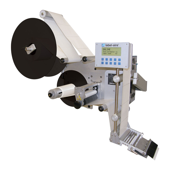
Figure 4 3115NV APPLICATOR for parts & service call QLC (800) 837-1309 13 ... -
Page 14: Figure 5 - Electrical Panel (Rear Of Machine)
Figure 5 ‐ Electrical Panel (Rear of Machine) for parts & service call QLC (800) 837-1309 14 ... -
Page 15: Control Panel
CONTROL PANEL This section covers the control panel menu items. Figure 6 Control Panel When the machine is first powered ON, the display will read: IMPAXX MACHINE SYSTEMS LABEL- AIRE NEW 3000 SERIES Then: OFFLINE PRODUCTS PER MINUTE: XXXX button will put the machine in mode, for normal operation, or mode, for set- [ENABLE]... - Page 16 The Service level allows configuration of machine specific items such as the type of machine, and activates any options the machine is equipped with. The following is the list of menu items for each level and their function for the 3115NV applicator. OPERATOR LEVEL - This is an informational display showing the product rate.
- Page 17 - This information display shows the conveyor speed. This display is only shown if LINE SPEED SPEED is set to in the Service menu. FOLLOWING - This recalls the microprocessor settings that have been stored in the RECALL PARAMETER FROM LABEL PAGE indicated label page.
- Page 18 - This setting determines where the next label to dispense stops. For example, if the LABEL STOP POSITION machine is properly set-up, the leading edge of the next label to be applied will be at the peeler bar tip. This value can be set from 0.00 to 2.00 inches.
- Page 19 The label page can be set from 1 to 50. Label pages can be set-up for each label type. SERVICE MENU - This can be set to , or . This manual covers the MACHINE TYPE 3111NV 3114NV 3115NV 3125 3135 3155 machine type. 3115NV - Set this to (English), or as desired.
- Page 20 - Set this to if the machine is being used in a Zero Down Time situation, ZERO DOWN TIME INSTALLED otherwise. When set to , it allows the setting of the function in the Advanced ZERO DOWN TIME menu. - Set this to if you wish more than one label to be applied to each MULTIPLE LABELS ON PRODUCT product, or...
-
Page 21: Microprocessor Messages
MICROPROCESSOR MESSAGES : This indicates whether the machine is ready to apply labels ( ), or in set-up mode OFFLINE/ONLINE ONLINE OFFLINE : This message informs you that you must enter the access code for the menu level ENTER CODE (Advanced or Service) in order to proceed to the next microprocessor function. : This indicates an improper value has been entered. - Page 22 : This message is displayed when a product input is received before the end of UNLABELLED PRODUCT label feed. : This message is displayed when more than 30 products are between the PRODUCT OVERFLOW peeler bar tip and the product detector. : This message is displayed when more than 30 labels are between the label peeler bar tip LABEL OVERFLOW and the label sensor.
-
Page 23: Machine Sequence
MACHINE SEQUENCE 1. Power ON. 2. Machine placed ONLINE 3. Product detector detects the edge of the product. distance elapses. LABEL ON PRODUCT POSITION 5. Label apply begins 6. Label detector detects the edge of the label. 7. Label apply ends. 8. -
Page 24: Tool List
TOOL LIST NOTE: The mounting hardware provided is USA inch size. Inch size tools are required as follows: OPEN END WRENCHES SCREWDRIVERS HEX HEAD WRENCHES 1/16 inch 7/16 inch #1 Phillips 1/8 inch 3/32 inch flat blade 3/16 inch 3/32 inch 5/32 inch 7/64 inch 9/64 inch... -
Page 25: Connection To A.c. Power
CONNECTION TO A.C. POWER Use this sequence whenever A.C. power is applied to the applicator. NOTE: Make sure that the applicator is set to the proper voltage before applying power, or damage to the equipment may result. 1. Turn OFF (O) the applicator switch. -
Page 26: Initial Setup
INITIAL SETUP When setting the machine up for the first time or when changing over to a different size, type, or shape label for the first time, begin by setting these values into the microprocessor. Set the LANGUAGE UNITS to their desired values. only if an encoder is being used. -
Page 27: Label Setup
LABEL SETUP LOADING LABELS See Appendix A for re‐loading labels. This section of them Manual explains how to thread labels through the machine. NOTE: This section of the manual explains how to adjust the machine for the label that you want to apply. The microprocessor will remember the instructions for applying the label. Because all of the adjustments affect each other, it is very important that you do the steps listed in this section in the order that they are given. -
Page 28: Figure 7 Peeler Plate Detail
Figure 7 Peeler Plate Detail for parts & service call QLC (800) 837-1309 28 ... -
Page 29: Figure 8 Threading Diagram (Right Hand)
Figure 8 Threading Diagram (Right Hand) for parts & service call QLC (800) 837-1309 29 ... -
Page 30: Figure 9 Threading Diagram (Left Hand)
Figure 9 Threading Diagram (Left Hand) for parts & service call QLC (800) 837-1309 30 ... -
Page 31: Label Sensor Edge
LABEL SENSOR EDGE 1. Place the machine OFFLINE 2. Select the menu item. This section will be set either for , which LABEL SENSOR EDGE LEAD TRAIL designates for the leading or trailing edge of the label. 3. The display should read unless the label has an odd shaped leading edge and a straighter LEAD trailing edge. -
Page 32: Label Repeat Length
LABEL REPEAT LENGTH The label repeat length tells the microprocessor the distance from the leading edge of one label to the leading edge of the next. If the machine feeds one label repeat distance without sensing a label, the microprocessor knows that the label is missing or the label sensor isn't working properly. If labels in a row are missing, the microprocessor will stop the CONSECUTIVE MISSING LABEL COUNT machine. -
Page 33: Label Stop Position
LABEL STOP POSITION Exercise caution when cycling the machine. Keep hands away from the drive rollers. This function allows you to indicate to the microprocessor the distance between detecting a label and stopping the label advance. After the machine detects a label edge, the label should advance until it is 1/8 inch beyond the edge of the peeler plate. - Page 34 6. Press and release the key until the machine advances a label, if the label isn't positioned [FEED] correctly, repeat step 4. NOTE: If the label is still flagged out too far when the display is at its minimum value move the label sensor to the other position. Go on to the Imprinter Installed Section.
-
Page 35: Imprinter Installed
IMPRINTER INSTALLED The hot stamp imprinter is used to add a date code, batch code, or other information to the labels before application to the product. The imprint occurs after the end of label feed and must be completed before the next label feed begins. -
Page 36: Printer Dwell Time
PRINTER DWELL TIME Disregard this section if is set to . Continue with the Product Set-Up Section. If IMPRINTER INSTALLED is set to , refer to the Options Section of the manual for instructions. IMPRINTER INSTALLED for parts & service call QLC (800) 837-1309 36 ... -
Page 37: Encoder Pulse Resolution
ENCODER PULSE RESOLUTION Exercise caution when cycling the machine. Keep hands away from the drive rollers. If an encoder is used, set this value to number of encoder pulses per inch of conveyor (product) travel. This value only needs to be changed if the circumference of the encoder wheel changes, or if the encoder resolution is changed. -
Page 38: Speed Following
SPEED FOLLOWING Exercise caution when cycling the machine. Keep hands away from the drive rollers. Large variations in web speed may cause the Label on Product Position to fluctuate accordingly. This function provides compensation for wide variations in web speed so that the Label on Product Position remains constant regardless of web speed. - Page 39 3115NV RH 3115NV RH for parts & service call QLC (800) 837-1309 39 ...
-
Page 40: Product Set-Up
PRODUCT SET‐UP This section of the manual explains how to adjust the machine for each type of product that you want to label. Because all of the adjustments affect each other, it is very important to do the steps that are listed in this section in the order that they are given. -
Page 41: Positioning The Applicator
POSITIONING THE APPLICATOR INITIAL SETUP a. Set the product handling system to deliver the product in a consistent position at a regular rate. b. The product spacing device, (feed screw, metering wheel, etc.) should be set-up to properly space and consistently position the product. Inconsistent spacing and positioning can result in products either being mislabeled or skipped when products are too closely spaced. - Page 42 This section explains how to prepare the applicator for set-up with labels. There are two common operation attitudes for the 3115NV applicator: "Reels-Up" and "Upright-and-Above." A Reels-Up machine labels the side of a product, while an "Upright-and-Above" machine labels the top of the product. Follow the instructions below for your machine.
-
Page 43: Upright And Above Attitude
UPRIGHT AND ABOVE ATTITUDE NOTE: Whenever you adjust the applicator or the applicator peeler plate position, make sure that the conveyor and the conveyor chain top never touch the peeler plate. Contact with the moving conveyor could cause serious and costly damage to the applicator. -
Page 44: Figure 10 -Nose Tilt Adjustment
1. Position the applicator so that labels will be dispensed in same direction that the product is traveling (the center line of the label should be parallel to the center line of the product's label panel area). 2.Loosen the nose assembly height adjustment screws and move the nose assembly up or down to position the peeler plate about 1/8 inch away from the highest point of the product labeling surface. -
Page 45: Figure 12- Upright And Above Attitude
When the applicator's angles and distances are correct and secure, go on the Product Sensor Section. Figure 12 Nose Height Adjustment Figure 11‐ Nose Height Adjustment Figure 12‐ Upright and Above Attitude for parts & service call QLC (800) 837-1309 45 ... -
Page 46: Figure 13 -Peeler Bar Adjustment
REELS-UP ATTITUDE 1. Place a properly oriented product on the conveyor in the label application area. If necessary, swing any applicator nose device (i.e., brushes, rollers etc.) out of the way so that the peeler plate is clearly visible. NOTE: Whenever you adjust the applicator or the applicator peeler plate position, make sure that the conveyor and the conveyor chain top never touch the peeler plate. - Page 47 NOTE: It is important that the peeler plate be at a 15-25° angle to the side of the conveyor, and that the peeling edge of the peeler plate be 1/8 inch from the widest point of the product. If this angle and distance are not correct, the label's placement on the product may vary.
-
Page 48: Figure 14- Wiring For Pnp And Npn Detectors
Figure 14‐ Wiring for PNP and NPN Detectors The following instructions are for the Label-Aire standard product detector P/N: 7600005-802. Follow the manufacturer’s instructions for set-up if another model product detector is used. for parts & service call QLC (800) 837-1309 48 ... -
Page 49: Figure 15 Allen Bradley
ALLEN BRADLEY THROUGH BEAM P/N 7600005802 1. Place the machine OFFLINE 2. Connect the product detector to the Product Detector connector. 3. The rear cover window on the detector must be opened before any adjustments can be made. See Figure 16. Press the flexible retaining clip against the cable to open the window. 4. - Page 50 PRODUCT DETECTOR LOCKOUT This function allows you to set a time or distance during which the microprocessor will ignore any detection signals from the product detector. Use this function when the product detector is generating false detection signals and the applicator cycles more than once per product. This may happen if a shiny product is reflecting light back to the detector.
-
Page 51: Figure 16- Peeler Plate Alignment
FINAL SET-UP Exercise caution when cycling the machine. Keep hands away from the drive rollers. Before attempting to apply labels to products, make sure that: 1. The product handling system is adjusted to present the products to the applicator in a repeatable manner at a steady pace. - Page 52 The applicator is now ready to apply labels to products. Two basic groups of products can be labeled with the 3115NV Flat products and curved products. Flat products are most common and will be described in this section. For curved products refer to Appendix C.
-
Page 53: Figure 17 -Product Detector Position
Figure 17 ‐PRODUCT DETECTOR POSITION 9. Repeat the above procedure until the label is applied at the required position on the product. 10. Stop the conveyor. Place the machine OFFLINE 11. Select the menu item. Set as low as it PRODUCT DETECTOR LOCKOUT PRODUCT DETECTOR LOCKOUT will go. - Page 54 14. If the message was displayed, the product detector detected the product or UNLABELLED PRODUCT something else that triggered the product detector. must be used to PRODUCT DETECTOR LOCKOUT ignore the false detections. After the product is detected, the is used to “lock out” or ignore the PRODUCT DETECTOR LOCKOUT erroneous product detections until the entire product has passed the product detector.
-
Page 55: Test Run
TEST RUN After all adjustments have been made, a test run should be performed to test the set-up in a dynamic mode. Exercise caution when cycling the machine. Keep hands away from the drive rollers. 1. Place the machine ONLINE 2. - Page 56 for parts & service call QLC (800) 837-1309 56 ...
- Page 57 SET-UP RECORD NOTE: If this machine is supplied with any optional equipment, refer to the Options section of the manual before proceeding with documentation. Documentation is an important step that many people overlook. Complete documentation will help you to make rapid and accurate change-over. This manual provides a form that allows you to record all of the machine settings for each label.
- Page 58 Break & Dancer Arm Adjustment Page 59 figure 1 page 59 figure 2 The inner collar adjusts the dancer arm tension 1. Loosen two Allen screws on the inside collar 2. Holding the dancer arm pull to the desired position or proximity (1 o’clock) and then slightly tighten the Allen screws so the collar will still move on the shaft then using 5/32” T‐handle push collar clockwise slightly to set into position tighten the screws back down. (As shown on page 59 figures 1& 2) NOTE: The outer collar has no adjustments the break tension is set with the dancer arm adjustment. ...
-
Page 59: Figure 18 Brake Asy Unwind
BRAKE BAND & SPRINGS Figure 18 BRAKE ASY UNWIND Figure 19 LABEL SENSOR & PEEL TIP ASY for parts & service call QLC (800) 837-1309 59 ... - Page 60 OPTIONS The following pages contain the instructions for the set-up and operation of the optional equipment available on this machine. for parts & service call QLC (800) 837-1309 60 ...
- Page 61 ALARMS Your machine may be equipped to provide an alarm output whenever it detects one of the following alarm conditions: Web Break/No Labels Found, and Low Label Supply. The Low Label alarm occurs when the label supply drops below a predetermined level. The Web Break alarm occurs when label sensor does not detect the value entered for , or if the label sensor does not detect a gap CONSECUTIVE MISSING LABEL COUNT...
-
Page 62: Figure 20- Low Label Alarm Adjustment
1. If the low label alarm detector sensitivity is properly set, the alarm light will activate. 2. If the alarm light is functioning, replace the labels on the unwind and go on to the Low Label Alarm Trigger Point. If the alarm light is not functioning properly, go on to the Low Label Sensitivity Adjustment Section. LOW LABEL ALARM TRIGGER POINT Place the offline before you perform the following procedures or you may be injured by the moving drive roller. - Page 63 LOW LABEL SENSITIVITY ADJUSTMENT The low label detector’s sensitivity must be set so that: A. The green LED on the back of the detector lights when the detector is blocked by the label roll or by the unwind disk, and B.
-
Page 64: Figure 21 -Low Label Detector
6. If the orange indicator is also lit, use a 1/16 inch flat Figure 21 ‐Low Label Detector blade screwdriver to turn the sensitivity adjustment screw counterclockwise until the orange indicator goes out. 7. Use the screwdriver to turn the sensitivity adjustment screw clockwise until the orange indicator just goes on. - Page 65 OPERATION When the applicator is correctly set-up, it will operate normally until the microprocessor detects a fault condition. LOW LABEL The low label alarm occurs when the label supply drops below a pre-determined level. 1. When a low label condition activates the yellow alarm light, the alarm can only be stopped by placing the machine OFFLINE 2.
- Page 66 When mounting the encoder, it is imperative to maintain this relationship: Five inches of product travel equals one revolution of the encoder shaft (wheel). In installations where the Label-Aire encoder wheel cannot be used, another drive arrangement is useable only if the five inch of product travel per encoder shaft revolution is maintained.
-
Page 67: Wrap Unit
WRAP UNIT The 3115NV can be used with a wrap unit to apply labels to cylindrical products. When the wrap unit encoder option is used, the encoder monitors the speed of the wrap belt. Therefore, the web dispense speed will match the surface speed of the product. -
Page 68: Figure 22 -Wrap Unit Adjustment
Figure 22 ‐WRAP UNIT ADJUSTMENT for parts & service call QLC (800) 837-1309 68 ... -
Page 69: Figure 23- Pressure Bar Position
PRESSURE BAR SETUP The pressure bar holds the product against the wrap belt as the label is applied. The in feed side of the spring-loaded pressure bar has a bend that provides proper product guidance into the wrap unit. The point where the bend begins should be directly across or slightly before the in feed radius of the wrap belt. -
Page 70: Figure 24- Pressure Bar In/Out Position
Figure 24‐ PRESSURE BAR IN/OUT POSITION 1. If necessary, loosen the mounting screws to position the pressure bar as shown in Figure 20. Do not fully tighten the screws at this time. 2. Loosen the pressure bar in/out adjustment screws and slide the pressure bar away from the wrap unit. (Refer to Figure 20). - Page 71 Figure 25 Pressure Bar Position for parts & service call QLC (800) 837-1309 71 ...
- Page 72 GUIDE RAIL SET-UP Normally, the guide rail on the wrap unit side ( inboard) of the conveyor is adjusted to guide the product to the wrap belt. The opposite guide rail is usually skewed to guide the product toward the inboard guide rail. Refer to Figure 21 and adjust as needed.
-
Page 73: Figure 26- Peeler Plate Alignment
Figure 26‐ PEELER PLATE ALIGNMENT 4. Adjust the so that the label stops at the end of the peeler plate tip. LABEL STOP POSITION ( See Figure 21). 5. Adjust the position of the product detector so that the label contacts the wrap belt at the same moment that the product contacts the wrap belt. -
Page 74: Appendices
APPENDICES The following appendices contain supplemental information that may be helpful for day to day operation of the machine. for parts & service call QLC (800) 837-1309 74 ... - Page 75 APPENDIX A RE-LOADING LABELS This section of the manual explains how to re-load labels through the machine. 1. Place the machine . Remove the outer unwind disk. OFFLINE 2. Remove and discard the empty label core. 3. Slide a roll of labels onto the hub of the inner unwind disk. Make sure that the labels will be face up as they slide over the peeler bar.
- Page 76 APPENDIX B SET-UP RECORD SHEET for parts & service call QLC (800) 837-1309 76 ...
- Page 77 for parts & service call QLC (800) 837-1309 77 ...
- Page 78 3115 SET-UP RECORD SHEET NAME _________________ DATE _________________ PRODUCT _______________________ CONVEYOR SPEED: PEEL TIP-PRODUCT PEEL TIP- PROD DET: PRODUCTS PER MINUTE: OPERATOR MENU LABEL PAGE LABELING SPEED LABEL STOP POSITION LABEL ON PRODUCT POSITION ADVANCED MENU LABEL SENSOR TO PEEL-TIP DISTANCE FAST RISE LENGTH LABEL REPEAT LENGTH FLAT AREA LENGTH...
- Page 79 for parts & service call QLC (800) 837-1309 79 ...
- Page 80 3115 SET-UP RECORD SHEET NAME _________________ DATE _________________ PRODUCT _______________________ CONVEYOR SPEED: PEEL TIP-PRODUCT PEEL TIP- PROD DET: PRODUCTS PER MINUTE: OPERATOR MENU LABEL PAGE LABELING SPEED LABEL STOP POSITION LABEL ON PRODUCT POSITION ADVANCED MENU LABEL SENSOR TO PEEL-TIP DISTANCE FAST RISE LENGTH LABEL REPEAT LENGTH FLAT AREA LENGTH...
- Page 81 for parts & service call QLC (800) 837-1309 81 ...
- Page 82 3115 SET-UP RECORD SHEET NAME _________________ DATE _________________ PRODUCT _______________________ CONVEYOR SPEED: PEEL TIP-PRODUCT PEEL TIP- PROD DET: PRODUCTS PER MINUTE: OPERATOR MENU LABEL PAGE LABELING SPEED LABEL STOP POSITION LABEL ON PRODUCT POSITION ADVANCED MENU LABEL SENSOR TO PEEL-TIP DISTANCE FAST RISE LENGTH LABEL REPEAT LENGTH FLAT AREA LENGTH...
- Page 83 for parts & service call QLC (800) 837-1309 83 ...
- Page 84 3115 SET-UP RECORD SHEET NAME _________________ DATE _________________ PRODUCT _______________________ CONVEYOR SPEED: PEEL TIP-PRODUCT PEEL TIP- PROD DET: PRODUCTS PER MINUTE: OPERATOR MENU LABEL PAGE LABELING SPEED LABEL STOP POSITION LABEL ON PRODUCT POSITION ADVANCED MENU LABEL SENSOR TO PEEL-TIP DISTANCE FAST RISE LENGTH LABEL REPEAT LENGTH FLAT AREA LENGTH...
- Page 85 for parts & service call QLC (800) 837-1309 85 ...
- Page 86 3115 SET-UP RECORD SHEET NAME _________________ DATE _________________ PRODUCT _______________________ CONVEYOR SPEED: PEEL TIP-PRODUCT PEEL TIP- PROD DET: PRODUCTS PER MINUTE: OPERATOR MENU LABEL PAGE LABELING SPEED LABEL STOP POSITION LABEL ON PRODUCT POSITION ADVANCED MENU LABEL SENSOR TO PEEL-TIP DISTANCE FAST RISE LENGTH LABEL REPEAT LENGTH FLAT AREA LENGTH...
- Page 87 for parts & service call QLC (800) 837-1309 87 ...
- Page 88 3115 SET-UP RECORD SHEET NAME _________________ DATE _________________ PRODUCT _______________________ CONVEYOR SPEED: PEEL TIP-PRODUCT PEEL TIP- PROD DET: PRODUCTS PER MINUTE: OPERATOR MENU LABEL PAGE LABELING SPEED LABEL STOP POSITION LABEL ON PRODUCT POSITION ADVANCED MENU LABEL SENSOR TO PEEL-TIP DISTANCE FAST RISE LENGTH LABEL REPEAT LENGTH FLAT AREA LENGTH...
- Page 89 for parts & service call QLC (800) 837-1309 89 ...
- Page 90 3115 SET-UP RECORD SHEET NAME _________________ DATE _________________ PRODUCT _______________________ CONVEYOR SPEED: PEEL TIP-PRODUCT PEEL TIP- PROD DET: PRODUCTS PER MINUTE: OPERATOR MENU LABEL PAGE LABELING SPEED LABEL STOP POSITION LABEL ON PRODUCT POSITION ADVANCED MENU LABEL SENSOR TO PEEL-TIP DISTANCE FAST RISE LENGTH LABEL REPEAT LENGTH FLAT AREA LENGTH...
- Page 91 for parts & service call QLC (800) 837-1309 91 ...
- Page 92 3115 SET-UP RECORD SHEET NAME _________________ DATE _________________ PRODUCT _______________________ CONVEYOR SPEED: PEEL TIP-PRODUCT PEEL TIP- PROD DET: PRODUCTS PER MINUTE: OPERATOR MENU LABEL PAGE LABELING SPEED LABEL STOP POSITION LABEL ON PRODUCT POSITION ADVANCED MENU LABEL SENSOR TO PEEL-TIP DISTANCE FAST RISE LENGTH LABEL REPEAT LENGTH FLAT AREA LENGTH...
-
Page 93: Appendix C
APPENDIX C STATUS PORT J19 Status outputs are found on J19. When the following conditions exist, the outputs are brought to zero volts. CONDITION (SIGNAL NAME) RESET BY Low Label OFFLINE End of Web OFFLINE Unlabeled Product OFFLINE Offline 24 Volts Label on Pad Web Break OFFLINE... -
Page 94: Figure 27 I/O Wiring
Example: Figure 27 I/O WIRING for parts & service call QLC (800) 837-1309 94 ... - Page 95 ALARM PORT J18 The outputs on J18 are either PNP (sourcing), or FET (sinking) as indicated below. CONDITION (SIGNAL NAME) RESET BY OUTPUT TYPE Ready Ready Warning - Low Label, Unlabeled Product OFFLINE Warning - Low Label, Unlabeled Product OFFLINE Fault - End of Web, Web Break, Offline OFFLINE Fault - End of Web, Web Break, Offline...
-
Page 96: Figure 28 Curve Variations On Elliptical Product
APPENDIX D LABEL PROFILING The applicator can be used to apply labels onto curved surfaces. It is recommended that the optional squeegee wipers be used whenever applying film labels to curved surfaces. The label must transfer from the peeler bar to the squeegee wiper and then onto the product. Figure 28 Curve Variations on Elliptical Product ... -
Page 97: Figure 30 Flat Area Step Variations For Different Size Products
Figure 30 FLAT Area Step Variations for Different Size Products Web Ratio and Flat Area Length probably will be different for each product that you label. Look at the product cross sections in Figure 32. Product #1 is relatively flat, while product #2 is more steeply curved. This means that product #1 will need a longer Flat Area Length and a shorter Fast Rise Length compared with product #2. -
Page 98: Figure 32Fast Rise/Flat Area Estimation
Because of the many variables involved, you will need to experiment to find the best values for Web Ratio, Fast Rise Length and Flat Area Length. WEB RATIO Web Ratio determines the speed of the label stock during the Flat Area Length. The value entered for Web Ratio represents a percentage of the conveyor speed. - Page 99 2. Measure (in inches) the estimated Fast Rise Length. 3. Multiply the estimated Fast Rise Length by 100 to convert the measurement to hundredths of inches. Example: If the estimated Fast Rise Length measured 5/8 inch (.625), then the estimated Fast Rise Length setting should be: .625 x 100 = 62.5 Round 62.5 up to 63.
- Page 100 FAST RISE AND FLAT AREA ADJUSTMENTS The system will work best with the smallest fast rise length value and the largest flat area length value that properly applies the label. Use the instructions below to find these values. Exercise caution when cycling the machine. Keep hands away from the drive rollers. 1.
- Page 101 5. If there is no wrinkle in the center of the label, go on to step #7. If a wrinkle appears from the top to the bottom at the center of the label, either the Web Ratio is too high, or the Flat Area Length is too short. The Web Ratio will be adjusted first.
- Page 102 for parts & service call QLC (800) 837-1309 102 ...
-
Page 103: Maintenance
MAINTENANCE This section gives instructions for performing ordinary maintenance and adjustments on the 3115NV applicator. The procedures recommended in the periodic maintenance sections are detailed in the Adjustments Section. for parts & service call QLC (800) 837-1309 103 ... -
Page 104: Daily Maintenance
DAILY MAINTENANCE (EVERY 8 HOURS) Place the machine offline before you perform the following procedures or you may be injured by the moving drive roller. 1. Examine peeler bar and rollers for excessive adhesive build up. Clean if necessary, using alcohol or other similar solvent. -
Page 105: Weekly Maintenance
WEEKLY MAINTENANCE Disconnect the power from the machine before you perform the following procedures or you may be injured by the moving drive belts and pulleys, or receive an electric shock. 1. Clean all rollers remove adhesive and paper dust, using solvent (alcohol or equivalent). 2. - Page 106 MONTHLY MAINTENANCE (EVERY 150 HOURS) The following procedure should only be performed by a Qualified Service Technician. Disconnect the power from the machine before you perform the following procedures or you may be injured by the moving drive belts and pulleys, or receive an electric shock. 1.
- Page 107 SEMI-ANNUAL MAINTENANCE (EVERY 1000 HOURS) The following procedure should only be performed by a Qualified Service Technician. Disconnect the power from the machine before you perform the following procedures or you may be injured by the moving drive belts and pulleys, or receive an electric shock. 1.
- Page 108 ANNUAL MAINTENANCE (EVERY 2000 HOURS) The following procedure should only be performed by a Qualified Service Technician. Disconnect the power from the machine before you perform the following procedures or you may be injured by the moving drive belts and pulleys, or receive an electric shock. 1.
- Page 109 REWIND SLIP CLUTCH ADJUSTMENT You may need to adjust the rewind slip clutch if the rewind mandrel is not turning fast enough to take up the label liner, or if the rewind mandrel torque is such that the liner is breaking. When making adjustments to the rewind slip clutch (see Figure 36) note that the spring tension can be adjusted by adding or removing flat washers.
- Page 110 When replacing the o-ring and slip clutch disk (see Figure 36), it will be necessary to follow these adjustment procedures to attain the correct web rewind tension. As the o-ring and slip clutch disk wear you may have to periodically follow the adjustment procedures to maintain consistent web rewind tension. Follow these instructions to adjust the rewind slip clutch tension.
-
Page 111: Figure 33Rewind Slip Clutch
Figure 33Rewind Slip Clutch for parts & service call QLC (800) 837-1309 111 ... -
Page 112: Figure 34Pinch Roller Adjustment
PINCH ROLLER COMPRESSION ADJUSTMENT The following procedure should only be performed by a Qualified Service Technician. Disconnect the power from the machine before you perform the following procedures or you may be injured by the moving drive belts and pulleys, or receive an electric shock. 1. -
Page 113: Programming The 311X Applicator
PROGRAMMING THE 311x APPLICATOR To install Flash Simple on your computer, create a directory named Flash Simple. Run the Flash Simple installation program. The program will guide you through the installation process. Choose the Flash Simple directory when prompted. DOWNLOADING 1. - Page 114 9. Apply power to the applicator. The display should be blank except for a blinking square in the upper left hand corner. 10. Choose Flash Program on the computer. This will start the download. At the end of the download, you will see a completion message.
-
Page 115: Figure 35 Control Board H2 & H3 Location
Figure 35 Control Board H2 & H3 location for parts & service call QLC (800) 837-1309 115 ... -
Page 116: Troubleshooting
TROUBLESHOOTING 1. Nothing Works..............................126 2. Display board does not light..........................126 3. Label advance does not occur. …………………………………………………............126 4. Label advance occurs but fails to stop or is erratic....................127 5. -
Page 117: Nothing Works
PROBLEM POSSIBLE CAUSE SOLUTION 1. Nothing Works Power cord loose, defective, or not plugged Inspect the cord to find the problem and correct as necessary. A.C. line fuse blown. Find the cause-- short circuited wire or terminal connection-- correct the problem and replace the fuse. Determine cause. -
Page 118: Label Advance Does Not Occur
TROUBLESHOOTING PROBLEM POSSIBLE CAUSE SOLUTION Pinch roller arm not engaged. 3. Label advance does not Make sure the detent arm is disengaged, (pinch roller occur. (Cont.) engaged). No input from encoder. Turn conveyor ON, check encoder, and set ENCODER INSTALLED Encoder rotating in wrong direction. - Page 119 PROBLEM POSSIBLE CAUSE SOLUTION Defective control module. 4. Label advance occurs but Replace the control module or request qualified assistance. fails to stop or is erratic. (Cont.) Incorrect Label Repeat Distance. Refer to the set-up procedure and correct. 5. Label placement on the Replace the damaged roll of labels.
-
Page 120: Label Placement On The Product Is Consistently Poor
TROUBLESHOOTING PROBLEM POSSIBLE CAUSE SOLUTION 5. Label placement on the Product inconsistently presented to the product is consistently poor. applicator. (Cont.) Check to make sure that the conveyor speed is constant. Adjust rails and/or other product control devices to present the product to the applicator in a consistent manner. -
Page 121: Machine Will Not Cycle. Message Reads: Broken Web
PROBLEM POSSIBLE CAUSE SOLUTION Place the machine momentarily. OFFLINE 6. Machine will not cycle. Message reads: Label sensor has not found BROKEN CONSECUTIVE labels. MISSING LABEL COUNT Web break. Investigate cause, correct and re-thread the labels on the applicator. Applicator has not been re-set from error. Place the machine ONLINE Pinch roller not engaged. -
Page 122: Label Application Rate Unable To Keep Up With Rate At Which Product Is Being Conveyed
TROUBLESHOOTING PROBLEM POSSIBLE CAUSE SOLUTION Product conveyor running too fast. 9. Label application rate Check machine specification for rate versus size of label unable to keep up with rate being applied. Slow down the conveyor if necessary. at which product is being conveyed. - Page 123 PROBLEM POSSIBLE CAUSE SOLUTION 11. Label liner breaking. (Cont.) Replace the label roll. Damaged roll of labels. Nicks or label cutter die damage on the liner. Bruise on the side of the label roll. Liner width varying significantly. Investigate and correct operation of unwind brake dancer Dancer arm/unwind roll tension incorrect.
-
Page 124: Glossary
GLOSSARY Access Code: The key-sequence that must be entered into the microprocessor before modifying the values for a label page. Adhesive Strings: Label adhesive which adheres to the label liner and label while the label is dispensing. They can cause the label to be improperly positioned on the peeler bar. Beam Sensor: A sensor that triggers a signal when an object breaks a light beam. - Page 125 Label Liner: The paper to which labels are affixed prior being to being dispensed. Label Sensor: A photoelectric or mechanical device that sends a signal to the microprocessor when it detects the presence of a label edge Label Stock: The label liner with labels still attached. Leading Edge: The first edge of the product or label enters the sensor's detection beam.
- Page 126 Rewind Station: A motor driven mandrel that stores the label liner from which labels have been removed. S.C.F.M.: Standard Cubic Feet per Minute Slip Clutch: A clutch that disengages by slipping when there is enough tension on the driven part. Thread Sequence: The manner in which the label stock is threaded through the machine rollers.
-
Page 127: Index
Product distance 134 INDEX Product lockout 58 Product sensor 22, 63, 85, 87, 89, 91, 93, 95, 97, 99, 133 Product set-up i, 41-43, 45 Pulses 23, 42, 71, 133 Access code 20, 25, 133 Reels up 13, 118 Adhesive strings 128, 133 Repeat length 20, 21, 25, 36, 37, 63, 66, 70, Air supply 115 85, 87, 89, 91, 93, 95, 97, 99, 130, 134... -
Page 128: Prints
PRINTS for parts & service call QLC (800) 837-1309 128 ...
Need help?
Do you have a question about the 3115NV and is the answer not in the manual?
Questions and answers