Advertisement
Table of Contents
- 1 Safety Guide
- 2 Transmitter Overview
- 3 Transmitter Battery Installation
- 4 Install the Transmitter Batteries
- 5 Receiver Overview
- 6 Receiver Connection
- 7 Status Indicator
- 8 Antenna Use
- 9 Connecting the Receiver and Servos
- 10 Binding the Transmitter and Receiver
- 11 Pre-Use Check
- 12 Transmitter Handling
- 13 Operating Procedure
- 14 System Interface
- 15 Specification
- 16 Notizen / Notes
- Download this manual
Advertisement
Table of Contents

Summary of Contents for Hobby Porter HP-007
- Page 1 2.4 GHZ FHSS DIGITAL PROPORTIONAL RADIO CONTROL SYSTEM www.hobbyporter.com...
- Page 2 Introduction Thank you for purchasing our product, an ideal radio system for beginners or experienced users. In order to ensure your safety, and the safety of others,read this manual carefully before using this product. If you encounter any problem during use, refer to this manual rst.
-
Page 3: Safety Guide
SAFETY Pay close attention to the following symbols and their meanings. Failure to follow these warnings could cause damage, injury or death. Danger • Not following these instructions may lead to serious injuries or death. Warning • Not following these instructions may lead to major injuries. Attention •... -
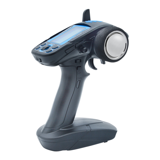
Page 4: Transmitter Overview
TRANSMITTER OVERVIEW Antenna Status LED LCD Display Channel 1 Steering Wheel Roller Button Stopwatch Cruise Control Flashlight Channel 5 (linear output) Power Switch ST D/R Back Button Channel 3 Channel 4 (Control The Forward And Reverse Output) (Left,neutral,right) Battery TH Trim(Channel 2) Channel 6 ST Trim(Channel 1) Flashlight... -
Page 5: Transmitter Battery Installation
TRANSMITTER BATTERY INSTALLATION Before operation, install the battery and connect the system as instructed below. Danger Only use specified batteries (X4 AA batteries). Do not open, disassemble, or attempt to repair the battery. Danger Danger Do not crush/puncture the battery, or short the external contacts. Do not expose to excessive heat or liquids. -
Page 6: Receiver Overview
RECEIVER OVERVIEW Antenna Connectors 1. Steering servo (CH1) 2. Throttle servo (CH2) Switch 3. CH3 servo (CH3) Analog Servo 4. CH4 servo (CH4) 5. CH4 servo (CH5) 6. CH4 servo (CH6) Digital Servo 7. CH4 servo (CH7) RECEIVER CONNECTION Connector motor Connector battery Power switch On-/Off... -
Page 7: Antenna Use
ANTENNA USE Do not point the antenna directly at the model. Never grip the transmitter antenna during operation. It signi cantly degrades the RFsignal quality and strength and may cause loss of Note control. For best signal quality, ensure that receiver is mounted away motors or metal parts. -
Page 8: Connecting The Receiver And Servos
CONNECTING THE RECEIVER AND SERVOS Connect the receiver and the servos as indicated below: Receiver Receiver Make sure to connect in correct direction. Receiver battery case ATTENTION Make sure that male and female connectors have the correct polarity! When connecting servo leads to the receiver always ensure that the yellow lead/wire is facing inwards (towards the crystAal). -
Page 9: Binding The Transmitter And Receiver
OPERATION INSTRUCTIONS After setting up, follow the instructions below to operate the system. POWER ON Follow the steps below to turn on the transmitter: 1. Make sure that: · The battery is fully charged and installed correctly. · The receiver is installed correctly and powered down. 2. -
Page 10: Transmitter Handling
TRANSMITTER HANDLING A. STEERING WHEEL B. THROTTLE TRIGGER Neutral Brake/ Left Right Speed down Neutral Forward/ Speed up Important!!! Should there continue to be no connection between the transmitter and the receiver, a “binding” procedure has to be conducted as well. To do this, please keep in mind the previous point “Connection of the transmitter and receiver”. -
Page 11: Operating Procedure
OPERATING PROCEDURE Many publications say that the setup sequence for the transmitter and receiver don’t play a role anymore with 2.4 GHz sets. However, we recommend sticking to the sequence typical for previous sets. • Before operation: Connect the drive battery to the control unit. First turn on the transmitter, then the receiver. •... - Page 12 1. MOD(MODEL SELECTION) • This transmitter can store 15 sets of models (01-15) to adapt different model products to quickly invoke saved Settings. Feature Set: • Under the boot menu, enter the selection menu by pressing the wheel. a. Press the wheel key again to enter number 01, and then rotate the required model number through the wheel.
- Page 13 4. D/R (DUAL RATE) • DR function is used for adjust the maximum value at both ends of the channel, and to reduce or enlarge at the same rate. Default 100% maximum. Feature Set: • This function is used for adjust the ratio of direction or throttle channel, and the adjustment range is between 0 and 100%.
- Page 14 7. REV (REVERSE DIRECTION) • This function is used for correct the control direction of servo or motor. Feature Set: • This function can set the forward and reverse of 6 channels. • Under the boot menu, enter the selection menu by pressing the scroll wheel.
- Page 15 10. SVC (SMART VEHICLE CONTROL) Note: the smart vehicle control function is only applicable to transmitter and tb-rx200 receiver as a set. • The smart vehicle control function can use for the gyroscope of the receiver to control the direction of the vehicle intelligently, which can guarantee the vehicle to run normally in the expected direction even in the case of road bumps or sharp turns.
- Page 16 12.RST (RESTORE FACTORY SETTING) • Before use this function, it should be cleaning up previous setting, one key to restore factory setting shortcut key, there are two modes to restore factory setting. 1. RST-M only restore the current model. 2. RST-R Restore all Settings. Feature Set:...
- Page 17 14.T/T (TEMPERATURE MODE) • This function is used for measure the temperature of external equipment. functional operation: a. Turn the wheel to the (T/T) menu, enter the menu operation. b. It can measure temperature when the temperature probe touched external equipment. Temperature mode SEC (STOPWATCH FUNCTION) •...
-
Page 18: Specification
SPECIFICATION Transmitter HP-007TX Suitable model vehicle / boat Channel number 2405-2478GHz Frequency range 1MHz Waveband width Waveband number <20dBm Transmit Power GFSK Modulation Mode Channel delay < 20ms/10ms When voltage lower to 4.4v of AA battery; Low-voltage alarming or lower to 7.2v of two Lipo batteries 200mm Antenna length Display... -
Page 19: Notizen / Notes
NOTIZEN / NOTES... - Page 20 Shenzhen Hobby Porter Co.,Ltd. www.hobbyporter.com...
Need help?
Do you have a question about the HP-007 and is the answer not in the manual?
Questions and answers