Table of Contents
Advertisement
Quick Links
Advertisement
Table of Contents

Summary of Contents for Start Shaphon CC-M3
- Page 1 CNC Cutting Controller CC-M3 & CC-M3c Manual Beijing Flourishing Start Control Technology Co., Ltd. 5F Building 2, No.9 Shuangyuan Road, Shijingshan District, Beijing, China 100041 Tel: 0086 10 8890 9235 Mobile (WhatsApp): 0086 159 0106 9532; Email: cuttingcnc@hotmail.com; Skype: henryhaozq...
- Page 2 Catalog Safety Chapter 1 controller general introduction 1-1 Installation dimension 1-2 display 1-3 keys 1-4 USB port 1-5 Switch power supply 1-6 Replays 1-7 Signal ports Chapter 2 parts load 2-1 load from Figures 2-2 load from disk 2-3 load from Edit 2-4 restore parts cutting Chapter 3 parts nest 3-1 rotation...
- Page 3 5-9 save Chapter 6 Edit 6-1 edit function 6-2 code instrument 6-3 coordinate system 6-4 G command 6-5 M assistant function 6-6 file manager Chapter7 Diagnose 7-1 diagnose Appendix 1. Quick user guide...
- Page 4 Safety notice Please carefully read the manual before using the product. Here list some safety operation items, but they can’t replace some safety operation rules from the country and the company. Safety operation Users must follow safety operation rules made by the country and the company. Mechanical dangerousness Operation and repair of automation equipment are a little dangerous and are careful.
- Page 5 The controller has a manual. If the controller damages because of abnormal operation, we are not responsible for maintenance. Controller operation and maintenance Only professional operators can use the controller. Controller operation Please use fingers to press buttons. Please don’t change functions and parameters at random if you are not familiar with them. Please feel free to let us know problems during operation.
- Page 6 Chapter 1 controller general introduction Basic parameters Processor: industrial ARM chip Display: 10.4” color LCD Input/output: 20 optoelectronic isolation input, 20 optoelectronic isolation output Axis number: 2 axes, 4 axes are available AD/DA: DA X 1 Communication: RS232 X 2, USB X 1 Pulse equivalence: electronic gear numerator, denominator set range: 1 ~ 65535 Store space: 4G Installation dimension: 410 X 310 X 58 (mm)
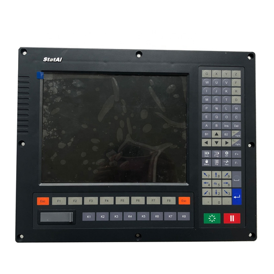
- Page 7 CC-M3C 1-2 Display 10.4” true color LCD, resolution: 640*480 CC-M3 Front panel...
- Page 8 CC-M3c...
- Page 9 1-3 Keys Function keys: specific function is up to the current interface. Esc is to cancel or back to the previous menu. Cursor movement keys: to move the cursor or to move the figure when preview. Letters keys: mainly to edit the program, or to operate in the auto and manual interfaces. Fast operation: 1.
- Page 10 Switches keys: manually turn on or turn off the external switches Directions, speed adjustment, torch up/down keys Up/down, edit, speed adjustment keys torch up/down, or pageup/down when edit. F+: speed up F-: speed down Del: delete Ins: insert Enter: confirm Start, pause keys When preheat, extend delay,...
- Page 11 It’s better that U disk format is FAT and FAT32 format with small storage. It’s better to save the program from the U disk to the controller to cut. CC-M3 USB transfer speed is 20 times as fast as SH-2200H. 1-5 Power switch 1-6 Emergency stop switch After press it, the running motors immediately stop and all output are closed.
- Page 12 Input signal port: 25-pin X 1 Output signal port: 25-pin X 1 Communication signal port: 9-pin X 1, RJ45 internet access X 1 Motor signal port: 9-pin port X 2 Power port: 3-pin plug 1-8 Signal port Output principle diagram...
- Page 13 Input principle diagram Input signal port definition Diagnosis interface can check input port, and change the position of the input port and set the input signal logic. 25-pin port Signal definition Instruction X + limit Connect X axis + limit switch X - limit Connect X axis –...
- Page 14 Pause Connect external pause key Start Connect external start key Z + limit Connect Z axis + limit switch Z - limit Connect Z axis – limit switch Close Connect external general switch Torch collision Connect the lifter collision check switch X 0 point X 0 mechanical origin Y 0 pint...
- Page 15 High preheat Preheat Low oxygen Powder Torch B up Torch height control Torch B down Drill up Drill down Drill on 24V + External DC24V+ 24V + External DC24V+ 24V - External DC24V ground 24V - External DC24V ground Communication signal port CN1 (RJ45) communication port definition Internet access Signal definition...
- Page 16 Driver connection principle diagram of optical coupler (common anode) signal...
- Page 17 Motor signal port definition Motor 1 Port (9-pin) Signal definition Instruction X axis + direction X axis - direction X axis + pulse X axis - pulse Y axis + direction Y axis - direction Y axis + pulse Y axis - pulse Motor 2 Port (9-pin) Signal definition Instruction...
- Page 18 Chapter 2 load parts 2-1 load from figure Turn on CNC, press F6 Figure There are 48 common parts, choose by direction keys and press F8 to confirm. Press direction keys to choose parameters of the part, input values by number keys. F1 Part: set the figure as part.
- Page 19 direction). F3 Rotate: input angle, positive number is anticlockwise, negative number is clockwise. F4 Nest: nest part. F5 Edit: load the part program in the edit area. F6 Run: load the part and enter auto cutting interface. F7 Commit: submit F8 SaveAs: save current part program.
- Page 20 F1 Disk: files in CNC disk. F2 U Disk: files in U disk. F3 View: preview the current file. F4 Search: input file name and search it. F8 OK: load the file. Note: CNC only supports 1-level folder, don’t set folder in the folder. 2.
- Page 21 The difference of two methods is that if cut the part program from the Edit interface, it needs to go to Auto interface. 2-3 load from Edit In the Edit interface edit G code program and save and go to auto cutting interface. F1 New: create a new program edit area.
- Page 22 F3 BreakP (break point): display the file name of the latest breakpoint, (serial number). Controller can record 3 latest break points of 2 files, press F3 again to display last break point till the first break point. The controller automatically loads the file and preview figure and display the break point position. Record rule: a.
- Page 23 After input angle, press Enter, the part is rotated, positive value is anticlockwise, negative value is clockwise. Press F3 again to cancel. 3-2 mirror Press F4 Mirror...
- Page 24 X mirror, Y mirror and XY mirror display in cycle, press Enter to confirm. Press F4 to cancel. 3-3 scale Press F5 Scale...
- Page 25 After input scale value, press Enter to confirm, press F5 to cancel. 3-4 nest Press F6 Nest...
- Page 26 LnNo: the number of line. CoNo: the number of column. Ln Gap: line gap. Co Gap: column gap. Offset: line offset. Note: 1. after set the line offset, the controller automatically limits the nesting width, the actual quantity is smaller than input quantity. 2.
- Page 27 F1 Add: add parts. F2 Delete: delete parts. F3 Ahead: change cutting sequence, a place in advance. F4 Aback: change cutting sequence, a place back. F5 Remove: move the part by direction keys. F7 Refresh: display cutting sequence. F8 Save: save part program. L1 BoardL: plate length L2 BoardW: Plate width L3 Space: gap of parts...
- Page 28 F1 Figure to add parts...
- Page 29 Choose the part and set parameters, press F7 to preview, press F8 to confirm, Note: after revise the number of part, must preview. Press F2 File, dd parts from local disk.
- Page 30 Choose parts and press F8 to confirm and input the number of parts, press Enter. Delete parts After add parts, choose them by direction buttons, press F2 to delete.
- Page 31 Change parts sequence After add parts, change cutting sequence by “Front” and “Back”, press F7 to refresh. Move parts After add parts, choose them by direction buttons, press F5 to move, press L4 to set movement distance.
- Page 32 Rotate parts After choose parts, press L5 and input rotation angle.
- Page 33 Save nesting parts program Press F8 to save.
- Page 34 Chapter 4 cut parts 4-1 Auto interface After turn on controller, press F1 to Auto...
- Page 35 Figure display area After load parts, press F4 to preview, there is part outline size at the left top corner. X: zoom in the figure Y: zoom out the figure G: restore the figure Move the figure by direction buttons. Set figure In Parameter and Figure interfaces figure can be set.
- Page 36 K: turn on and turn off output. SU/SD: torch up/down. Highlight means turn on. L1: set cutting speed limitation L2: set kerf compensation L3: outline mode, press Start, torch will move along the outline to check whether the plate is big enough. L4: simulation run mode, press Start, torch will move along the cutting path till program ends without output.
- Page 37 Speed limitation 1. L1: set cutting speed. 2. Multi-functional knob, turn it to adjust speed rate. 3. F+/F- to adjust. In auto interface, under pending state, press “0” to check and revise “idle-run speed”, “cutting speed”, “manual speed” and “back speed”. Note: the adjusted speed rate will be recorded till adjust next ime.
- Page 38 1. Manual move the torch to any position Press direction buttons to move the torch, release buttons and the torch stops. L3 continue: press direction buttons to move the torch, it stops till press Pause, or the same or reverse direction buttons.
- Page 39 Reset “use 0 point switch” in “Machine” and reset direction in “System” is not 0, press Reset, the axis fast moves along reset direction, and stops when meet mechanical 0 point signal, current coordinate is parameter origin coordinate, machine coordinate clears. “do not use 0 point switch”...
- Page 40 L3 outline, choose it, press start button, torch moves along outer outline to check whether torch is beyond plate. Simulation run Before cutting, choose simulation run to check cutting path is right or not. L4 simulation run, choose it and press start button, torch moves along program path at cutting speed. During the operation, output is invalid.
- Page 41 Change start point For some irregular parts or plate, in order to get cutting start point, can change that point. L5 change start point, current start point displays at left bottom corner in part figure preview area. Press L5 button several times to change that point. Press start button, torch moves to the first pierce point from selected start point and then cut.
- Page 42 After input pierce point number, and confirm to preview selected pierce point position. Display the target point after section. Option dialog displays after start.
- Page 43 CurPLocate (current point location): after confirm, torch makes the current position as pierce point, after start, cut. RefPLocate (reference point location): after confirm, torch locates as reference coordinate and moves to the pierce point in idle-run speed, press start, cut. Choose as program line number: F2 section, press twice, input line number, after confirm, preview the start position of selected line.
- Page 44 After start, controller will work as below, 1, deal with parts cutting program, draw parts preview figure. 2, output and delay time and other movements. 3, control torch up/dwon. 4, port input signal. 5, speed adjustment. 6, refresh figure and state. Dynamic figure display: During cutting, controller dynamically displays current torch position, can zoom preview figure.
- Page 45 items at right side, also can move torch at 10% of manual speed, press F to change between 10% and 80%. Start: After pause, press start button, controller pierce at current position, then continue to cut. Flame cutting, if close preheat, controller finishes pierce; if preheat goes on, then skip preheat, then pierce, so discover preheat state, after enough preheat, then start.
- Page 46 Press start button, torch moves to selected pierce point position from current position. StartPoi (back to the start point): Back to start point after pause. Press L3 after pause, torch moves back to start point in idle-run speed. Simulate (simulation run): After pause to press L4 to simulatively run the left parts program. Move (continuously move): After pause, can manually move torch, the default state is “press to move, release to stop”.
- Page 47 Cut Back: F6 pierce at current position, then cut to pause position by shortest path, choose the operation, please choose path to avoid wrong cutting. Move Part: F7 pierce at current position then cut the left parts. When plate and parts have enough space, or near plate edge, choose “cutting back” , better smoothness of break point.
- Page 48 Chapter 6 Setup Press F4 to enter settings interface Speed Start Speed Start and stop speed Speed Coefficient When reduce or increase speed, change is fast or slow, the bigger, the slower Speed Limit Max. speed when manually or idle-run (G00) Cut Speed Limit Max.
- Page 49 advance Corner Speed Limit Auto mode, max. speed of cutting the corner between two sections Note: when change direction during torch movement, controller will lower speed in advance to avoid torch shake. In fact, torch shake is caused by different factors, such as inertia, machine rigidity and so on, users can set the corner speed to improve steadiness.
- Page 50 Formula: numerator/denominator=lead screw pitch X 1000/(360*subdivision number/step angle* drive ratio) Adjustment method: 1) set a ratio, such as 8/1, manually move a standard distance, such as 2000, measure actual moving distance, use formula, 8*actual distance/1*2000, if the actual distance is 2651, then the simplified fraction is 2651/250. 2) set a ratio, such as 8/1, manually move a standard distance, such as 2000, measure actual moving distance, press F key, input the value, press Enter, there is result, press F8 to confirm.
- Page 51 Note: machine origin can set to any point of value range. Control Metric/British System Length unit, 0: metric system (mm), 1: metric system (in) Coordinate Same as machine direction G41/42 Check Whether check interference caused by kerf compensation Torch Up after Pause Whether torch automatically move up after pause (height is up to torch up time) Edge Pierce Valid: move to pierce point, automatically pause, manually move to proper...
- Page 52 Craft Two cutting types: plasma and flame, F5 Switch key to change. Flame...
- Page 53 Ignition Time Ignition time Preheat Time Preheat time, default is 100s for new program Pierce Time Pierce time at pierce height Move Pierce Time Keep output when pierce and XY axis start to move Torch Up Time Torch up time after cutting Torch Down Time Torch down time after ignition Pierce Up Time...
- Page 54 preheat output, then turn on ignitor output, after ignition, turn off ignitor output, keep gas and low preheat output, preheat starts, after preheat, pierce starts. Don’t use auto ignitor 1, when ignite, ignition time set 0, firstly press K1 to open gas and low preheat output, manually ignite gas 2, when pierce, controller doesn’t open ignitor output, ignition time skip, directly preheat starts Pierce Time: after preheat, torch moves up to pierce position, open cutting oxygen (high oxygen) output, the time of pierce starts...
- Page 55 Plasma...
- Page 56 Torch Up Time Time of torch moving up after cutting Torch Down Time Torch lifter has no location switch (zero point switch), location feedback set 0, torch down time, torch height is arc strike height; when check location feedback, down all the time till zero point Location Up Time When location feedback valid, check location switch signal input, close torch down output, open torch up output, keep location up...
- Page 57 Torch Down Time: torch lifter has no location switch (zero point switch), location feedback set 0, torch down time end, torch height is arc strike height Note: when check location feedback, torch down time invalid Location Up Time: when check location feedback valid, check location switch signal input, close torch down output, open torch up output, keep location feedback and close, torch height is location height (arc strike height) Note: when don’t check location feedback, location up time invalid...
- Page 58 Plasma cutting procedure (with location check and arc strike success check)
- Page 59 Figu (Figure) parameters Pretreat Figure You’d better not choose figure pretreatment for oversized file Kerf Display Cancel kerf line display to simplify figure display Outline Display Cancel outline display to simplify figure display Pierce No. Display Cancel pierce number display to simplify figure display Figure pretreatment: set whether preview figure before cut, when file is over 1M, can choose don’t pretreat figure to save time Note: no effect on cutting path display...
- Page 60 Pneumatic Lifting 1 use, 0 don’t use. When use, arc strike and pierce keep torch down output during cutting Zero Point Switch 1 use, 0 don’t use. Moving method when manual reset Circle The First Arc Set small circle 1 speed limitation, diameter ≤...
- Page 61 To Default All parameters become default Save As Default Save all parameters as default Lead out Parameter Create parameter file in SD card, expanded name “PAG”, existed parameter file will be replaced, please backup Lead in Parameter Lead in parameter file in SD card to replace all parameters, if from U disk, firstly by manager, save all parameter file in SD card Parameter Set parameter revise permission...
- Page 62 L: Cycle times or delay time X: X axis absolute coordinate Y: Y axis absolute coordinate U: distance of X axis relative points V: distance of Y axis relative points I: When cutting arc, the value of the coordinate of the circle centre subtract X axis start point value J: When cutting arc, the value of the coordinate of the circle centre subtract Y axis start point value R: Specified arc radius H: Chord height of the arc...
- Page 63 G90 // absolute coordinate, default G00 X100 Y100 // rapidly locate to (100, 100) G01 X600 Y200 // straight line to (600, 200) 3) G20/G21 British system/ metric system instruction G20 British system, X, Y, I, J, R, U, V, H, F, behind G20, all are British system unit G21 Metric system (default), X, Y, I, J, R, U, V, H, F, behind G21, all is metric system unit Format: G20 Format: G21...
- Page 64 ● current torch position ○ torch expectant position 6) G02/G03 arc cut This command is for arc interpolation, clockwise arc G02, anticlockwise arc G03, Format: G02[03] X[U]n Y[V]n In Jn [Fn] or G02[03] X[U]n Y[V]n In Rn [Fn] G02[03] PPn In Kn [Fn] or G02[03] PPn Rn [Fn] e.g.
- Page 65 R is the radius of the circle (R is positive value, when arc <=180 degree, R is radius) If I、J are specified, don’t use R; vice versa 7) G04 pause / delay command This command is to set up delay, when program run to this command, program will be delayed as L specified time, unit is second Format: G04 Ln e.g.: G04 L2.4 (delay 2.4 s)
- Page 66 6-5 M assistant function M00: program pause command, press [Start] to continue M02: program end command, program is in the state of wait M30: same as M02 M10/M11: gas (acetylene) valve switch, M10 (on), M11 (off) M12/M13: cut oxygen valve switch, M12 (on), M13 (off) M14/M15: torch up switch, M14 (on), M15 (off) M16/M17: torch down switch, M16 (on), M17 (off) M24/M25: preheat switch, M24 (on), M25 (off)
- Page 67 3, torch down (M73), plasma has no this movement 4, Turn on the torch height controller (M38) M52 ignition fixed cycle Turn on gas (acetylene) valve (M10), turn on high voltage ignition (M20), delay ignition, turn off high voltage ignition (M21) M70 torch up fixed cycle It’s used for the start and the end of a program, torch up, to make torch move to another position.
- Page 68 F1 Disk (local disk), display local disk directory F2 U disk, display U disk directory F3 View (preview), display current part figure F4 Search, search file as file name F5 New, build file folder F6 Copy, copy file to U disk and local disk F8 OK, confirm input or choose Enter key: choose current file Del: delete current file...
- Page 69 1, U disk format is FAT32 2 can copy and delete several files at the same after select 3, there is operation tip when cursor moves to file folder F4 search parts Input file name to search F5 New, input file folder name to build Chapter 7 Diagnose Main menu press F5 Diagn (diagnose) 7-1 diagnose...
- Page 70 F1 Input, display input state F2 Output, display output state F7 State, set current port state logic F8 Save, save current port state logic Input Display current input port level high/low, can set current level high/low and logic, logic has “Yes”, “No” and “disable”.
- Page 71 F5 Reverse, change output port level high/low. Adjust moving precision Start ---> parameter-system (numerator:2, denominator: 1) ---> manual-point move-increment:100 ---> move-direction buttons-measure actual moving distance ---> parameter-system-calculation-input actual distance-press Enter, numerator & denominator change-save parameters ---> manual-point move verification ---> right or not ---> yes ---> end. Controller upgrade Start --->...
Need help?
Do you have a question about the CC-M3 and is the answer not in the manual?
Questions and answers
hi good day my cnc plasma measure to mutch on x and y axes..... can you help
To adjust the X and Y axes measurement on a Start Shaphon CC-M3 CNC plasma, follow these steps:
1. Turn on the CNC system.
2. Reset the machine coordinates:
- If "do not use 0 point switch" is enabled in the "Machine" settings, press Reset to clear accumulated coordinates.
- If using 0 point switches, both axes reset simultaneously, stopping when one axis reaches the 0 point switch, then the other continues.
3. Manually align parts (plate calibration):
- Press direction buttons to move the torch and align one side of the plate.
- Press F4 to set the start point.
- Move the torch to align another point on the same side.
4. Define movement signals for X and Y axes:
- X-axis dual-drive signals:
- XD+ (direction +)
- XD- (direction -)
- XC+ (pulse +)
- XC- (pulse -)
- Y-axis dual-drive signals:
- YD+ (direction +)
- YD- (direction -)
- YC+ (pulse +)
- YC- (pulse -)
5. Adjust parameters using F6 and F8:
- Press F6 to enter the figure selection menu.
- Use direction keys to choose parameters and press F8 to confirm.
- Input values using number keys as needed.
These steps allow you to calibrate and adjust X and Y axes measurements effectively.
This answer is automatically generated