Table of Contents
Advertisement
Quick Links
Advertisement
Table of Contents

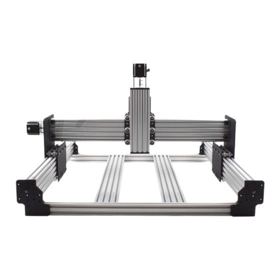
Summary of Contents for OOOZNEST WorkBee CNC
- Page 1 Mechanical Assembly Instructions Screw Driven...
-
Page 2: Table Of Contents
2.7 Spoiler Board Support Extrusions - Method 2 ............ 34 2.7.2 Spoiler Board Support Brackets ............35 2.7.3 Spoiler Board Support Assembly ............36 2.7.4 Attaching Spoiler Board Supports ............37 2.8 Complete ...................... 38 3.0 Appendix ......................39 3.1 Appendix A - Kit Contents ................39 WorkBee CNC... -
Page 3: Getting Started
1.0 Getting Started 1.1 About The Kit The WorkBee CNC is an open source design designed and introduced by OOOZNEST and is an offspring of the OX CNC Machine designed by Mark Carew of Open Builds 1.2 Check Product Contents The first thing you should do when you receive your kit is to check the contents against the list in Appendix A. - Page 4 The WorkBee CNC Machine and this instruction manual are derived directly from the Open Source versions published by Ooznest. Credit is due to the Ooznest team for their work on the WorkBee.
-
Page 5: Assembly
2.0 Assembly 2.1 Wheel Assembly 2.1.1 Solid V Xtreme Wheel Assembly From the Solid-V-Wheel-Xtreme-Kit packet, with a Precision-Shim in between, insert a 625-2RS- Bearing into either side of the Solid-V-Wheel-Xtreme. Repeat this for 48 Solid-V-Wheel-Xtreme-Kits. WorkBee CNC... -
Page 6: Y-Plate Assembly
Thread a Y-ACME-Lead-Screw through both ACME-Nut-Blocks. Tighten the bolts holding one of the ACME-Nut-Blocks, making sure it is square to the Y-Plate-Left. To remove any backlash, pinch the loose ACME-Nut-Block towards the previous one, and tighten the bolts holding it. Leave the Y- ACME-Lead-Screw threaded through the ACME-Nut-Blocks. WorkBee CNC... -
Page 7: Y Wheels & Y-Plate-Inner
Aluminium-Spacer-6mms. Starting with an outside pair of wheels, adjust both Eccentric-Spacer-6mms down onto the C-Beam Extrusion until there is a small amount of friction between both wheels and the C-Beam Extrusion. When adjusting the pair of Eccentric-Spacer- WorkBee CNC... - Page 8 Slide the C-Beam extrusion back and forth through the wheels. This should require a small amount of force, and all wheels should spin as it rolls. Also check there is no wobbling of the extrusion. Once happy, double check the tightness of the M5-NylonNuts. WorkBee CNC...
-
Page 9: Stepper Motor
Attach the NEMA23-Stepper-Motor to the threaded holes on the Y-Plate-Left using 4 x M5-Low- Profile-50mm bolts and 4 x Aluminium-Spacer-40mm’s. Orient the NEMA23-Stepper-Motor so that the wire is towards the back of the Y-Plate-Left (the side closet to the small rectangle opening). WorkBee CNC... -
Page 10: Repeat
2.2.4 Repeat A. Except from Section 2.2.3, repeat the rest for Section 2.2 for the Y-Plate-Right. As seen above it should be a mirror image of the Y-Plate-Left-Assembly apart from the stepper motor. WorkBee CNC... -
Page 11: X-Carriage Assembly
Aluminium-Spacer-6mms. Starting with an outside wheel, adjust the Eccentric-Spacer-6mm down onto the C-Beam Extrusion until there is a small amount of friction between the wheel and the C-Beam Extrusion. Repeat this for the other outside wheel, and then for the middle wheel. WorkBee CNC... - Page 12 Slide the C-Beam extrusion back and forth through the wheels. This should require a small amount of force, and all wheels should spin as it rolls. Also check there is no wobbling of the extrusion. Once happy, double check the tightness of the M5-Nylon-Nuts. WorkBee CNC...
-
Page 13: Z Acme Nut Block
With the set screw provided with the ACME-AB-Nut-Block, screw it into the smaller threaded hole on the top until it is just before the point of touching the surface on the opposite side of the gap. The set screw will later be used to remove any back lash from the system. WorkBee CNC... -
Page 14: Acme Nut Blocks
Thread the X-ACME-Lead-Screw through both ACME-Nut-Blocks. Tighten the bolts holding one of the ACME-Nut-Blocks, making sure it is square to the X-Plate-Back. To remove any backlash, pinch the loose ACME-Nut-Block towards the previous one, and tighten the bolts holding it. Leave the X- ACME-Lead-Screw threaded through the ACME-Nut-Blocks. WorkBee CNC... -
Page 15: Wheels & X-Plate-Front
Run any piece of C-Beam extrusion in between the two rows of wheels. Initially, the C-Beam will wobble between the wheels. Turn the assembly upside down so the C-Beam is sitting on the row WorkBee CNC... - Page 16 Slide the C-Beam extrusion back and forth through the wheels. This should require a small amount of force, and all wheels should spin as it rolls. Also check there is no wobbling of the extrusion. Once happy, double check the tightness of the M5-NylonNuts. WorkBee CNC...
-
Page 17: Z Mating
Low-Profile-20mm bolts and 8 x M5-Nylon-Nuts to secure the two assemblies together. Make sure the Z-Plate-Assembly is square to the X-Carriage-Assembly. The Allen key can be inserted through access holes on the X-Plate-Back to gain access to the bolt heads. WorkBee CNC... -
Page 18: Z Extrusion
A. Slide the C-Beam-250mm through the Z-Wheels on the X-Carriage-Assembly. Attach the Z-End- Mount-Motor and Z-End-Mount-Bottom using 8 x M5-Low-Profile-15mm bolts. Tighten the Z-End- Mount-Motor bolts fully. For the Z-End-Mount-Bottom, tighten the bolts fully, and then loosen by a single full turn (the reason for this will become clear later). WorkBee CNC... -
Page 19: Z Stepper Motor
NEMA23-Stepper-Motor. Don’t tighten it down at this point. Attach the NEMA23-Stepper-Motor to the threaded holes on the Z-End-Mount-Motor using 4 x M5- Low-Profile-50mm bolts and 4 x Aluminium-Spacer-40mm’s. Orient the NEMA23-Stepper-Motor so that the wire is towards the back of the X-Carriage-Assembly. WorkBee CNC... -
Page 20: Z Acme Screw
In Section 2.3.6 Step A, locate the four M5-Low-Profile-15mm bolts that were left a full turn from tight. These can now be fully tightened. Doing this will remove any play that may be present from Step D & E in this section. WorkBee CNC... - Page 21 Do not over tighten this, as it can make the ZACME-Screw difficult to turn. You can test this by rotating the Flexible-Coupler by hand. It should require a small to medium amount of force. This will need to be rechecked once the router is attached, and periodically checked when in use. WorkBee CNC...
-
Page 22: X-Gantry Assembly
Attach the C-Beam-1500mm to the four non-threaded holes on the Y-Plate-Right-Assembly shown above using 4 x M5-Low-Profile-15mm bolts. Loosen the M5-Low-Profile-15mm bolts on the Y-Plate-Left-Assembly by a single full turn (the reason for this will become clear later). WorkBee CNC... -
Page 23: X-Carriage & Y-Plate-Left Assembly
Slide the X-Carriage-Assembly onto the C-Beam-1500mm in the orientation seen above. Repeat Section 2.4.3 for the Y-Plate-Left-Assembly, but do not loosen the M5-LowProfile-15mm bolts this time. Recheck the bottom Eccentric-Spacer-6mms on the X-Carriage-Assembly to make sure they are touching the rail and that there is no wobble. WorkBee CNC... -
Page 24: Acme Screw
Doing this will remove any play that may be present from Step B in this section. While doing this also place the X-Gantry-Assembly on a flat table, and check that it is flat and square. If it isn’t, undo some of the M5 Low-Profile-15mm bolts and adjust it. WorkBee CNC... -
Page 25: Angle Corners
1500mm. A M5-Low-Profile-8mm screws into the Tee-Nut previously inserted, and a M5-Low- Profile-15mm goes though the Angle-Corner and attaches to a M5-Nylon-Nut on the outside of the Y-Plate-Right-Assembly. Repeat Step A for the other 3 Angle-Corners in the positions shown above. WorkBee CNC... -
Page 26: Base Assembly
Slide a C-Beam-1500mm through each set of wheels on the X-Gantry-Assembly. The YACME- Screws go inside the ‘C’ Channel. Rest the ends of the C-Beam-1500mm on 2 x V-Slot-2040-1495mm’s. The ends of the extrusions should be flush with the sides of each other. WorkBee CNC... -
Page 27: End Plates
Square the base, and repeat Steps B, C,D, & E for the back V-Slot-2040-1495mm. Loosen the M5-Low-Profile-15mm/12mm bolts on the front Y-End-Plate-Left & Y-End Plate-Right by a single full turn (the reason for this will become clear later). WorkBee CNC... -
Page 28: Stepper Motors
4 x M5-Low-Profile-50mm bolts and 4 x Aluminium-Spacer-40mms. Orient the NEMA23-Stepper-Motor so the wire is facing downwards. Repeat Steps A & B for the final NEMA23-Stepper-Motor attaching it to the Y-End Plate-Left on the back right of the machine (as if looking from the front). WorkBee CNC... -
Page 29: Y Acme Screws
Doing this will remove any play that may be present from Step B & C in this section. If possible, get a second person to hold the base square while tightening the bolts. WorkBee CNC... -
Page 30: End Caps
2.5.5 End Caps Attach an End-Cap to front left end of the V-Slot-2040-1495mm using 2 x M5-Low-Profile-8mm bolts. Repeat this for the other 3 x End-Caps on the other bare ends of the V-Slot-2040-1495mms. WorkBee CNC... -
Page 31: Spoiler Board Support Extrusions - Method 1
6 x Tee-Nuts for a 1000mm X-Axis, and 8 x Tee Nuts for a 1500mm X-Axis. Insert the V-Slot-2040-1415mm in between both C-Beam-1500mm’s so it sits on top of the front V-Slot-2040-1495mm. The outward face should be against the Y-End-Plates. Repeat Steps A, B & C for the back V-Slot-2040-1415mm. WorkBee CNC... -
Page 32: Y-End-Plate Final Bolts & Angle Corners
Section 2.6.1 Step A. Secure the Angle-Corner tightly in the corner between the C-Beam-1500mm and V-Slot-2040-1415mm while the machine is held square. Repeat Step B for the other 3 corner joints between the C-Beam-1500mm and V-Slot2040- 1415mm rails. WorkBee CNC... -
Page 33: Spoiler Board Support Brackets
3 more Universal-Bracket-Triples need to be attached to the V-Slot-2080-1460mm as shown above, repeating Steps A & B. If you have a machine with a 1500mm X-Axis repeat Steps A, B, & C for one more VSlot-2080- 1460mm. 2 more times for a 1000mm X-Axis. WorkBee CNC... -
Page 34: Attaching Spoiler Board Supports
2080-1460mm’s with the center marks made in Step B. Line up all the previously inserted Tee-Nuts in Step A and in Section 2.6.1 Step B with the holes on the Universal-L-Brackets-Triple’s and secure the Spoilerboard-Support-Assembly using 12 x M5-Low-Profile-8mm’s on each Spoilerboard-Support-Assembly. WorkBee CNC... -
Page 35: Spoiler Board Support Extrusions - Method 2
1495mm using a M5-Low-Profile-8mm bolt and a Tee-Nut that can be inserted from the end of the V-Slot-2040-1495mm. Secure the Angle-Corner tightly in the corner between the C-Beam- 1500mm and V-Slot-2040-1415mm while the machine is held square. Repeat Step B for the other 3 corner joints between the C-Beam-1500mm and V-Slot2040- 1495mm rails. WorkBee CNC... -
Page 36: Spoiler Board Support Brackets
If you have a machine with a 1500mm X-Axis, repeat Steps A & B so there is 2 Universal-L- Bracket-Triples front and back, at 209mm spacing. 3 x Universal-L-Bracket-Triples front and back, at 219mm spacing for a 1000mm X-Axis. WorkBee CNC... -
Page 37: Spoiler Board Support Assembly
Y-Axis larger than the X-Axis, the 22.5mm spacing can be ignored, just center the V-Slot-2040-1415mm. Repeat Step A - D for the other V-Slot-2040-665mm and V-Slot-2080-1460mm. This sections only needs to be carried out twice for all X-Axis sizes. WorkBee CNC... -
Page 38: Attaching Spoiler Board Supports
Spoiler-Board-Support-Assemblies. If you have an X-Axis with a 1500mm X-Axis, the assemblies in section 2.7.3 will take up all Universal-L-Bracket-Triple sets. For a 1000mm X-Axis there will be one set left empty, attach the left over V-Slot-2080 to this set. WorkBee CNC... -
Page 39: Complete
2.8 Complete Congratulations! You have completed the mechanical assembly of the WorkBee CNC. We hope you have enjoyed the build and will continue to bring your WorkBee to life! WorkBee CNC... -
Page 40: Appendix
Y Axis ACME Lead Screw – 781mm Low Profile Screw – 60mm Z Axis ACME Lead Screw – 281mm Drop-in T-Nut – M5 Anti-Backlash Nut Block ACME Nut Block ELECTRONICS 688zz bearing NEMA23 Stepper Motor – 1.26N.m 6.35x8mm Flexible Coupling WorkBee CNC...
Need help?
Do you have a question about the WorkBee CNC and is the answer not in the manual?
Questions and answers