Table of Contents
Advertisement
Attachment Assembly Instructions
Item #
MS90
MFH15
DB44
SB60
BM13
MRH35
DR30
BD23
TSO58
GP58
RS58
HA14
LCA9
LW228
LW16
RK26
BS40
HFH15
HRH35
PP35
FW15
AM39
ROPS20
D1060/UG
BR50
BK45
BK44
BF22
HE47
B612/B616
BD7
RT24
SB18
TR23
BB60
© Copyright 2018 by Struck Corp. Patents pending - MAGNATRAC® is a registered trademark of the Struck Corp
MAGNATRAC
Table of Contents
Manual Rear Hitch Kit
Grouser Plate Kit
Manual Winch Kit
Hydraulic Front Hitch Kit
Hydraulic Rear Hitch Kit
Angle Mount Kit
Roll-over Protective Structure Kit
Backhoe Kits
Material Bucket Kit- Hydro Dump Kit (HFH15 only)
Material Bucket Kit - Manual Dump Kit (HFH15 only)
Bucket Forks Kit - (BK44, BK45 only)
Rock/Debris Thumb Kit (D1060/D1065 only)
Stone Boat Kit (Nose & Chain)
Tripple Shank Ripper Kit
BM1
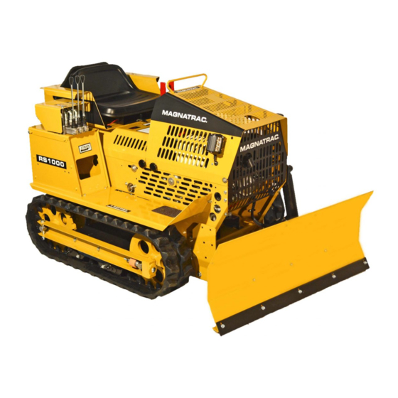
RS1000
®
Version: 4.1.18
Page #
BM3
BM6
BM16
BM18
BM20
BM24
BM28
BM30
BM31
BM32
BM33
BM34
BM35
BM36
BM37
BM38
BM42
BM45
BM48
BM51
BM63
BM65
BM67
BM71
BM94
BM96
BM101
BM104
BM105
BM107
BM108
BM109
BM111
BM113
BM114
.
Advertisement
Table of Contents

Related Manuals for Struck MAGNATRAC RS1000


Summary of Contents for Struck MAGNATRAC RS1000
- Page 1 Rock/Debris Thumb Kit (D1060/D1065 only) BM109 SB18 Stone Boat Kit (Nose & Chain) BM111 TR23 Tripple Shank Ripper Kit BM113 BB60 Ballast Box Kit BM114 © Copyright 2018 by Struck Corp. Patents pending - MAGNATRAC® is a registered trademark of the Struck Corp...
- Page 2 BEFORE YOU BEGIN YOUR ASSEMBLY..a few important facts should be brought to your attention: A) References of left & right are determined by standing behind your Crawler and looking forward. B) Though the following instructions are inclusive, some of the Steps have already been completed at the factory...just go on if you find a particular step has already been completed for you.
-
Page 3: Hh 5/16-18 Spin Lock
Mud Scraper Kit MS90 Fastener & Parts List 001740R Mud Scraper, right 5/16-18x1-1/2 Spin Lock Bolt 001740L Mud Scraper, left 5/16-18 Spin Lock Nut 001759 Tube 3/8-16x1-1/2 Spin Lock Bolt 002005sfp Washer, 3/8IDx1OD (32) 3/8-16 Spin Lock Nut Pre-Assembly: Before beginning actual assembly, loosely assemble the Right and Left Mud Scrapers as shown in Photo below... - Page 4 NOTE: The following instructions will show you in detail how to mount your #1740L Left Mud Scraper. When completed, you will be asked to repeat Fully remove these two the similar assembly for the #1740R Bolts inside Right Mud Scraper. Body.
- Page 5 STEP 4. Slip #1759 Tubes into 1740L 7/8” slots in outside face of #1740L Mud Left Mud Scraper Scraper. Align Tubes with mating Assembly “lower” 3/8” holes on inside face of #1691 Expander. [See Photo bottom of page above] From outside, insert a YY Bolt into each YY Bolts of the aligned Tubes.
- Page 6 Manual Front Hitch Kit MFH15 Parts & Fastener List 001654 Latch Plate 5/16-18 Spin Lock Nut 001665 Handle 001666 Lift Linkage 3/8-16x1-1/2 Carriage Bolt 001667 Arm Latch 3/8-16 Dot Lock Nut 001704sfp 3/8-16x1 Carriage Bolt 001694 Front Hitch 3/8-16x1-1/2 Bolt 001701 Bushing, 1/2IDx3/4OD 3/8-16x2-1/2 Carriage Bolt...
- Page 7 CAUTION The #2203 Springs used in this assembly are common Left “extension springs”. Their assembly re- Body quires that the assembler wears gloves Wall and has sufficient arm strength to pull HH Nuts on the Spring with approximately 30 lbs. Right of vertical force.
- Page 8 2209 STEP 3. From above, insert #1665 Handle into slot in #1605 Right Fender... see Photo at right. 1665 Slip #2209 Grip over #1665 Han- dle on right side of Body... see Photo at right. 1665 “slot” 1605 Right Fender STEP 4.
- Page 9 STEP 6. Remove #Q Bolt and 1665 Remove Q Bolt #HH Nut from location in lower center of and HH Nut from Right Wall... see Photo at right. 1811 this location. STEP 7. In the following order: Insert #AD Bolt into #2005 Washer, 2005 #2207 Bushing, 5/8”...
- Page 10 STEP 11. Following Photo below, slip For BM13 Bucket Mouth use: Slip (2) #1654 Latch Plate around #1665 Handle... se- #2203 Springs over each end of #1670 Pin. For cure with two (2) #I Bolts and #NN Nuts... finger DB44 Dozer Blade use: Slip (1) #2203 Spring tight.
- Page 11 STEP 13. Pull #1665 Handle fully rearward and secure it behind rear “tab” of its #1654 Latch Plate... see Photo at right. STEP 14. With “gloved” hands, rotate each #2203 Spring rearward and loop the top loop of each Spring over the head of its appropriate #AO Bolt...
- Page 12 STEP 17. Following the instruc- DB44 tions closely, completely assemble your Dozer DB44 Dozer Blade. Blade When completed, slip DB44 4121 Dozer Blade’s “Top Mount and Bottom Mount” around #1694 Front Hitch. Bolts Mount & MM Nuts Align 1/2” holes in Top & Bottom Mounts with mating 1/2”...
- Page 13 STEP 20. Totally remove #1654 Latch Plate. Invert it and turn it “end to end”. Remount it per Photo at right... use orignal #I Bolts & #NN Nuts... tighten... see Photo at right. Cross Shaft “resting on” Grill Slip 5/8” hole end of #1666 Lift Linkage off Lower Stud...
- Page 14 1665 KK Nut 1654 “upper” 1667 Arm Latch “locked position” Upper Stud Lower NOTE: The MFH15 Manual Stud KK Nut Front Hitch has (2) different height settings. For dozing appli- cations, use the “upper stud”. For carrying large loads use the “lower stud”.
- Page 15 STEP 24. On top front face of #1606 Left Fender, locate a point 29-1/2” forward of rear edge and 7/8” inward of left edge... see Photos below. At this point, accurately drill a 5/16” hole if it has not already been provided. Locate 5/16”...
- Page 16 Dozer Blade Kit Version: 04.16 DB44 Parts & Fastener List 004118 Blade, 42” wide 004119 Edge, 42” wide 004120 Bottom Blade Mount 004121 Top Blade Mount 5/16-18x1 Spin Lock Bolt 5/16-18 Spin Lock Nut 4118 4119 4121 4120 BM16...
- Page 17 STEP 1. Locate the five (5) 4118 5/16” slots in #4119 Edge with mating five 5/16” holes in lower edge of #4118 Blade. From the front, slip a #R Bolt into R Bolts (5) each of these mating five slots & holes. STEP 2.
- Page 18 Snow Blade Kit SB60 Parts & Fastener List 004164 Blade, 60” wide 004165 Edge, 60” wide 004170 Bottom Blade Mount 004171 Top Blade Mount 5/16-18x1 Spin Lock Bolt (10) 5/16-18 Spin Lock Nut (10) 4164 4165 4171 4170 BM18...
- Page 19 STEP 1. Locate the five (5) 4164 5/16” slots in #4165 Edge with mating five 5/16” holes in lower edge of #4118 Blade. From the front, slip a #R Bolt into R Bolts (5) each of these mating five slots & holes. STEP 2.
-
Page 20: R 5/16-18X1 Spin Lock
Bucket Mouth Kit BM13 Note: Item has been engineered to be used with the MFH15 - Manual Front Hitch sys- tem only. Not to be used with hydraulic attachments. Damage may result & warranty may be voided if used with hydraulic attachments. Parts and Fastener List 001168 Hitch Pin, #8... - Page 21 4105 4119 M Bolts STEP 1. Invert #4105 Bucket Bottom. Locate #4119 Edge over forward edge of Bucket Bottom. Align the five (5) 5/16” wide slots in Edge with mating five (5) 5/16” holes in Bucket Bottom. Insert a #M Bolt in each set of 5/16” holes and slots. Secure inside with #HH Nuts. Push Edge evenly to the rear...
- Page 22 4107 5/16” hole used 4106L STEP 4. Per Photo at right, align Left R Bolt Bracket the two (2) 5/16” holes of #4106L Left & HH Nut Bracket with mating holes in top left 4118 front of #4118 Blade. Insert #R Bolt into Blade each pair of mating holes and secure behind with HH Nuts...
- Page 23 1168 STEP 6. 2232 When both #4107 Locks are fully closed, secure each with a #1168 Hitch Pin... inset Photo at far 2209 right. 4107 STEP 7. Your installation of the 2232 #2232 Handle is strictly “operator pref- 4106L erence”. It is installed to the outside Left surface of the left wall of the #4140 Side Bracket...
-
Page 24: Jj 3/8-16 Spin Lock
Rear Hitch Kit MRH35 Parts & Fastener List 000126 Pin, attachment 3/8-16x1 Spin Lock Bolt 001172 Lynch Pin 3/8-16x1-1/2 Bolt 004130 Hitch Channel 3/8 Washer 001693 Bail 3/8-16 Spin Lock Nut 001701sfp Bushing, 1/2IDx3/4OD 3/8-16 Nylon Lock Nut 004132 Handle 001906 Cotter Pin, 1/8x1-1/4”... - Page 25 STEP 1. Align the six (6) 3/8” Holes in #4130 Hitch with mating six (6) 3/8” Holes in rear surface of #1601 4130 Body Pan. Hitch 1601 1680 “tab” Body From outside, insert a #AH Bolt into each of the six 3/8” holes aligned above.
- Page 26 STEP 5. Per Photo at right, in- 4130 sert end of #4132 Handle into two (2) Hitch 1906 Cotter Pin parallel 7/8” holes in top of #4130 Hitch Channel Channel. Secure left end of Handle with two (2) #1906 Cotter Pins on left and 2579 Washers 4132 Handle right face of Left Channel “side”...
- Page 27 STEP 7. With #4132 Handle ro- 4132 tated fully forward, insert “opened” Handle #1172 Lynch Pin into aligned 3/8” hole “arm” in #413 Handle “arm” and #4131 Link... 1172 close Lynch Pin... see Photo at right. Lynch NOTE: #1172 Lynch Pin is used as a “safety device”...
- Page 28 Double Ripper Kit DR30 Note! Item is recomended for the MRH35 Manual Rear Hitch. TR23 Tripple Rip- per can be used on the MRH35 Manual Rear Hitch as well. The DR30 Dou- ble Ripper is not designed for the HRH35 Hydro Rear Hitch. Parts &...
- Page 29 STEP 1. From outside, screw your two (2) #AI Bolts into 5/8” Nuts welded inside #1693 Bail “channel”... leave approximately 3/4” of each Bolt 1172 exposed... see Photo at right. Lynch STEP 2. Slip #4110 Channel around #1693 Bail “channel”... align 5/8” holes in #4110 Channel with mating “tube”...
- Page 30 Drawbar Kit BD23 Parts & Fastener List 002330 Drawbar 3/8-16x1 Spin Lock Bolt 3/8-16 Spin Lock Nut NOTE: depending on your use, the #2330 Drawbar is able to be mounted in a low position [5-1/2” above ground 2330 Drawbar level] or a high position [9-1/2” above ground level].
- Page 31 Grouser Track Shoe Kit TSO58 Parts & Fastener List 001161sfp Grouser Shoe (58) 5/16-18x3/4 Spin Lock Bolt (174) 5/16-18 Spin Lock Nut (174) NOTE: To clarify the assembly proce- dure, the following Photos show the Grouser Track Shoe being installed on the rear end of the Track.
- Page 32 Grouser Plate Track Shoe Kit GP58 Parts & Fastener List 001705sfp Grouser Plate (58) 5/16-18x1 Spin Lock Bolt (174) 5/16-18 Spin Lock Nut (174) NOTE: To clarify the assembly proce- 1705 dure, the following Photos show the Grouser Grouser Plate being installed on the Plate rear end of the Track.
- Page 33 Rubber Track Shoe Kit RS58 Parts & Fastener List 001641sfp Channel (58) 001642 Rubber Shoe (58) 5/16-18x1 1/4 Carriage Bolt (174) 5/16-18 Spin Lock Nut (174) 1641 Channel 1642 Rubber Shoe NOTE: To clarify the assembly procedure, the following Photos show the Rubber Track Shoe being installed on the rear end of the Track.
- Page 34 Hitch Adapter Kit HA14 Parts & Fastener List 001750 Receiver Assembly [Class #2 opening] (1) NOTE: AF Bolts and AK Nuts described and shown below are provided with your MRH35 or HRH35Rear Hitch Kit. STEP 1. Slip “channel” portion of #1750 1750 Receiver “tube”...
- Page 35 Log Crane Adaptor/Drawbar Kit LCA9 Parts & Fastener List 001708 Adaptor, Drawbar NOTE: 1. AF Bolts and AK Nuts described and shown below are provided with your MRH35 Manual Rear Hitch or HRH35 Hydro Rear Hitch Kit. 2. AH Bolts and JJ Nuts described and shown below are provided with the LW228 Kit.
- Page 36 Log Crane/Drawbar Kit LW228 Parts & Fastener List 002270 Crane Assembly 3/8-16x1 Spin Lock Bolt 3/8-16 Spin Lock Nut LW228 Log Crane/Drawbar Assembly Mounting Plate AH Bolt (4) & JJ Nut (4) STEP 1. Align the pattern of four (4) 3/8” holes in #LW228 Log Crane/Drawbar Assembly with mating 3/8”...
- Page 37 Log Winch Kit LW16 Parts & Fastener List 000160 Hand Winch 000161 Cable & Hook 3/8-16x1 Spin Lock Bolt 3/8-16 Spin Lock Nut LW228 Log Crane/Drawbar Assembly Hand Winch Optional LW16 Manual Winch Kit 161 Cable & Hook Mount your Hand Winch per instructions furnished by Winch manufacturer.
- Page 38 Rake Kit RK26 Note! Item is to be used as a rake, not a ripper. For ripping applications, please use DR30 or TR23. Major damage to attachment can be created by using this attachment for any other purpose other than raking. Parts &...
- Page 39 1172 Lynch STEP 1. From outside, screw your two (2) #AI Bolts into 5/8” Nuts welded inside #1693 Bail “channel”... leave approximately 9/16” of each Bolt exposed... see Photo at right. “tube” AI Bolt 9/16” above surface of 1693 Bail “channel” 1693 Bail “channel”...
- Page 40 126 Pin 2261 Arm STEP 3. Mount and secure with AN Bolts & MM Nuts a #2261 Arm on outside face of each ear of #2260 Yoke... leave Nuts loose. 2260 STEP 4. Slip each “tab” of Yoke #2262 Channel around the mating out- side face of each #2261 Arm.
- Page 41 2263 Angle 1172 Lynch STEP 7. Cover rear of your “rake assembly” with #2263 Angle. Align two (2) 3/8” slots in #2263 Angle with mating top two 3/8” holes in #2262 Channel. Secure with #AH Bolts and #JJ Nuts... tighten... see Photo at AH Bolt right.
-
Page 42: Bottom Blade
Box Scraper Kit BS40 Parts & Fastener List 004103 Box Scraper Assembly 5/16-18x1 Spin Lock Bolt 5/16-18 Spin Lock Nut 4103 Box Scraper Assembly STEP 1. Remove #4119 Edge from Dozer Blade Assembly... save #4120 Bottom Blade Mount, #R Bolts and HH Nuts for reassembly later... see Photo below and next page. Dozer Blade Assembly 4119 Edge BM42... - Page 43 STEP 2. Turn #4103 Box Scraper Assembly “face down”. Lower Dozer Blade Assem- bly “face down” into the Box Scraper Assembly... align five (5) 3/8” slots in “lower edge” of Box Scraper Assembly with mating five (5) 3/8” holes in “lower edge” of Dozer Blade Assem- bly.
- Page 44 Notice angle is in front of the blade. Dozer Blade Box Scraper BM44...
- Page 45 Hydro Front Hitch Kit HFH15 Note: Your HFH15 - Hydro Front Hitch Kit will be factory assembled. These kit instruc- tions are for customers buying a HFH15 at a later date. Assemble your PP35 Power Pack before installing your HFH15 Hydro Front Hitch Kit. Kit Assembly Note: To properly install your HFH15 Hydraulic Front Hitch Kit, begin by completing STEPS 1 thru 4 below.
- Page 46 1694 1661 Brackets 2336 come with RS1000, not the 1707 HFH15. 1701 Major components of HFH15 Hydro Hitch Kit Left NOTE: The following STEPS 1 [right] Body may have been completed at the Fac- Wall tory, if so continue by going to STEP2. HH Nuts Right Body...
- Page 47 STEP 3. Inside, slip a #1701 1661 Bushing over end of each #AE Bolt... Bushing goes inside 1/2” holes of Front Hitch #1661 Plates. 1661 “arm” Secure inside on each side with #VV Washer and #II Nut...fully tighten 1701 both Nuts... see Photo at right. VV Flat Washer II Nut 1694...
-
Page 48: Ah 3/8-16X1 Spin Lock
Hydro Rear Hitch Kit HRH35 Note: Your HRH35 - Hydro Rear Hitch Kit will be factory assembled if no backhoe is purchased. These kit instructions are for customers buying a HRH35 at a later date. Kit Assembly: To properly install your HRH35 Hydraulic Rear Hitch Kit, begin by com- pleting STEPS 1 thru 5 below. - Page 49 NOTE: STEP 1 [below] may have al- ready been completed at the Factory... if so, go on to STEP 2. below. 1601 1680 Body Rear Mount STEP 1. Align the six (6) 3/8” “tab” Holes in #1680 Rear Mount with mating six (6) 3/8”...
- Page 50 STEP 5. Follow your PP35 Power Pack Kit for remaining instructions for proper instalation of the #2336 Cylin- der, Hoses, etc. 2336 Cylinder Finished assembly of Hydraulic Rear Hitch Kit... see Photo above. BM50...
- Page 51 Power Pack Kit PP35 Note: Your PP35 - Power Pack Kit will be factory assembled if purchased with an RS1000. Kit instructions are for those that are adding a PP35 - Power Pack Kit at a later date. Parts List 000057 830-FS-06 000228...
- Page 52 Power Pack Kit PP35 [continued] Fastener List 1/4-20x3/4 Flange Bolts 1/4-20 Flange Nut 5/16-18x1/2 Flange Bolt 5/16-18x1-1/2 Flange Bolt 5/16-18x1-1/2” Carriage Bolt (1) 15/16-18 Flange Nut (15) 5/16-24x3/4 Flange Bolt 3/8-16x1 Flange Bolt 3/8-16x1-1/4 Flange Bolt 3/8-16 Flange Nut Note: If you’re going to be connecting your PP35 Power Pack to a HFH15 Front Hitch and/or a HRH35 Rear Hitch, complete those KIT assembly steps first! NOTE: Before you begin your PP35 Power Pack assembly, a few important...
- Page 53 5) When thoroughly heated, repeatedly strike the 1) Loosen and remove Locknut and Bolt holding “hub” of the Sprocket with a flat, hard object [we #1812 Idler Sprocket. [IMPORTANT: Record the used a large open end wrench]. Safely rotate the order of Washers around the Idler Sprocket and crankshaft so you are striking the Sprocket at dif- “right”...
- Page 54 Using four 5/16” x 3/4” long special “fine surface. Align keyway in crankshaft with mating thread” Flange Bolts “loosely secure” #1717 keyway in Pulley hub and slip a single #228 Key Mounting Plate & #1669 Baffle to the four into this pair of aligned keyways. Put a drop or two threaded mounting holes in Engine’s “crankshaft of “red”...
- Page 55 aligned keyways and center it on sprocket. Do not between “inside face” of #1664A Plate and “out- tighten set screws at this time! 1664A 13) “Carefully” rotate engine back to it’s original position. Slip #1804 Chain over #1801 Drive Sprocket and engage teeth. Relocate Engine over 1664B original mounting holes.
- Page 56 1733 1664A 1736 1737 1736 1904 1739 1737 1733 1904 1645 1737 1736 1727 2336 1905 1721 Location of: 1728B 1610 [2” long] 1730 1726 1905 1730 Clamps...”center” each Clamp and tighten! From edge of the #1880 Grommet you will use later.] “inside”...
- Page 57 lock-nut of either of these Fittings at this time.] Install two #1904 Coated Clips around #1733 Hose and loosely secure to Bolts indicated in pho- tos. 24) Slip a #931 Hose Clamp over remaining end of #1730 Hose and slip that end onto the #1726 Fitting below #1721 Pump...tighten Clamp only.
- Page 58 1729 29) Screw seven (7) #790 Straight Fittings into the remaining seven threaded holes... tighten. Tube 1728A Screw four (4) #676 Right Angle Fittings over each of the rearward four #790 Fittings and point them 1719 rearward... tighten. Screw three (3) #2582 45 deg Fittings on the re- maining three forward #790 Fittings and point 1732 them rearward...
- Page 59 1719 1860 1729 1734 Inside Channel: 1701 Tube, 1/2” Washer, Outside Ear: 1/2” Locknut 1/2” Cap Screw, 1693 1/2” Washer 1706 Outside Right Face For INSTALLATION of HRH35 Hydraulic Rear Hitch KIT: FIRST... complete Steps in the HRH35 KIT 1732 section of this Manual.
- Page 60 C) Attach one end of #1731 Hose to lower #54 Fitting on Cylinder and the other end to #676 Fitting at lower right rear of #1920 Valve. Attach one end of #1732 Hose to upper Fitting on Cylin- der and the other end to upper right rear #2582 Fitting on Valve...
- Page 61 Oil Tank and secure by inserting Tie’s “serrated” 34) Locate the two 5/16 holes in #1615 Cover end into the 1/4” hole provided. Secure #1731 & over mating # 1720 Rods... secure above with 1732 Hoses with #793 Plastic Tie. (Check Photos) Flange Nuts...
- Page 62 **Assembly of PP35 Power Pack is complete!** 1) Go to instructions for the Attachment (Front or Rear Hitch) that you wish to operate with your Power Pack. 2) Check with factory for approval and recommendations on using the Power Pack with any Attachments not listed by our factory for use with the Power Pack! 3) After installaton of your Attachments, return to these instructions for the following “Operation”...
- Page 63 Front Counterweight FW15 Note: Your FW15 - Front Counterweight Kit will be factory assembled if pur- chased with an RS1000. Kit instructions are for those that are adding a FW15 - Front Weight Kit at a later date. Parts & Fastener List 001758 Spacer Plate 001767...
- Page 64 1758 Spacer Plate between “ear” and STEP 2. Raise the #1767 Counter- Right Body Wall. “ears” weight into position such that the ”ears” of the “bar” cradled the Right & Left Body Right Walls. Body Wall STEP 3. Insert a #1758 Spacer Plate “bar”...
- Page 65 ANGLE MOUNTS AM39 Parts & Fastener List Note: Your AM39 - Angle Mount Kit will be assem- bled if purchased with a 001759 Tube RS1000. Instructions are 001777R Right Angle Mount for those that are adding 001777L Left Angle Mount it after taking delivery of their unit.
- Page 66 STEP 3. Insert #AJ Bolt into “forward face” of AJ Bolt & each of the 1/2” holes in “bent edge” of #1777R MM Nut Right and #1777L Left Angle Mounts. AJ Bolt & MM Nut 1777R Right Angle STEP 4. Secure each #AJ Bolt at “rear” with 1777L Mount #MM Nut...
- Page 67 ROLLOVER PROTECTIVE STRUCTURE ROPS20 Note: Your ROPS20 - Roll-Over Protective Structure Kit will be factory as- sembled if purchased with a RS1000. Kit instructions are for those that are adding it at a later date. Install AM39 - Angle Mounts before proceeding. Parts &...
- Page 68 STEP 4. Make up (2) 1/2” bolt assemblies Left View Right View 4179 consisting of the following: (1) #AR Bolt and (1) Back #VV Washer. Channel STEP 5. Slide in a #4178 Bar Spacer between the left angle mount and the #4179 Back Chan- nel.
- Page 69 STEP 9. Make up (4) 1/2” bolt assemblies consisting of the following: (1) #AZ Bolt and (1) #VV Washer. Place (2) assemblies near the left angle mount and (2) assemblies near the right angle mount. STEP 10. At this time, use a lifting device such as a crane (with a 500 lb lifting capacity) to lift the #4180 ROPS Loop and lower into po- sition.
- Page 70 AQ Nuts Make sure to fully tighten your #AQ on back- side of Nuts from your AM39 Angle Mount bolts. Kit. They are located “Inside” the body on the ends of the bolts that are shown in the oval area. See the #1777L and #1777R Angle Mount Brackets in the photo to the right.
- Page 71 BACKHOES D1060 & D1060UG Your backhoe has been fully assembled, tested at our factory and shipped on a pallet. Below are the instructions to remove it from the pallet and attach it to your RS1000. Before proceeding, make sure to: 1.
- Page 72 STEP 2. Mount Body Mount in place of #1625 Arm Rests (above) and secure with #1688 Pin (above). Insert tube of Seat Mount into mating tube of Body Mount... secure with Anchor Pin. [Note: Anchor Pin can be inserted at other levels for final seat height.
- Page 73 Skip STEP 6 if you have the D1060UG Back- hoe. D1060 BACKHOE CONTROL LABEL STEP 6. Now is a great time to familarize your- self with your backhoe control decals and back- hoe valve controls. Shown to the right is the decal for the D1060 Backhoe.
- Page 74 Backhoe Set Up STEP 1. As mentioned earlier, your Backhoe pallet should be butt up against your RS1000 pallet as shown in the pic- ture to the right, or be as close to the same height as possible STEP 2. Remove the (2) 1/2” bolts and (2) 1/2”...
- Page 75 Hose clamps are provided to ensure proper tightness. STEP 6. Use pages BM75 through BM78 to properly route your hoses. Please call and speak with a Struck tech if you have any questions! BM75...
- Page 76 Use these 2 pictures and the next 2 pages, to help with 1733 backhoe hose routing. PRESSURE LINE (From Pump) Please call and speak with a Struck tech if you have any 1770 1774 questions! POWER TANK BEYOND RETURN LINE...
- Page 77 Skip to STEP 8 if you have the D1060UG Backhoe. STEP 7. Once hoses are properly routed, connect your D1060 Backhoe 1770 hoses. Use the steps below and the pic- POWER tures on the next page as a guide. BEYOND LINE 1.
- Page 78 D1060 Backhoe 1768 Valve Bank - 001768 Valve 2370 1775 1770 POWER 1546 1548 BEYOND 1552 LINE 1544 1774 1733 1547 1549 1553 TANK PRESSURE 1545 RETURN LINE LINE D1060UG Backhoe 1128 Valve Bank - 001128 Valve 2370 790 790 1546 1548 1550...
- Page 79 D1060UG BACKHOE CONTROL LABEL STEP 9. Start your MAGNATRAC, by following your starting instruc- tions from Section 4 in your MAG- NATRAC manual. LEFT & RIGHT STABILIZERS CAUTION! Make sure you understand your backhoe controls and operate them slowly! Bystanders can be injured L FT RIGHT from quick movements of the oper-...
- Page 80 Testing Your Backhoe Before testing your backhoe, make sure you understand your backhoe control decal and make sure all hose D1060 BACKHOE CONTROL LABEL connections are tight. Also, make sure that all 1/2” bolts & 1/2” nuts have been tightend on the backhoe.
- Page 81 Disconnecting the Hydraulic System for removal of D1060/UG Backhoe. Disconnecting the Hydraulic System of your Backhoe can be “potentially dangerous” if you are careless about “bleeding” all the pressure out of your hydraulic system. All Cylinders must be relaxed with no forces pushing or pulling that could “pressurize” them. With engine off, you need to move every “Hydro”...
- Page 82 Picture shown is of the D1060 Backhoe Valve. These concepts are the same for the D1060UG Backhoe Valve. Please use Page BM78 as an additional reference. 1771 2370 1775 1757 1770 1733 BM82...
- Page 83 Backhoe Trailering Shown below is the D1060 Backhoe from the rear, with the dipper removed. The #1285 Bar when locked to the #1286 Upper yoke pin, allows easy storage in garages, “sheds, etc. This bar should be set on the “Boom Travel Pin” & locked in with hitch pin when trailering, with down pressure on the backhoe bucket.
- Page 84 The following Parts Lists and Identification Photos are included to help identify various components and their relationship to each other for later service or adjustment. D1060 BACKHOE PARTS LIST 000029xx #20007 Cylinder, burnished 000054 Fitting, 90 degree, 849-FS-06x04 000214 Rear Axle 000244 Spring pin, 1⁄4”...
- Page 85 D1060 BACKHOE PARTS LIST [continued] 001673sfp Washer 001688sfp 001759 Tube Spacer 001757 Fitting, 842-FS-06 001762 Lower body angle mount 001763 Stabilizer leg 001764 Seat mount – upper 001765 Seat mount – lower 001766 Valve mount 001768XX Backhoe Valve Assembly -000676 -Fitting, 879-FS-06 , 90 deg -000790 -Fitting, 848-FSO-06x08, straight...
- Page 86 D1060 BACKHOE FASTENER LIST Edging, black, per foot MAT-000052 Decal set, D106, D1060. D1065 DEC-001972 5/16x18x1-1⁄2 G5 Cap Screw Bolt-5/16-8 5/16x18x1-3⁄4 G5 Cap Screw Bolt-5/16-9 5/16X18X2 G5 Cap Screw Bolt-5/16-10 5/16x18x2-1⁄2 G5 Cap Screw Bolt-5/16-11 5/16 x 18 x 4 1⁄2 G5 Cap Screw Bolt-5/16-15 5/16 x 18 x 1 HX Spin Lock Bolt Bolt-5/16-123...
- Page 87 The following Parts Lists and Identification Photos are included to help identify various components and their relationship to each other for later service or adjustment. D1060UG BACKHOE PARTS LIST 000029xx #20007 Cylinder, burnished 000054 Fitting, 90 degree, 849-FS-06x04 000214 Rear Axle 000244 Spring pin, 1⁄4”...
- Page 88 D1060UG BACKHOE PARTS LIST [continued] 001541 Dipper Side 001542 Pin, with painted end 001544 Hose, 1⁄4 x 65” 001545 Hose, 1⁄4 x 61” 001546 Hose, 1⁄4 x 65” 001547 Hose, 1⁄4 x 81” 001548 Hose, 1⁄4 x 119” 001549 Hose, 1⁄4 x 119” 001550 Hose, 1/4 x 47”...
- Page 89 D1060UG BACKHOE FASTENER LIST Edging, black, per foot MAT-000052 Decal set, D106, D1060. D1065 DEC-001972 5/16x18x1-1⁄2 G5 Cap Screw Bolt-5/16-8 5/16x18x1-3⁄4 G5 Cap Screw Bolt-5/16-9 5/16X18X2 G5 Cap Screw Bolt-5/16-10 5/16x18x2-1⁄2 G5 Cap Screw Bolt-5/16-11 5/16 x 18 x 4 1⁄2 G5 Cap Screw Bolt-5/16-15 5/16 x 18 x 1 HX Spin Lock Bolt Bolt-5/16-123...
- Page 90 BM90...
- Page 91 BM91...
- Page 92 BM92...
- Page 93 D1060UG Photo 5 Cylinder (1) 1283 Cylinder (4) 1522 Cylinder (2) 1283 1522 1283 1283 1283 BM93...
- Page 94 Frost/Chisel Tooth Kit BR50 PARTS LIST 000142 Bracket 000143 Chisel Tooth 000144 Ripper Tooth 001520 Mount FASTENER LIST 1/2-13x2 G5 Bolt 1/2-13x3-1/2 G5 Plow Bolt (2) 1/2-13 Spin Lock Nut 1520 Mount Assembly “forks” 1291 Anti-Rotational 1/2” Washers STEP 1. Drive out the #244 Press Pins se- curing each of the two (2) #1291 Pivot Pins...
- Page 95 Chisel Tooth Installation STEP A. Following Photo at right closely, lay #143 Chisel Tooth against the two “forks” matching the curve of the Chisel Tooth with curve of “forks”. STEP B. Align two (2) holes in Chisel Tooth with mating slot formed by the two “forks”. Insert #BB Plow Bolt into each 1/2”...
- Page 96 Material Bucket Kit - Hydro Dump BK45 NOTE PARTS LIST Some items listed on the parts & fasten- ers list may be assembled at the factory. 000054 Fitting, 90 degree, 849-FS-06x04 (2) 000244 Spring Pin, 1/4”x1-1/2” 000716 Shim Washer, 1”ID x 1-1/2OD (10) 000793 Hose Tie...
- Page 97 1712 STEP 4. From outside, insert a Bolt, Washer & (2) Right Bucket Wall 1921 Bushings Assembly [from STEP 1 above] into each of Right these two sets of aligned 1/2” holes. STEP 5. Secure each Assembly with a VV Washer and II Nut...
- Page 98 STEP 10. Loosen the 2 top 1786 AAB Bolt nuts on your attachment valve & GG Nut cover, using a 1/2” socket 1624 Bridge wrench. Remove cover and 1922-2 bolts for later re-assembly. 1990 1923-2 Hose Q Bolt & Clip HH Nut STEP 11.
- Page 99 878 or 244 [not shown] 878 or 244 Goes through hole on other side of pin. [not shown] Goes through hole on other side of pin. 2584 2585 Piston Tube Zerk Zerk 2336 Cylinder Teflon Teflon Tube Tape Tape Paste Paste 1795 1795...
- Page 100 Hose Connections: 1922-2 Bottom Hose 1923-2 Top Hose 1452 The #1922-2 Bottom Teflon Tape Hose connects to the or Paste #2585 Piston Tube Hose. 1452 Cylinder The #1923-2 Top Hose 2574 Tube - End connects to the #2584 2573 Cylinder Tube Hose. Teflon Tape or Note: If you prefer to...
- Page 101 Material Bucket Kit - Mechanical Dump BK44 PARTS & FASTENER LIST 001755 Spring 3/8-16x1-3/4 G5 BOLT 001690sfp Washer 3/8-16x3-1/2 G5 BOLT 001712 Bucket Assembly 3/8-16 NYLON LOCK NUT 001713 Bucket Hitch 5/16-18x3/4 SPIN LOCK BOLT 001714 Trip Handle 5/16-18 SPIN LOCK NUT 001701sfp Tube Spacer, 1/2”...
- Page 102 STEP 2. Per Photo above and at right, insert an #AY Bolt into a #VV Washer and then into (2) #1701 Tubes... make two (2) “assemblies” like this. STEP 3. Align 3/4” hole in Left and Right Ears of #1713 Bucket Hitch with mating 1/2” hole in II Nut Left and Right Walls of #1712 Bucket Assem- (2) 1701 Tubes...
- Page 103 NOTE: In the following instruc- tions you will be installing two (2) #1755 Springs... follow instruc- tions carefully to prevent personal injury. STEP 6. Using two (2) #Q Bolts and #HH Nuts assemble lower end of 1755 #1714 Trip Handle to inside face of 1714 #1713 Bucket Hitch “lever”...
- Page 104 Bucket Forks Kit BF22 1711A PARTS & FASTENER LIST 1744 001711A Fork 001744 Angle 3/8-16x1 Spin Lock Bolt (12) AH Bolts 3/8-16 Spin Lock Nut (12) & JJ Nuts STEP 1. Insert an #AH Bolt into top 3/8” hole of each #1711 Fork. Then insert these #AH bolts into mating 3/8”...
- Page 105 Hitch Extender Kit HE47 PARTS & FASTENER LIST 001745 Hitch Extender Assembly 1/2-13x4-1/2 Bolt 1/2-13 Spin Lock Nut [Remaining Parts from Front Hitch Kit] 1/2-13x4-1/2 Bolt (2) 1/2-13 Nut 1745 Hitch Extender Assembly STEP 1. Slide the “nose” of your 1745 Hitch HFH15 Front Hitch into mating “taller”...
- Page 106 Using the Hitch Extender NOTE: In use, the “nose” of the new #1745 Hitch Extender will now replace the for- mer “nose” of the HFH15 Front Hitch... note the application below using the Hitch Ex- tender with a BK44/45 Bucket. Using the two (2) AF Bolts and MM Nuts remaining from your Front Hitch Kit, secure the Hitch Extender to BK44/45 Bucket...
- Page 107 Bucket Kits 1291 B612 / B616 Anti-Rotational 1/2” Washers 1291 Backhoe Bucket Removal & Replacement STEP 1. Drive out the #244 Press Pins securing one end of each of B612 the two (2) #1291 Pivot Pins... see Photo above. Bucket Kit [001536] STEP 2.
- Page 108 Blade Drawbar Kit PARTS & FASTENERS LIST 001715 Drawbar 3/8-16x1 Spin Lock Bolt 3/8-16 Spin Lock Nut 1715 Drawbar Dozer Blade AH Bolt & JJ Nut AH Bolt & JJ Nut STEP 1. Per Photo above, align top of #1715 Drawbar with “top edge”...
- Page 109 Rock/Debris Thumb Kit RT24 PARTS & FASTENERS LIST 001587 Adjustable Rock Thumb Assembly 001588 Support Brace 1/2-13x4-1/2 Bolt 1/2-13 Nylon Lock Nut 1/2 Flat Washer 1587 Rock Thumb “ears” 1588 1588 BM109...
- Page 110 1587 1588 Rock “top” Support Brace Thumb “ears” [“lower” Brace not shown] STEP 1. Slip #1587 Rock Thumb “ears” around “lower end” of #1535 Dipper Arm. Slip #1588 Support Braces between Rock Thumb “ears” top and bottom. 1587 1587 1535 Dipper STEP 2.
- Page 111 Stone Boat Kit SB18 Parts & Fasteners List 001690sfp Washer, large, oversized 001748 Angle 001749 Strip MAT-49 Chain, #49 [10 ft.] 3/8-16x1-1/4 Carriage Bolt 7/16 Flat Washer 3/8-16 Spin Lock Nut [48 x 96 x 3/4 Sheet of “outdoor grade” of Plywood required... provided locally] STEP 1.
- Page 112 STEP 4. Assemble your Stone Boat such that Plywood Sheet in over rear top edge of #1748 Angle, #1749 Strip is over Plywood and mating 3/8” holes are in alignment... see Photo below and at right. MAT-49 STEP 5. From below #1748 Angle, insert #ZZ Bolts thru all 3/8”...
- Page 113 Tripple Ripper Kit TR23 Parts & Fasteners List “end cap” 1676 Rear Mount 001676 Rear Mount Assembly Assembly 001677 Tine Bar 000143 Chisel Tooth 1/2-13x1-1/2 Spin Lock Bolt (6) “plate” 1/2-13 Spin Lock Nut (12) 1/2-13x2 G5 Bolt “plate” NOTE: For ease of assembly, it’s suggested at “plate”...
- Page 114 Ballast Box Kit BB60 Note: Make sure to install either the AM39 - Angle Mounts or HRH35 - Hydro Rear Hitch, prior to installing the BB60 - Ballast Box. Call factory regarding questions on LOADED BB60 - Ballast Box removal! Never remove loaded box without proper weight support.
- Page 115 STEP 1. Position the #1112 Wrapper up- ward as shown in the picture. 1112 STEP 2. Loosely assemble, the #1113 End to one side of the #1112 Wrapper with (7) AA Bolts & (7) BB Nuts. Repeat the process for 1113 the other side of the #1112 Wrapper.
- Page 116 Rear STEP 6. Attach the #1928R Right Bracket by repeating the steps in STEP 5 and using the photo to the right. DD Bolts STEP 7. Tighten all 5/16” and 3/8” Bolts and & EE 1112 Nuts nuts at this time. Front NOTE: Skip to STEP 14 to attach your (3)1/2”...
- Page 117 STEP 13. Slide the #1929 channel onto the rear hitch. Once the (2) holes are lined up, slide in (from the top) the (2) 1/2-13x4-1/2” Bolts that came with the Rear Hitch. Secure with the (2) 1/2- 13 Spin Lock Nuts that came with your Rear Hitch. Tighten! - Skip to STEP 15. HINT: You may need to use a punch to line up the holes or use a mallet to tap the bolts through.
Need help?
Do you have a question about the MAGNATRAC RS1000 and is the answer not in the manual?
Questions and answers
Rs1000 trying to put on the dozer blade. No apparent mounting for the center mounted arm. Do I need another part??