
Related Manuals for Hioki CM7290

Summary of Contents for Hioki CM7290
-
Page 1: Display Unit
CM7290 CM7291 Instruction Manual DISPLAY UNIT Oct. 2018 Revised edition 2 CM7290A961-02 18-10H... -
Page 3: Table Of Contents
Contents Introduction ..................1 Verifying Package Contents .............1 Measurement Flowchart ..............3 „ When performing standalone measurement ......3 „ When measuring while connected to another device ....4 Safety Information ................6 Operating Precautions ..............8 Overview Overview and Features ..........11 Parts and Functions .............12 „... - Page 4 Contents „ Types of output in the different measurement modes ....35 „ Setting measurement range ............. 36 Changing the Display/output update time (rate) (to Faster or Slower) ............37 Examples of Measurement Waveforms ......38 ® Bluetooth Communications (only for CM7291) ..39 „...
-
Page 5: Introduction
Introduction Thank you for purchasing the Hioki CM7290/CM7291 Display Unit. To obtain maximum performance from the unit, please read this manual first, and keep it handy for future reference. Verifying Package Contents When you receive the unit, inspect it carefully to ensure that no damage occurred during shipping. - Page 6 Verifying Package Contents Options • The following options are available for this unit. Contact your authorized Hioki distributor or reseller when ordering. • Use an optional sensor equipped with a Hioki PL14 output connector. 9445-02 AC Adapter L9094 Output Cord (for banana terminal, 1.5 m) L9095 Output Cord (for BNC terminal, 1.5 m)
-
Page 7: Measurement Flowchart
Inspect prior to use (p. 3 3). You will need: Connect the sensor to the unit (p. 2 6). A sensor equipped with a Hioki PL14 connector (optional) You will need: Connect the unit to the power supply (p. 2 7). -
Page 8: X84; When Measuring While Connected To Another Device
Installation and connection Inspect prior to use (p. 3 3). You will need: Connect the sensor to the unit (p. 2 6). A sensor equipped with a Hioki PL14 connector (optional) Connect the unit to the power supply (p. 2 7). - Page 9 Measurement Flowchart Example of connection to devices installed in a measuring system With the settings below, the unit will start up in the previously selected output mode and begin generating output whenever the power is supplied through the external power supply jack. This is the recommended way if the unit is connected to devices installed in a measuring system.
-
Page 10: Safety Information
Safety Information Safety Information This unit is designed to conform to IEC 61010 Safety Standards, and has been thoroughly tested for safety prior to shipment. However, using the unit in a way not described in this manual may negate the provided safety features. Before using the unit, be certain to carefully read the following safety notes. - Page 11 Safety Information Symbols displayed on the unit Indicates cautions and hazards. When the symbol is printed on the unit, refer to a corresponding topic in the instruction manual. Indicates DC (Direct Current). Indicates AC (Alternating Current). Symbols for various standards Indicates the Waste Electrical and Electronic Equipment Directive (WEEE Directive) in EU member states.
-
Page 12: Operating Precautions
Operating Precautions Accuracy We define measurement tolerances in terms of f.s. (full scale), rdg. (reading) and dgt. (digit) values, with the following meanings: (Maximum display value) f.s. Indicates the display unit’s maximum display value for the range that is currently in use. - Page 13 Operating Precautions Usage environment WARNING Avoid the following locations that could cause an accident or damage to the unit. • Exposed to direct sunlight or high temperature • Exposed to corrosive or combustible gases • Exposed to a strong electromagnetic field or electrostatic charge •...
- Page 14 • Do not remove the rubber seal from the battery cover. • Replace the rubber seal on the battery cover as soon as it deteriorates. When replacing a part, please contact your authorized Hioki distributor or reseller.
-
Page 15: Overview
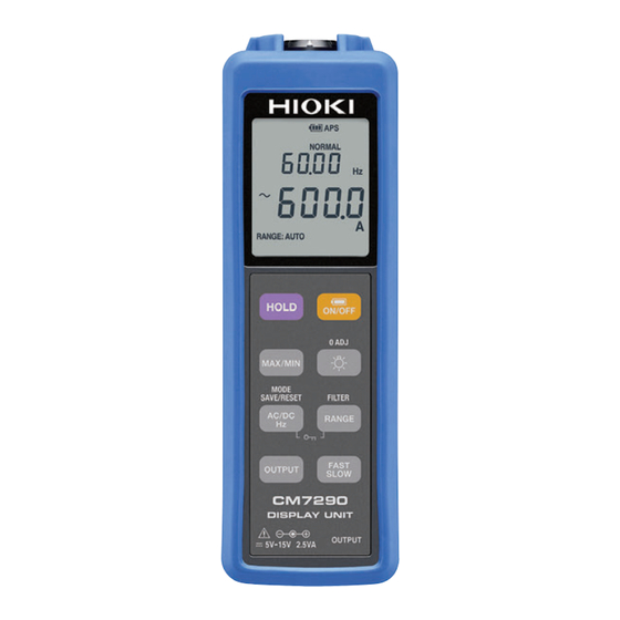
Overview 1.1 Overview and Features The CM7290 Display Unit is to be used with a current sensor equipped with a Hioki PL14 output connector. It will automatically recognize the current sensor when it is connected, and the range and output rate will be automatically set. Set the measurement mode to AC or DC so that the unit can display or output values. -
Page 16: Parts And Functions
If the protector or dust cap gets dirty or damaged, replace it as necessary. Contact your authorized Hioki distributor or reseller when ordering. The serial number consists of 9 digits. The first two (from the left) indicate the year of manufacture, and the next two indicate the month of manufacture. -
Page 17: X84; Display
Parts and Functions Display Output ×10 function enabled (p. 1 7) Save settings enabled (p. 2 0) Output mode enabled (p. 1 7) Unit Response speed (p. 1 7) Measured value (main display) Items displayed when analysis Hold function enabled (p. ... -
Page 18: X84; Warning And Battery Power Displays
Parts and Functions Warning and battery power displays Warning displays Appears when the measured value exceeds the maximum input range. Appears when the display value exceeds the output range while the output mode is PEAK or FREQ. Battery power warning display Battery full. -
Page 19: Tables Of Key Operations
Tables of Key Operations 1.3 Tables of Key Operations This section describes how to access different functions by pressing keys differently. Turn on power Short press 1-second long press while pressing key* Execute a specific Execute the operation Execute the operation command (see the written on the key written above the key... -
Page 20: X84; Measuring
Tables of Key Operations Measuring Screen display Desired operation How to set/ Enabled: Lit Description (function) cancel it Disabled: Unlit • When the unit is driven by power from an AC adapter or external DC power supply, this key is Turn the power on Display lights up disabled, and in order to... - Page 21 Tables of Key Operations Screen display Desired operation How to set/ Enabled: Lit Description (function) cancel it Disabled: Unlit "MAX": • The unit will display values Maximum value for the interval starting "MIN": when the analysis display Minimum value was activated (in the main "AVG": Analyze the display).
-
Page 22: X84; System Operation
Tables of Key Operations Screen display Desired operation How to set/ Enabled: Lit Description (function) cancel it Disabled: Unlit This function is used when the magnitude of the output is so low that it may be obscured by noise from Select output nearby equipment. -
Page 23: X84; Maintenance Operation
Tables of Key Operations Maintenance operation How to set/ Desired operation Screen display Description cancel it Used for checking the Serial No. when you are unable to Display Serial No. Turn on check the No. on the back of power while the unit because it has been pressing key installed into another device. -
Page 24: X84; Handy Functions
Tables of Key Operations Handy functions Desired operation Screen display (function) How to set/ Enabled: Lit Description cancel it : Enabled (factory Disabled: Unlit settings) • This function can be used if a no-input state will continue for approximately 1 minute when the unit is turned on. - Page 25 Tables of Key Operations Desired operation Screen display (function) How to set/ Enabled: Lit Description cancel it : Enabled (factory Disabled: Unlit settings) • Backlight will be turned off automatically after being lit Have backlight for approx. 40 seconds. turned off −...
-
Page 26: X84; Key Configurations
Tables of Key Operations Key configurations 1-second long Turn on power Short press press while pressing key Sets/cancels HOLD − Disables auto power-save Lit / Unlit − APS Unlit Cancels the Enables or switches the Enables/disables the analysis display analysis display function buzzer sound function "MAX": Maximum value... - Page 27 Tables of Key Operations 1-second long Turn on power Short press press while pressing key When using battery power: • Turn the power on When using • After APS has been battery power: − disabled, turning on • Turn the power the power again will re-enable APS •...
- Page 28 Tables of Key Operations 1-second long Turn on power Short press press while pressing key Sets/cancels ×10 output amplification function − • This operation − can only be performed during output operation. ×10 − − Lit / Unlit...
-
Page 29: Pre-Measurement Preparation
Pre-measurement Preparation 2.1 Installing the Z5004 Magnetic Strap Attach the optional Z5004 Magnetic Strap as required. The magnet can be used to attach to a wall, such as a metal surface. Strap slit Magnet... -
Page 30: Connecting The Sensor
Connecting the Sensor 2.2 Connecting the Sensor When the optional current sensor (output connector: Hioki PL14 Connector) (p. 4 3) is connected, its type will be automatically recognized, and settings that match the sensor will be configured automatically (measurement mode, current rating, output rate). -
Page 31: Supplying Power
Supplying Power 2.3 Supplying Power Installing/replacing the batteries When using the unit for the first time, be sure to install two LR6 alkaline battery (AA) batteries. Also, before measurement, check that there is adequate power in the batteries. If there is not, replace the batteries. Batteries can be replaced with the protector installed. -
Page 32: X84; Connecting The Ac Adapter (Optional)
Supplying Power Connecting the AC adapter (optional) Be sure to read “AC adapter” (p. 9 ) and “Handling of the cables” (p. 1 0) before connecting the AC adapter. Use the optional AC adapter to supply power from an outlet. When power is supplied via the AC adapter, the unit will run on AC adapter drive even if batteries are installed. -
Page 33: X84; Connecting To An External Dc Power Supply
Supplying Power Connecting to an external DC power supply Be sure to read “Handling of the cables” (p. 1 0) before connecting the power supply. When connecting to an external DC power supply, make sure that the supply has the correct rating and uses a compatible connector. -
Page 34: Turning The Power On/Off
Turning the Power On/Off 2.4 Turning the Power On/Off When using battery power Turning the power on/off Turning the power on: short press Turning the power off: long press When using the AC adapter or an external DC power supply: The unit will remain on at all times. -
Page 35: Connecting To An External Device
Connecting to an External Device 2.5 Connecting to an External Device If the unit is to be used in combination with another device, use the output cord (optional) to connect to the external device. If the sensor cable is not long enough, use an extension cable (optional). See “Options”... - Page 36 Connecting to an External Device...
-
Page 37: Measurement And Output
Inspect the unit and sensor for any damage it may have sustained during storage or shipment and verify that it is operating properly before use. If you find any faults, contact your authorized Hioki distributor or reseller. Where to check... -
Page 38: Taking Measurements
Taking Measurements 3.2 Taking Measurements 「シールド線は挟まない」 の説明を 「シールド線は挟まない」 の説明を 記載する/しないは製品ごと技術に確認する 記載する/しないは製品ごと技術に確認する ↓↓↓↓↓↓↓↓↓↓↓↓↓↓↓↓ ↓↓↓↓↓↓↓↓↓↓↓↓↓↓↓↓ Clamp the conductor Execute zero adjustment. Long press Measurement modes: AC + DC Select the measurement mode • To measure current of not more than 10 Hz, select the AC+DC [FAST/SLOW] mode, and use the key to set the response speed to... -
Page 39: X84; Types Of Output In The Different Measurement Modes
Taking Measurements Types of output in the different measurement modes AC/DC sensor sensor 3 3 3 WAVE PEAK AC/DC WAVE PEAK WAVE FREQ CAUTION • DC+AC mode and AC mode have a frequency band of about 30 kHz (−3dB) for the wave outputting (WAVE OUT) function. •... -
Page 40: X84; Setting Measurement Range
Taking Measurements Setting measurement range Measurement mode AC/DC AC/DC sensor AC/DC sensor AC sensor AC sensor AUTO AUTO AUTO ×10 ×100 99.99 Hz ×1 ×10 999.9 Hz ×1 9.999 Hz *: The ranges as a whole with a sensor connected See “Appx. -
Page 41: Changing The Display/Output Update Time (Rate) (To Faster Or Slower)
Changing the Display/output update time (rate) (to Faster or Slower) 3.3 Changing the Display/output update time (rate) (to Faster or Slower) You can change the rate at which the display/output is updated. (factory settings: NORMAL) Response speed Time FAST Fast rate NORMAL SLOW Slow rate... -
Page 42: Examples Of Measurement Waveforms
Examples of Measurement Waveforms 3.4 Examples of Measurement Waveforms Table of waveforms The table below gives examples of the typical waveforms when appropriate settings are made. See “Accuracy specifications (for display unit only)” (p. 4 5) to check the accuracy specifications for the unit. Accuracy Output specifications... -
Page 43: Bluetooth ® Communications (Only For Cm7291)
Equipment That Emits Radio Waves” or go to our website. • The CM7291 availability is limited to certain countries. For more information, contact your authorized Hioki distributor or reseller. • For more information, see the attached “Precautions Concerning Use of Equipment That Emits Radio Waves.”... -
Page 44: X84; Pairing The App With The Cm7291
Bluetooth® Communications (only for CM7291) Pairing the app with the CM7291 The instrument is automatically Home>Other Return to the home screen. Settings Instrument registered • When the app is launched for the first time (before being paired with any instrument), the instrument settings screen will be displayed. •... -
Page 45: Specifications
Specifications 4.1 General Specifications Operating Indoors, Pollution Degree 2, altitude up to 2000 m (6562 ft.) environment Operating -25°C to 65°C (-13°F to 149°F), 80% RH or less (non-condensing, temperature except for battery) and humidity Storage temperature -25°C to 65°C (-13°F to 149°F), 80% RH or less (non-condensing, and humidity except for battery) Dust-proof,... - Page 46 General Specifications In either of the following conditions: In either of the following conditions: ® ® - With Bluetooth turned OFF, - With Bluetooth turned ON, the Sensor the backlight turned off, and output mode set to OFF, and the power the output mode set to WAVE backlight turned OFF...
-
Page 47: Input And Output Specifications, And Measurement Specifications
With power ON for guaranteed accuracy Guaranteed accuracy period: 3 years Conditions of Guaranteed accuracy period from adjustment made by Hioki: 3 years guaranteed Temperature and humidity for guaranteed accuracy: 23°C±5°C (73°F accuracy ±9°F), 80% RH or less Zero-adjustment executed... - Page 48 Input and Output Specifications, and Measurement Specifications Measurement Measurement AC accuracy guaranteed Response speed response time response time frequency range and AC accuracy FAST 0.3 s 45 Hz ≤ f ≤ 1 kHz guaranteed frequency range by NORMAL 0.8 s 10 Hz ≤...
- Page 49 Input and Output Specifications, and Measurement Specifications (5) Accuracy specifications (for display unit only) 1. DC display (Measured value/MAX/MIN/AVG DC value), coupling method: DC coupling Guaranteed-accuracy Range Measurement accuracy frequency range ×1, ×10 ±0.3% rdg.±8 dgt. 2. AC display, coupling method: AC coupling •...
- Page 50 Input and Output Specifications, and Measurement Specifications 3. DC+AC display, coupling method: DC coupling • DC+AC rms value (Measured value/MAX/MIN/AVG rms) Guaranteed-accuracy Measurement accuracy Range frequency range (when the filter is set to ON, add ±0.5% rdg.) ±1.5% rdg.±15 dgt. 3 Hz ≤...
- Page 51 Input and Output Specifications, and Measurement Specifications 5. DC output Guaranteed-accuracy Range Output type Output accuracy frequency range ×1, ×10 WAVE ±0.5% rdg.±0.8 mV *1: The output accuracy is for ×1 output amplification. For ×10 amplification, add f.s. error ×10 and ±0.3% rdg. 6.
- Page 52 Input and Output Specifications, and Measurement Specifications 7. DC+AC output Guaranteed- Output accuracy Output Range accuracy (Phase specifications are only for when filter is OFF. type frequency range Add ±0.5% rdg. ±0.5 mV when filter is set to ON.) ±1.5% rdg.±1.2 mV ±1.4% rdg.±1.2 mV, phase (design value) 3 Hz ≤...
-
Page 53: Functional Specifications
Functional Specifications 4.3 Functional Specifications (1) Display and output update rate Response speed Output Display update or frequency Output update rate Notes mode rate range SLOW 1.0 s (1 time/s) Disabled NORMAL 0.2 s (5 times/s) No output − FAST 0.2 s (5 times/s) SLOW 1.0 s (1 time/s) - Page 54 Functional Specifications (2) Functions and their factory settings Factory settings Functions Description and notes Measurement DC, AC, DC + AC, or FREQ DC + AC modes Display/output • Display and output update time (rate) NORMAL update time (rate) Ranging • Auto: Optimal range is selected automatically Factory settings: RANGE: AUTO lights up RANGE: AUTO...
- Page 55 Functional Specifications Factory settings Functions Description and notes Warning displays • If input exceeds the range, the range f.s. value is didplayed with OVER segments flashing. − • When output peak exceeds the range, the lights up Auto power • Power is switched off if no operation is Enabled, but will save performed for approx.
- Page 56 Functional Specifications Factory settings Functions Description and notes Keylock Disables all key operations (except canceling Factory setting: of keylock) However, turning the power ON/OFF is possible is displayed Zero adjustment at Executes zero adjustment at power-up Factory setting: power-up is displayed Output Makes output 10 times higher than normal Factory setting:...
-
Page 57: Connection Terminal Specifications
Connection Terminal Specifications 4.4 Connection Terminal Specifications Item Symbol Notes Output jack OUTPUT Diameter 3.5 mm monaural pin-jack JEITA RC5320A Classification 3 DC external power (EIAJ RC5320A TYPE 3) 5 V to 15 V and supply (Grip portion external diameter not more than φ10 mm) 4.5 External Interface Specifications (only for CM7291) - Page 58 External Interface Specifications (only for CM7291)
-
Page 59: Maintenance And Service
How often you should calibrate the unit will depend on the usage conditions and the environment. Determine a calibration interval that is suited to your usage conditions and environment, and request to have calibration done by Hioki. Precautions when transporting the unit •... -
Page 60: Troubleshooting
Troubleshooting 5.1 Troubleshooting Troubleshooting checklist If you feel that the unit may be malfunctioning, contact your authorized Hioki distributor or reseller after carrying out the checks below. Problem Check Solution • Power will not When AC adapter is used: turn on •... - Page 61 Troubleshooting Problem Check Solution Display will not • Has DC or AC+DC • Execute zero adjustment. reset to zero measurement mode been p. 1 6 selected? • Is the possible range for • If the range is exceeded, zero adjustment exceeded? the current sensor must be repaired.
- Page 62 Troubleshooting Problem Check Solution Display value is • Is the filter function being • Disable the filter function. lower than expected used • If components of 60 Hz or p. 2 2 higher are present, the value will be low. •...
- Page 63 Troubleshooting Problem Check Solution Output value is • Carry out the same checks lower than expected as for "Display value is lower − than expected." • Is the output cord inserted all • Insert it all the way in. the way into the output jack? •...
-
Page 64: Error Displays
(rate) according frequency? to the current’s frequency. 5.2 Error Displays If any of these errors is displayed in the LCD display area, repair is required. Contact your authorized Hioki distributor or reseller for repair. Corrective action/more Error display Cause information... -
Page 65: Appendix Appx.1
Appendix Appx. 1 Range Structure, Output rate, and Power Consumption Category with a Sensor Connected Appx.1... -
Page 66: Appx. 2 Calculating Accuracy When Used With A
Calculating Accuracy When Used with a Sensor Appx. 2 Calculating Accuracy When Used with a Sensor The following examples illustrate how to calculate accuracy when measuring a 58.00 A, 60 Hz current (with the instrument set to the 10 range and AC ×... -
Page 67: Appx. 3 Combined Accuracies
Combined Accuracies (Representative values) Appx. 3 Combined Accuracies (Representative values) To see tables listing all the combined accuracies, visit Hioki’s website. Appx.3... - Page 68 Combined Accuracies (Representative values) Appx.4...
- Page 69 Combined Accuracies (Representative values) Appx.5...
- Page 70 Combined Accuracies (Representative values) Appx.6...
- Page 71 Combined Accuracies (Representative values) Appx.7...
- Page 72 Combined Accuracies (Representative values) Appx.8...
- Page 73 Combined Accuracies (Representative values) Appx.9...
- Page 74 Combined Accuracies (Representative values) Appx.10...
-
Page 75: Appx. 4 Measurement Response Waveforms
Measurement Response Waveforms Appx. 4 Measurement Response Waveforms When generating RMS or PEAK output, select an appropriate measurement response time based on the following waveform response information: RMS output (input: 3 Hz) RMS Output (3 Hz Input) RMS Output (3 Hz Input) Time (sec) Time (sec) RMS output (input: 10 Hz) - Page 76 Measurement Response Waveforms PEAK output (input: 10 Hz) PEAK Output (10 Hz Input) Time (sec) PEAK output (input: 50 Hz) PEAK Output (50 Hz Input) Time (sec) Appx.12...
Need help?
Do you have a question about the CM7290 and is the answer not in the manual?
Questions and answers