Table of Contents
Advertisement
8SMC5-USB User Manual
1.
About
1.
General information
2.
Benefits
3.
Table of specifications
4.
Specifications
2.
Safety instructions
3.
Overview and getting started
1.
One axis configuration
2.
Example of a motor connection
3.
Manual profile setting
4.
Calculation of the nominal current
5.
Possible problems and solutions
4.
Technical specification
1.
Appearance and connectors
1.
Controller board
2.
One axis system
3.
Two axis system
2.
Kinematics and rotation modes
1.
Predefined speed rotation mode
2.
Rotation for predefined point
3.
Predefined displacement mode
4.
Acceleration mode
5.
Backlash compensation
6.
Rotation reversal
7.
Recommendations for accurate rotation
8.
PID-algorithm for DC engine control
9.
Stop motion modes
10.
PID-algorithm for BLDC engine control
3.
Main features
1.
Supported motor types
2.
Motor limiters
3.
Limit switches
4.
Automatic Home position calibration
5.
Operation with encoders
6.
Revolution sensor
7.
Steps loss detection
8.
Power control
9.
Critical parameters
10.
Saving the parameters in the controller flash memory
11.
User defined position units
4.
Safe operation
5.
Additional features
1.
Operating modes indication
2.
Operations with magnetic brake
3.
Joystick control
4.
Left-Right buttons control
5.
TTL synchronization
6.
Design of multi-axis system
7.
General purpose digital input-output
8.
General purpose analog input
9.
External driver control interface
10.
Serial port
11.
Saving the position in controller's FRAM memory
12.
The Standa stages detection
6.
Secondary features
1.
Zero position adjustment
2.
User-defined position adjustment
3.
Controller status
4.
USB connection autorecovery
5.
XILab application User's guide
1.
About XILab
2.
Main windows of the XILab application
1.
XILab Start window
2.
XILab Main window in single-axis control mode
3.
XILab Main window in multi-axis control mode
4.
Application Settings
5.
Charts
6.
Scripts
Page 1 / 345
The official technical support channel @SMC5TechSupport ( https://t.me/SMC5TechSupport).
Page 1 / 345
For quick simple questions you can contact us via Telegram.
Available online Mon-Fri 8:00-16:00 UTC.
Download user manual in pdf
Advertisement
Table of Contents

Related Manuals for Standa 8SMC5-USB

Summary of Contents for Standa 8SMC5-USB
- Page 1 Page 1 / 345 Download user manual in pdf For quick simple questions you can contact us via Telegram. The official technical support channel @SMC5TechSupport ( https://t.me/SMC5TechSupport). Available online Mon-Fri 8:00-16:00 UTC. 8SMC5-USB User Manual About General information Benefits Table of specifications...
- Page 2 Page 2 / 345 XiLab Log Controller Settings Settings of kinematics (Stepper motor) Motion range and limit switches Critical board ratings Power consumption settings Home position settings Synchronization settings Brake settings Position control Settings of external control devices UART settings General purpose input-output settings Motor type settings Settings of kinematics (DC motor)
- Page 3 Page 3 / 345 8MR174 - Motorized Rotation Stage 8MR190 - Motorized Rotation Stage 8MR191 - Motorized Rotation Stage 8MRB250 - Large Motorized Rotation Stage 8MRU - Universal Motorized Rotation Stages 8MPR16-1 - Motorized Polarizer Rotator 8MRH240 - Large High Capacity Rotary Stage Vertical Translation Stages 8MVT100 - Vertical Translation Stage 8MVT120 - Vertical Translation Stage...
- Page 4 Page 4 / 345 1. About General information Benefits Table of specifications Specifications Page 4 / 345...
- Page 5 The motor connector on the controller board is the same as one used by Standa company and it fits to all the Standa stages. USB connector provides easy communication and work with computer.
- Page 6 Motion is smoother and faster than ever with innovation encoder based close-loop on all 8SMC5-USB motor controllers. It combines advantages of BLDC motor control with cheapness of conventional stepper motors. No hidden catch, no stall or hitch, just free move!
- Page 7 Page 7 / 345 1.3. Table of specifications Power supply external 12V - 48V DC Current up to 5A (depending on the voltage) from external power supply consumption Current up to 3A motor winding Protection types current overload protection, voltage overload protection, short circuit protection, motor hotplug/unplug protection move left/right, move to point, shift on delta, continuous speed, acceleration and deceleration ramps, backlash Motion modes compensation mode, automatic home position calibration mode...
-
Page 8: Specifications
Additional features available via motor connector Processing the signals from one or two limit switches; software configurable. The Standa stages recognition and automatic downloading of the configuration file right from the stage if the last one supports this feature. The "step loss" detection and position recovery using either a revolution sensor or a quadrature encoder (if the stage supports this feature). -
Page 9: Programming The Controller
Page 9 / 345 Limit switches indication pins designed for LED direct connection. Specifications: TTL 3.3V, 2mA. Digital "Power" and "Status" pins duplicate the status LED and designed for direct connection of LEDs. Specifications: TTL 3.3V, 2mA. External driver control interface allowing to control any type of external driver using three signals: enable, direction, clock. Multiaxis systems development. -
Page 10: Safety Instructions
Top view of the controller board. A grounding terminal marked with the red square Typical connection diagram for a controller (board, systems in box): Motor Power Controller 220 V supply 8SMC5-USB Controller grounded via minus electrode of power cable connection diagram Motor Power Controller 220 V supply... -
Page 11: Controller Board
Page 11 / 345 Warning. Power supply unit should be able to supply sufficient current to rotate the motor. As an absolute minimum it should be able to supply where is the minimum working current of power supply unit, is the operating current in the winding, is power supply unit stabilized voltage, and is rated operating voltage of the motor. - Page 12 XILab software for Windows 7. One axis configuration - a brief description of the beginning of work with the controller + 8SMC5-USB for one axis +. It is also considered quick XiLab setup and lists all necessary equipment. Example of a motor connection - connection of stepper motor Nanotec ST5918L3008-B with encoder CUI INC AMT112S-V to 8SMC5-USB controller.
-
Page 13: System Requirements
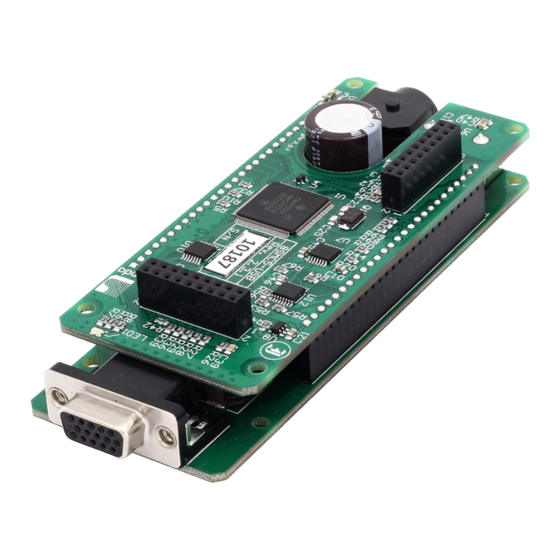
All necessary software to work with the controller can be downloaded from software page. USB A - mini-B cable USB-A to mini-USB-B cable. For detailed information about the USB cable please read the data connector chapter. 8SMC5-USB controller Page 13 / 345... - Page 14 Page 14 / 345 The motor controller board. The controller appearance may differ from the one shown on the above figure depending on its configuration and version. For detailed information about versions please read the Appearance and connectors 8SMC5 chapter. Positioner or motor The stepper motor-based positioner.
- Page 15 Page 15 / 345 XILab main installation window. Press “Next>” button and follow the instructions on screen. All the necessary software including all drivers, packages and programs will be installed automatically. After installation is finished, the XiLab software starts by default and the following window will open: XILab "No devices found"...
- Page 16 Page 16 / 345 XILab main window. Open “Settings...”, then press “Restore from file...” and select the configuration file for your positioner from the opened C:\Program Files\XILab\profiles\ folder. The values applicable for your positioner will automatically fill all the fields of “Settings...” menu. If the necessary file isn't found, please refer to the Configuration files chapter.
-
Page 17: Functional Test
Page 17 / 345 XILab, the Settings menu window. Warning. For the controller to work with stepper motors it is required to properly set up: working current, displacement limits and limit switches critical parameters, limiters, power supply mode. If you decide to configure your controller by yourself, please check these parameters carefully! Congratulations, your controller is ready for operation! Functional test Check if the controller is configured properly by pressing left or right button in the central row of XILab main window control buttons. - Page 18 Page 18 / 345 Control from user applications Xilab software is a convenient way to control stages connected to 8SMC5-USB controller. However, if you need to control the 8SMC5- USB from your own application, you may do so by using libximc library.
- Page 19 Preparation To get started, we need: Motor; Encoder; Pinout of D-SUB connector for 8SMC5-USB; Motor datasheet Encoder datasheet Soldering equipment: soldering-iron, wires, flux, solder, nippers, heat shrink tubes of different sizes; Screws M2.5x6 for fixing the encoder; D-SUB cover + connector (male) and wires for cable manufacturing;...
- Page 20 Page 20 / 345 Connecting the motor and encoder to the controller Before you begin, assemble the encoder in accordance with the appropriate instructions. The motor without encoder. Note 2 holes M2.5 to which is usually attached an encoder Motor with attached encoder Let us look in the specification of the engine and find the wiring diagram (for Nanotec ST5918L3008-B it is at the bottom right in the specification): Motor contacts...
- Page 21 Page 21 / 345 To connect encoder, open its datasheet and find 5 contacts on encoder connector: A+ (channel A), B+ (channel B, shifted relative to A by 90 degrees), Z+ (rev counter), 5V, GND. They should be taken from the encoder as 5 separate wires and put together with the wires from the motor as they then go to a connector.
- Page 22 Page 22 / 345 Now you can connect it to 8SMC5-USB. Description and profile settings are given in the next chapter Manual profile setting Page 22 / 345...
- Page 23 Page 23 / 345 3.3. Manual profile setting Introduction 3.3. Manual profile setting All necessary parameters are set after motor connection (see Example of a Introduction motor connection where the Nanotec ST5918L3008-B motor connection is Getting started described). There we will consider the setting of the profile for Nanotec Nominal current setting ST5918L3008-B stepper motor.
- Page 24 Page 24 / 345 calculate the number of steps per revolution, knowing that one revolution consists of 360 degrees. Make sure that movement to the right from the main window of XiLab corresponds to the movement to the right of the stage. If not, then check the box Reverse field Stepper motor ->...
- Page 25 Page 25 / 345 If it is possible to get limit switches activate them and note the correspondence between indicators in XiLab and each particular switch. Then start the system at the low speed (<100 ш/с) when it is far away from limit switches and make sure that the system moves to the right switch.
- Page 26 Page 26 / 345 It is possible to activate the position control by encoder. To do this, in the tab Position control mark Position control and specify allowable error in terms of encoder counts in the Threshold field. Then, when a mismatch between position and encoder counts occurs, indicator SLIP will light in the bottom of XiLab main window.
- Page 27 Page 27 / 345 3.4. Calculation of the nominal current In order to stepper engine gave maximum torque, but it does not overheat, it is important to specify such technical characteristic as the rated current. The greater a current in the motor winding, the greater the torque at the axis. It is important to remember that with an increase a current flowing through the winding, thermal power released by the motor increases.
- Page 28 Motor controllers in this case will provide the maximum torque without overheating the engine. For all Standa motorized positioners prepared configuration files that contain the specified nominal current as rms. The corresponding flag is set. Thus the engines operate at optimum settings.
-
Page 29: Possible Problems And Solutions
Ask a question Send an e-mail: 8smc4@standa.lt Controller is not found in XiLab Solution: Comment to the diagram: 8SMC5-USB-B9-1 - one axis system 8SMC5-USB-B9-2 - two axes system The following decision maps show the actions for different operating systems. Windows:... - Page 30 Page 30 / 345 Linux: Page 30 / 345...
- Page 31 Page 31 / 345 Comment to "Can't open device" problem solution: When working with USB-... converter in Linux it appears as /dev/ttyUSB device. XiLab shows it in a list, but when you try to open it, an error "can't open device" occurs due to the lack of permissions to the device. To solve this problem, create a file: /etc/udev/rules.d/31-ximc.rules and add the next line into it: SUBSYSTEM=="usb", ATTR{idVendor}=="067b", MODE="0666"...
- Page 32 Page 32 / 345 Unable to rotate the motor by the controller Controller has Alarm state Click Stop in the main window of XiLab. Controller must return to its normal state. If this approach was not helpful and Alarm state emerged again, do the following: Being in XiLab go to the Maximum ratings tab.
- Page 33 Page 33 / 345 proper motor current in the winding varies according to a sine or cosine. In the broken motor much stronger differences of the current from harmonic form can be noticed. Working case In the charts below you can see the problems. For example, winding B is open circuit. Probably it is broken. Also, voltage and current forms are distorted.
- Page 34 Design of multi-axis system General purpose digital input-output General purpose analog input External driver control interface Serial port Saving the position in controller's FRAM memory The Standa stages detection Secondary features Zero position adjustment User-defined position adjustment Controller status USB connection autorecovery...
-
Page 35: Appearance And Connectors
Page 35 / 345 4.1. Appearance and connectors 8SMC5-USB controllers are available in 3 different versions: Controller board One axis system Two axes system Page 35 / 345... - Page 36 Page 36 / 345 4.1.1. Controller board 8SMC5 Dimensions and arrangement Structurally the controlled is designed as two boards, 46x126,75mm each, rigidly connected to each other. A logic controller and control systems are mounted at the bottom board, a power part is at the top board. A radiator at the power part is available. Top view on the controller.
- Page 37 4 - Phase A of SM or + DC of the motor or phase A on BLDC motor 5 - 500mA - for 8SMC5, stabilized output for encoder power supply 6 - One-wire interface for positioner identification (for Standa hardware only) 7 - Logic ground for limit switches, encoder, etc.
-
Page 38: Backplane Connector
Page 38 / 345 IMPORTANT. Never supply the power to the controller and do not plug it to power connector if you are not confident that your power supply parameters conform to the requirements. Never attempt to plug the power supply to the controller if you are not sure power supply unit and controller connectors are compatible! The acceptable connection parameters are described in Safety... - Page 39 Page 39 / 345 Pin function of CN1: 1 - Power GND 12-48В. 2 - Joy, an analog 0-3 V input used for external joystick connection. 3 - Power GND 12-48В. 4 - Pot, an analog 0-3 V input used for general purpose.
- Page 40 4 - Phase A of SM or + DC of the motor or phase A on BLDC motor 5 - 500mA - for 8SMC5, stabilized output for encoder power supply 6 - One-wire interface for positioner identification (for Standa hardware only) 7 - Logic ground for limit switches, encoder, etc.
- Page 41 Page 41 / 345 One- and two-axis controller models in metal cases use Kycon 4-pin DC power connector (part number KPPX-4P, anacapa.kycon.com). Pinout: 1 - Power, "-". 2 - Power, "+". 12-48V. 3 - Power, "-". 4 - Power, "+". 12-48V. IMPORTANT.
- Page 42 Page 42 / 345 One-axis controller model contains a HDB-26 female DSub connector. Pinout of the supplementary HDB-26 connector, front view. Pinout: 1 - NC, not used. 2 - NC, not used. 3 - NC, not used. 4 - GND, ground. 5 - NC, not used.
- Page 43 4 - Phase A of SM or + DC of the motor or phase A on BLDC motor 5 - 500mA - for 8SMC5, stabilized output for encoder power supply 6 - One-wire interface for positioner identification (for Standa hardware only) 7 - Logic ground for limit switches, encoder, etc.
- Page 44 Page 44 / 345 One- and two-axis controller models in metal cases use Kycon 4-pin DC power connector (part number KPPX-4P, anacapa.kycon.com). Pinout: 1 - Power, "-". 2 - Power, "+". 12-48V. 3 - Power, "-". 4 - Power, "+". 12-48V. IMPORTANT.
- Page 45 Page 45 / 345 A single-axis or two-axis controller model may contain a 9pin DSub male joystick connector. Pinout of the joystick connector, front view. Pinout: 1 - BUT_R_1, right button input, axis 1. 2 - Joy_2, analog 0-3V joystick input, axis 2.
- Page 46 Page 46 / 345 Pinout: 1 - RX_2, serial port input, axis 2. 2 - Synchronization input, axis 2. 3 - TX_2, serial port output, axis 2. 4 - GND, ground. 5 - Synchronization output, axis 2. 6 - Synchronization input, axis 1. 7 - Synchronization output, axis 1.
- Page 47 Page 47 / 345 4.2. Kinematics and rotation modes Predefined speed rotation mode Rotation for predefined point Predefined displacement mode Acceleration mode Backlash compensation Rotation reversal Recommendations for accurate rotation PID-algorithm for DC engine control Stop motion modes PID-algorithm for BLDC engine control Page 47 / 345...
- Page 48 Page 48 / 345 4.2.1. Predefined speed rotation mode Predefined speed rotation mode is the main operating mode of the controller for all the motor types. It allows to maintain the predefined rotation speed at a distance from the destination point and is usually used simultaneously with Rotation for predefined point Predefined displacement modes.
- Page 49 Page 49 / 345 4.2.2. Rotation for predefined point The rotation to predefined point mode is the main operating mode for all the types of motors and is usually used simultaneously with predefined speed rotation mode. It provides moving the stage to the defined position with absolute value for destination point coordinates which is different from predefined displacement mode.
- Page 50 Page 50 / 345 4.2.3. Predefined displacement mode The predefined displacement mode provides displacement of the stage for predefined value relative to zero position (if this is a first command since the controller started) or relative to position reached by the motor after the previous commands are completed, i.e., the destination point coordinate is a relative value.
-
Page 51: Acceleration Mode
Page 51 / 345 4.2.4. Acceleration mode The acceleration function is active by default. The acceleration is used for smooth start or finish of the rotation without shocks that are inevitable when the predefined speed is reached instantly. Moreover, inertia of rotor and the other components of stage usually doesn't allow instant gathering of high speed which results in the loss of steps as well as failure in rotation during the operation without feedback. -
Page 52: Backlash Compensation
Page 52 / 345 4.2.5. Backlash compensation Backlash occurs in any mechanical device, e.g., in reduction gear or in worm-gear. Backlash results in differences in physical stage position when approaching the same point from different directions, whereas the motor shaft is exactly in the required position. Backlash compensation mode is used in order to eliminate such ambiquity. - Page 53 Page 53 / 345 4.2.6. Rotation reversal It is a common agreement that the coordinate increase corresponds to movement to the right, whereas its decrease corresponds to movement to the left. The rotation is to be reversed either if this rule is not satisfied due to physical stage location, or if the stage is supplied with an anchor which is pointed so that it doesn't match coordinate increase.
- Page 54 Page 54 / 345 4.2.7. Recommendations for accurate rotation The controller can automatically adjust itself for the required mode, in order to maintain either the speed or the coordinate. However, both the speed and the adjustment property depend on the controller settings. The stepper motor working in steps and microsteps positioning mode can instantly reach the required operating conditions.
- Page 55 Page 55 / 345 4.2.8. PID-algorithm for DC engine control Algorithm description DC engine is controlled by the PID regulator, with the coordinate as the controlled parameter. The controlled coordinate changes according to motion settings and incoming commands to provide motion capability. We will call controller coordinate the running position.
- Page 56 Page 56 / 345 Time until final stop in target position (lower is better). No slip on approach to the target position. No oscillations around target position before stopping. No spontaneous shifts from the target position after stopping. Low noise when moving. Noise level is increased when only one of the PID coefficients is increased. One can choose individual criterion priority depending on the task at hand when tuning PID regulator.
-
Page 57: Emergency Stop
Page 57 / 345 4.2.9. Stop motion modes There are two stop motion modes in the controller: emergency stop; stop with deceleration. Emergency stop Emergency stop is initiated by the command STOP. The controller tries to instantly stop the rotation of the motor shaft. This can lead to missed steps in a stepper motor, if no feedback is used. - Page 58 Page 58 / 345 4.2.10. PID-algorithm for BLDC engine control Algorithm description BLDC engine is controlled by the PID regulator, with the coordinate as the controlled parameter. The controlled coordinate changes according to motion settings and incoming commands to provide motion capability. We will call controller coordinate the running position.
- Page 59 Page 59 / 345 2. Set the coefficients calculated by formulas, click Apply. Click the Zero button on the main XiLab window. Set 0 to the Move to field, send the command. The engine should stop. Try to move the position manually, make sure that the response is correct - the engine tries to return to zero position (the encoder reverse is set correctly).
-
Page 60: Main Features
Page 60 / 345 4.3. Main features Supported motor types Motor limiters Limit switches Automatic Home position calibration Operation with encoders Revolution sensor Steps loss detection Power control Critical parameters Saving the parameters in the controller flash memory User defined position units 8SMC5 Page 60 / 345... -
Page 61: Supported Motor Types
Page 61 / 345 4.3.1. Supported motor types Currently the controller supports stepper and DC motor types. The parameters of supported motors are described in Specifications chapter. Stepper motors Rated current is the main parameter of the stepper motor. The rated current is adjustable at the Settings of kinematics (Stepper motor) section. - Page 62 Page 62 / 345 IMPORTANT. Wrong PID regulator settings might lead to stage failure. All supplied profiles are preset with correct PID settings. It is not recommended to alter these settings unless absolutely necessary. BLDC motors Firmwares 4.1.x and older support BLDC motors controlling. Like DC motors, controlling BLDC motors reqiures feedback. Main BLDC motor parameters are maximum current and number of poles, which can be set on Settings of kinematics (BLDC motor).
- Page 63 Page 63 / 345 Motor RT/L 0.19576 0.07253 0.07168 4118L1804R 0.02715 4118S1404R 0.02844 4247 0.0273 D42.3 0.0223 5618 0.0146 5618R 0.0146 5918 0.0116 5918B 0.012 VSS42 0.029 VSS43 0.0256 0.04248 DCERE25 0.2106 The motor's overheat is determined by this sequence: calculation.
- Page 64 Page 64 / 345 4.3.2. Motor limiters Motor winding current and voltage limiters and motor shaft revolution speed limiters are provided to ensure safe operation. These limiters, if activated, will lead to gradual power and rotation speed decrease until the parameters being limited are within acceptable range.
-
Page 65: Limit Switches
Page 65 / 345 4.3.3. Limit switches Limit switches designation Limit switches are designed in order either to prevent the stage movement out of permissible physical movement range or to limit its movement range according to user-defined requirements. Incorrect setting of the limit switches may result to stage jam if the controller goes beyond the permissible range. - Page 66 Page 66 / 345 The settings of which limit is left or right is required by the controller. Sometimes it is unknown a priori, just it is clear that both limit switches are connected and fire if the corresponding limit of the motion range is reached. The stage jam is possible if the limit switches are configured improperly.
- Page 67 Page 67 / 345 4.3.4. Automatic Home position calibration This feature is used for detection and placing the movement to the starting position. This option of the controller is designed for simple search of "Home", or "Zero" position by user himself, with no need of any programming skills. The Home position is set relative to one or two external sensors and/or to an external signal.
- Page 68 Page 68 / 345 How to use the script: place the movement to the desired position launch the script and wait until it's finished. As a result, the movement will be in the same position and all the following calls of homing function will move it there. Make sure to save the settings to controller's nonvolatile memory.
- Page 69 Page 69 / 345 4.3.5. Operation with encoders Application of encoders Encoders are designed for creation of accurate and fast feedback according to the coordinate for all the electric motor types.The feedback is performed by the motor shaft position, by stage's linear position, by the motorized table rotation angle or by any other parameter related to the shaft position and measured by using the two-channel quadrature encoder complying the requirements described in Specifications SMC5...
-
Page 70: Encoder Connection
Page 70 / 345 Encoder connection The encoder is connected to the controller via D-SUB 15 pin connector, which is in all systems ( controller board, one-axis two-axis in box The diagram of single-ended encoder connection using D-SUB 15 pin connector. The diagram of differential encoder connection using D-SUB 15 pin connector. -
Page 71: Revolution Sensor
The revolution sensor should be connected to the controller via 15pin D-SUB connector, which is in all systems ( controller board, one- axis two-axis in box). Scheme of revolution sensor connection to the 8SMC5-USB based system Page 71 / 345... - Page 72 Page 72 / 345 4.3.7. Steps loss detection This mode is generally used while operating the stepper motor at full speed or limit loads when the shaft jam resulting to the steps loss is possible. In this case an additional position sensor (revolution sensor) or encoder...
- Page 73 Page 73 / 345 Note. The position control of the revolution sensor can't detect the shaft rotation at the zero speed, i.e., if the motor is shut down and the shaft is rotated manually, it won't be detected. Page 73 / 345...
-
Page 74: Power Control
Page 74 / 345 4.3.8. Power control Current consumption reduction Controller has an option to set current when idle to reduce power consumption. This mode is active by default. It is widely used to lower stepper motor heating in hold mode while keeping position maintenance accuracy. Hold current is set as a percentage of nominal winding current. - Page 75 Page 75 / 345 4.3.9. Critical parameters Minimum and maximum values of currents, voltages and temperatures are used for safe controller operation. Any value out of acceptable range leads to the motion stop, windings power-down and Alarm state for the controller. Exiting the Alarm state is possble only after the critical parameter returns to normal and the STOP command is sent to the controller.
- Page 76 Page 76 / 345 4.3.10. Saving the parameters in the controller flash memory The controller provides an option to save all its parameters into the non-volatile memory. The configuration is restored when the controller is powered on, after that the controller itself is instantly ready for operation. The stage requires no new adjustment every time the power is on.
- Page 77 Page 77 / 345 4.3.11. User defined position units Controller position is set and read in stepper motor steps or encoder counts, if encoder is available and enabled. Is it convenient to set position in mm (in case of translation stages), in degrees (in case of rotator stages) or in any other natural units. Controller software can translate coordinates to user-defined units: user can set a ratio, where a certain amount of controller steps is equal to the certain amount of user-defined units.
-
Page 78: Safe Operation
Page 78 / 345 4.4. Safe operation Several controller settings are directly connected with safe operation. If these settings are set wrong it may lead to controller or stage damage. Positioning element can be damaged by exceeded power, rotation speed, or by moving outside the allowed movement range. Usually it is enough to load a preset profile for your stage for safe operation, where all necessary settings are already made. -
Page 79: Additional Features
Joystick control Left-Right buttons control TTL synchronization Design of multi-axis system General purpose digital input-output General purpose analog input External driver control interface Serial port Saving the position in controller's FRAM memory The Standa stages detection Page 79 / 345... - Page 80 Page 80 / 345 4.5.1. Operating modes indication Controller status Mode indication is provided in controller. For this purpose one dual-color LED is located on the board. Green Power indicator shows presence of 3.3 V power supply of controller. Red Status indicator represents controller operating mode. Simultaneous glowing of both lights looks like yellow glow.
- Page 81 Page 81 / 345 Connection of the limit indicators to the controller board One-axis and two-axis systems LEDs on the front panel of controllers in the box ( one-axis two-axis systems) are indicators for power, status and limit switches, therefore a connection diagram is not required. Page 81 / 345...
-
Page 82: Description Of Operation
In order to use magnetic brake check if your controller system is equipped with a special converter board. Models which meets this demands can be identified by letters BR in its title, for example 8SMC5-USB-B8-1BR Contact pin responsible for magnetic brake control in boxed versions of controller is located on the HDM26 26 pin connector connection diagram is shown below. - Page 83 Page 83 / 345 Connection of magnetic brake to one-axis or two-axis systems Page 83 / 345...
-
Page 84: Joystick Control
Page 84 / 345 4.5.3. Joystick control General information Controller accepts an input from an analog joystick with voltage in 0-3 V range. Voltage in the equilibrium (central) position and voltage in minimum and maximum position can be set to any value from the working range, if the following condition holds: minimum position <... - Page 85 Page 85 / 345 Connection of joystick to the controller board via BPC connector One-axis and two-axis systems Joystick connector is available only in two-axis system. A connection diagram is shown below. Connection of joystick to the two-axis system via D-SUB 9 pin connector Page 85 / 345...
- Page 86 Page 86 / 345 4.5.4. Left-Right buttons control For each system it is possible to control the movement of a motor with the buttons. Active button state is programmable and can be logical zero or one. Controller supports a 10-item speed array MaxSpeed[0-9], which is used both for joystick and button control.
- Page 87 Page 87 / 345 Scheme of buttons connection to the HDB-26 connector Page 87 / 345...
-
Page 88: Principle Of Operation
Page 88 / 345 4.5.5. TTL synchronization Principle of operation TTL-synchronization is used to synchronize controller motion with external devices and/or events. For example, the controller can output synchronization pulse each time it moves a certain distance. Vice versa, controller can shift a certain distance on incoming synchronization pulse, for example from an experimental setup which is ready to move to the next measurement position. -
Page 89: Pulse Time
Page 89 / 345 Note. Sync in settings may be saved in controller flash (non-volatile) memory. In this case everything related to synchronization may also be said about autonomous controller operation. For example, you may set up shift on offset on syncin pulse with syncout pulse on movement stop and connect the controller to a standalone measurement device, which starts measurements on its own input sync pulse and outputs a sync pulse on measurement end. - Page 90 Page 90 / 345 Clutter time Movement does not start because input pulses are shorter than debounce time Warning. If a second syncin pulse is received while controller is still moving then the end position will be offset by two times the shift distance from the start, if a third pulse is received, then by three times, etc. Clutter time Clutter time Motion stops Moving time...
- Page 91 Page 91 / 345 Motion stops Clutter time Clutter time Moving time Moving time Motion starts Two separate shifts with two start and two stop phases Default setting is active state is one, movement on raising edge. Synchronization input may be inverted to the active state is zero, movement on trailing edge.
- Page 92 Page 92 / 345 Note. If syncout pulse length is measured in distance units and, for example, is equal to 10 stepper motor steps and "syncout pulse on stop" mode is active, then the active state on synchronization output will be set on the movement end, but will be cleared only when the motor will move 10 more steps during the next movement.
- Page 93 Page 93 / 345 Note. Whenever syncout pulses overlap they are merged into one pulse. _Syncout pulse merge illustrated, pulse generation on start, stop and shift on offset (pulse length measured in microseconds) Synchronization settings setup in XiLab is described in Synchronization settings section.
-
Page 94: Multiaxis System Design
Page 94 / 345 4.5.6. Multiaxis system design Controller axes in multiaxis systems are identified by the controller serial number. Each controller has its own unique serial number, which may be seen in XiLab software on About controller page. One can read controller serial number using get_serial_number function (see Programming guide). - Page 95 Page 95 / 345 4.5.7. General purpose digital input-output Output is located on connector. It allows user to configure it as input or output. Logical level one is considered to be active. However it can be inverted so that logical level zero is considered active. Type Logic zero level 0 V Logic one level...
- Page 96 Page 96 / 345 Among two box versions, only two axis system has the digital input/output. Corresponding contacts output on the HDB-26 connector. Scheme of connection to digital input/output for two-axis system Page 96 / 345...
- Page 97 Page 97 / 345 4.5.8. General purpose analog input Analog input may be used for other purpose. For example, it can be used to measure any external signal. Value at the analog input may be read by the GETC command and is visible in the XiLab charts.
- Page 98 Page 98 / 345 4.5.9. External driver control interface Interface allows to control any external driver with a help of 3 standard signals: enable, direction, clock. This mode is convenient when controller power capability is not enough but it is desirable to use its capabilities such as limit switches, revolution sensor, position control, scripting language, multiaxis systems, joystick/button control, magnetic brake, etc.
- Page 99 Page 99 / 345 Page 99 / 345...
-
Page 100: Serial Port
Page 100 / 345 4.5.10. Serial port Controller allows control through UART serial port with TTL 3.3 V logic. UART outputs are located on connector. Because of widespread availability of UART and adapters to USB, Bluetooth, Ethernet and other standard interfaces there is an option for wireless control (Bluetooth) or control over the internet (Ethernet). - Page 101 Page 101 / 345 Recommended scheme of connection to serial port pins for two-axis system Page 101 / 345...
- Page 102 Page 102 / 345 4.5.11. Saving the position in controller's FRAM memory Controller has a function which automatically remembers its last position. This allows one to power-off the controller after it has stopped. On the next power-on the controller will appear in the same motor position, logical position and encoder value. This will work if during the time controller was off the motor shaft was not rotated by external means.
- Page 103 4.5.12. The Standa stages detection Newest Standa positioners (please check with the manufacturer for the list of exact models) have an option to store settings and informational parameters in the internal positioner memory. This chip is flashed with correct settings, which allows one to skip optimal positioner configuration and to start working with the positioner right out of the box.
-
Page 104: Secondary Features
Page 104 / 345 4.6. Secondary features Zero position adjustment User-defined position adjustment Controller status USB connection autorecovery Page 104 / 345... - Page 105 Page 105 / 345 4.6.1. Zero position adjustment Controller supports setting of zero position. This function should be used for anchor marked stages, so that anchor position matches logical zero. Also, this function is convenient to use in case there is a single chosen physical position. To set zero position a special command is used.
- Page 106 Page 106 / 345 4.6.2. User-defined position adjustment A SPOS command can be used if it is necessary to set position and/or encoder value to some user-defined position instead of zero. New step/microstep position and encoder count values are passed as parameters to this command. If only one of these counters is needed one should use ignore flags to filter required fields.
-
Page 107: Controller Status
Page 107 / 345 4.6.3. Controller status Controller tracks its own status and can transfer it in the status structure of the GETS command. Controller status contains information about performed movement, its result, state of power supply, state of encoder, state of motor windings, digital input-output states, numeric information about position and powering voltage and currents and also error flags. - Page 108 Page 108 / 345 Power voltage (in tens of mV) USB current (in mA) USB voltage (in tens of mV) Microprocessor temperature (tenths of degrees Celsius) Status flags There are several types of flags: control command error flags, critical parameter flags, general error flags and state flags. Many flags do not remove themselves and should be reset by the STOP command.
- Page 109 Page 109 / 345 4.6.4. USB connection autorecovery This unit is designed to reboot the USB in the event of loss of communication (for example, this may occur in the event of electrostatic discharge or when the USB is disconnected without powering down the controller). The on/off state of this unit is determined by the USB_BREAK_RECONNECT flag (see Critical parameters).
- Page 110 Page 110 / 345 5. XILab application User's guide About XILab Main windows of the XILab application XILab Start window XILab Main window in single-axis control mode XILab Main window in multi-axis control mode Application Settings Charts Scripts XiLab Log Controller Settings Settings of kinematics (Stepper motor) Motion range and limit switches...
- Page 111 Page 111 / 345 5.1. About XILab XILab features a user-friendly graphical interface, which is designed for stages control, diagnostic and fine tuning of the motors driven by the controllers. XILab allows quick adjustment of connected stage by loading of previously prepared configuration files. The control process can be automated with script language that can be used either directly or to speed up the process of customized control program development.
- Page 112 Page 112 / 345 5.2. Main windows of the XILab application XILab Start window XILab Main window in single-axis control mode XILab Main window in multi-axis control mode Application Settings Charts Scripts XiLab Log Page 112 / 345...
- Page 113 Page 113 / 345 5.2.1. XILab Start window When started, XILab opens a controllers detection window. By means of libximc library, XILab queries controllers connected to the system and displays a list of found and successfully identified controllers. XILab Start Window, 0 controllers found XILab Start Window, 1 controller found XILab Start Window, 2 controllers found The list of found controllers is displayed on the start screen.
- Page 114 Page 114 / 345 Note: Since the libximc library opens XIMC devices in the exclusive access mode, when you start subsequent copies of XILab application, only free controllers will be found and available for selection. Page 114 / 345...
- Page 115 Page 115 / 345 5.2.2. XILab Main window in single-axis control mode 5.2.2. XILab Main window in single-axis control mode Motion Control Unit Movement without specifying the final position Movement to the target point Target position for motion commands Attenuator Control Unit Controller and motor status Controller Power Supply Motor status...
- Page 116 Page 116 / 345 XILab Main Window in Attenuator mode In the left part of the window in Power and Motor groups of parameters status of the controller and the motor is available. In the central part of the window there is the Control group, containing the elements of motor motion control. On the right there is a group of buttons to control the application as a whole.
- Page 117 Page 117 / 345 Button Left to the border will make the motor rotate to the left border of the slider. Right to the border , respectively, will do it to the right edge of the slider. When you press and hold the keyboard buttons Right or Left and the slider block has input focus, the movement starts in the direction of increasing or decreasing coordinate.
- Page 118 Page 118 / 345 Controller Power Supply Power group of parameters contains the following indicators: Source - source of power supply for controller. The controller may be powered by USB or by External power source. Power voltage - voltage supplied to the power module. Power current - current consumption of the power module.
- Page 119 Page 119 / 345 Program status Program group of parameters contains the following indicators: Sync buf free - free slots in the syncin command buffer (see description of ASIA command). Group of application control buttons Settings... button opens controller settings, see Application Settings.
- Page 120 Page 120 / 345 5.2.3. XILab Main window in multi-axis control mode XILab Main window In the top left part of the screen in the Position parameter group there are indicators of the current position. In the bottom left part of the window there is the Joystick and Control blocks, which are a graphical control element for several axes and a button block respectively.
-
Page 121: Control Block
Page 121 / 345 Virtual joystick block In this block, the current coordinate of the controllers is visualized as a dot with two lines on the plane for X-Y axes and the line for the Z axis. There are several possible ways to control movement of the controllers: When you click anywhere on the X-Y plane or in the Z column, the corresponding controller or controllers start to move to the selected coordinate in accordance to its own movement settings. - Page 122 Page 122 / 345 Control block The Go home button searches for the home position independently for each of the controllers; see Home position settings. The Zero button resets the current position of the motor and value of the encoder for each controller. The Soft stop button executes a soft stop for each of the controllers.
- Page 123 Page 123 / 345 Block of status indicators for controllers and motors Here are the three blocks of indicators of controllers and motors for axes X, Y and Z. In the title of the block the serial number of corresponding controller is displayed. Each block contains the following indicators: Voltage - the voltage at the power section of the motor.
- Page 124 Page 124 / 345 Common settings dialog window Common settings window contains axis order settings, curve drawing options and logging settings. You can reorder axes by choosing the axis serial, then pressing "up" or "down" buttons on the right. First axis in the list, that is, an axis with serial number listed to the right of "X axis SN = " label will be referred to as "X axis", the second one as "Y axis", the third one, if it is available, as "Z axis".
-
Page 125: Application Settings
Page 125 / 345 5.2.4. Application settings Settings button from the main window opens the Settings window. XILab Settings Main Window Application settings are presented as a hierarchical tree and are divided into three groups: controller settings - "Device configuration", XILab application settings - "Program configuration", characteristics of a stage - "Stage confuguration". - Page 126 Page 126 / 345 The OK Button closes the Settings window and saves all changes to the settings to the controller. The Cancel button closes the window without saving. The Apply button saves the settings without closing the window. The Reset button resets all setting changes that were made since the Apply button was pressed, or after opening the Settings, if the Apply button was not pressed.
- Page 127 Page 127 / 345 5.2.5. Charts Button Chart of the main window opens a window for working with charts. 5.2.5. Charts Values displayed charts Button functions XILab Charts window In the left part of the window there are Charts of variables, in the right side of the window there is the Control block, which contains the charts control elements.
-
Page 128: Button Functions
Page 128 / 345 motor; PWM level the PWM duty factor (only for DC motors); Temperature is temperature of controller processor; Joystick is value of input signal from the joystick; Analog input is value of analog input; Flags shows the state of the controller flags. Button functions Clear - clears the stored data and the Charts window;... - Page 129 Page 129 / 345 5.2.6. Scripts The "Scripts" button on the main window opens a window for working with scripts. XILab scripting window On the left side of the window a text edit field is located, on the right side of the window a Control block is located, which contains control buttons.
- Page 130 Page 130 / 345 5.2.7. XILab log XILab log window XILab log at the bottom part of the main window shows libximc library messages. It also shows messages from XILab application and Scripts interpreter. Log has 4 columns: date and time of record, the source and the message text. Messages have a logging level indicating message importance: error, warning and informational message.
-
Page 131: Controller Settings
Page 131 / 345 5.3. Controller Settings Settings of kinematics (Stepper motor) Motion range and limit switches Critical board ratings Power consumption settings Home position settings Synchronization settings Brake settings Position control Settings of external control devices UART settings General purpose input-output settings Motor type settings Settings of kinematics (DC motor) Settings of PID control loops... - Page 132 Page 132 / 345 5.3.1. Settings of kinematics (stepper motor) In the Application Settings Device configuration -> Stepper motor Settings of stepper motor kinematics window Motor parameters - directly related to the electric motor settings Revers - checking this flag associate the motor rotation direction with the position counting direction. Change the flag if positive motor rotation decreases the value on the position counter.
- Page 133 Page 133 / 345 Current as RMS - if this flag is checked engine current value is interpreted as root mean square current value. If the flag is unset, then engine current value is interpreted as maximum amplitude value. Motion setup - movement kinematics settings Working speed - movement speed.
- Page 134 Page 134 / 345 5.3.2. Motion range and limit switches In the Application Settings Device configuration -> Borders Motion range and limit switches settings window Borders setup parameter group contains borders and limit switches parameters. These parameters are used to keep the stage in the permissible physical movement limits or motion range limit in accordance with the user requirements.
- Page 135 Page 135 / 345 5.3.3. Critical board ratings In the Application Settings Device configuration -> Maximum ratings Controller critical parameters settings window Critical board ratings - This group is responsible for the maximum values of input current Max current (power) and voltage Max voltage (power) on the controller, the maximum current Max current (usb) and voltage Max voltage ( usb) for USB, the minimum voltage Min voltage (usb) for USB, and the board temperature Temperature (if the temperature is measured on the given controller version).
-
Page 136: Power Consumption Settings
Page 136 / 345 5.3.4. Power consumption settings In the Application Settings Device configuration -> Power Management Power consumption settings window Current reduction enabled - activates the reduced energy consumption mode. Current in hold mode - it determines the current in the hold mode in % of the nominal value. Value range: 0 .. 100%. Current reduction delay - parameter determines the delay between switching to the STOP mode and power reduction activation. - Page 137 Page 137 / 345 5.3.5. Home position settings In the Application Settings Device configuration -> Home position Home position settings window Tab Home position sets the home position calibration parameters. Calibration comes to automatic accurate detection of the limit switch, the revolution sensor signal or moment of getting the external signal, which determines the zero position, and grading from it by a specified offset.
-
Page 138: Synchronization Settings
Page 138 / 345 5.3.6. Synchronization settings In the Application Settings Device configuration -> TTL sync Synchronization settings window Synchronization is described in details in TTL synchronization section. Sync in Clutter time - setting minimum synchronization pulse duration (in microseconds). Defines the minimum duration, which can be detected (anti-chatter). -
Page 139: Brake Settings
Page 139 / 345 5.3.7. Brake settings In the Application Settings Device configuration -> Brake control Magnetic brake settings window Check the Brake control flag to enable magnetic brake. Parameters: Time between motor power on and brake off - time between switching the motor on and switching off the brake (ms). Time between brake off and readiness to move - time between switching off the brake and motion readiness (ms). -
Page 140: Position Control
Page 140 / 345 5.3.8. Position control In the Application Settings Device configuration -> Position control Window of Position control Check the Position control checkbox to activate the position control. Base - selection of the position control device. You can select an encoder (see Operation with encoders ) or revolution sensor in the drop-down list. - Page 141 Page 141 / 345 5.3.9. Settings of external control devices In the Application Settings Device configuration -> Control Settings of external control devices window Control mode - range of external motor control devices. Control disabled - external devices are not used Joystick - joystick is used...
- Page 142 Page 142 / 345 Reverse joystick - Reverse the joystick effects. Joystick deviation to large values results in negative speed and vice versa. Button Joystick calibration opens calibration dialog box. Dialog box of Joystick Calibration Calibration is automatic border and the dead zone detection. Below is the process description: Move the joystick to extremes to determine the borders.
-
Page 143: Uart Settings
Page 143 / 345 5.3.10. UART Settings In the Application Settings Device configuration -> UART UART settings tab Speed - Select the UART speed from the preset values in the range from 9600 bit/s to 921600 bit/s. Use parity bit - use of parity bit. Parity type - Types of parity: Even - this bit type is set when total number of bits is odd Odd - this bit type is set when total number of bits is even... - Page 144 Page 144 / 345 5.3.11. General purpose input-output settings In the Application Settings Device configuration -> EXTIO settings General purpose input-output settings tab For detailed information, please see General purpose digital input-output ExtIO setup IO pin is output - if the flag is checked the needle of ExtIO works in output mode, otherwise - in the input mode. Invert - if the flag is checked the rising edge is ignored and the falling edge is active.
- Page 145 Page 145 / 345 5.3.12. Motor type settings In the Application Settings Device configuration -> Motor type Motor type settings window Stepper motor or DC-motor - motor type indication. Control power driver should be selected as well: Integrated. This type is used for this controller modification. On discrete keys.
- Page 146 Page 146 / 345 5.3.13. Settings of kinematics (DC motor) In the Application Settings Device configuration -> DC Motor Settings of kinematics (DC motor) window Motor parameters - electric motor settings Revers - checking this flag associate the motor rotation direction with the current position counting direction. Change the status of the flag if positive motor rotation decreases the value on the position counter register.
-
Page 147: Feedback Settings
Page 147 / 345 Motion setup - settings related to the movement kinematics Working speed - movement speed. Backlash compensation - backlash compensation. Since the stage mechanics are not ideal there is a difference between approaching a given point from the right and from the left. When the backlash compensation mode is on the stage always approaches the point from one side. - Page 148 Page 148 / 345 5.3.14. Settings of PID control loops In the Application settings Device configuration -> PID control Settings of PID control loops window In this section, you can change the PID coefficients. A voltage PID is used, K_p, K_i and K_d coefficients can vary in 0..65535 range for DC motors. Fractional PID coefficients (on right) are only for BLDC motor (supported in firmware 4.1.x and older).
- Page 149 Page 149 / 345 5.3.15. About controller In the Application Settings Device configuration -> About device About device tab The Board section displays information about the controller: Serial number - device serial number. Bootloader version - bootloader version. Firmware version - firmware version. Latest firmware - latest available firmware version for this device (downloaded from the internet if internet connection is available).
- Page 150 Page 150 / 345 Information block contains information about the device: the manufacturer, device ID, device type. The data are read from the internal memory of the controller. All of this data is reported to the XILab application when the device is connected. Page 150 / 345...
- Page 151 Page 151 / 345 5.3.16. Settings of kinematics (BLDC motor) In the Application Settings Device configuration -> DC Motor Settings of kinematics (DC motor) window IMPORTANT. Only firmwares 4.1.x (and older) support BLDC control Motor parameters - electric motor settings Revers - checking this flag associate the motor rotation direction with the current position counting direction.
- Page 152 Page 152 / 345 IMPORTANT. BLDC controller always use max current and don't use max voltage because main characteristic for BLDC is max current, max voltage usually more than 8SMC5 supply voltage. Motion setup - settings related to the movement kinematics Working speed - movement speed.
- Page 153 Page 153 / 345 5.4. XILab application settings XILab general settings General motor settings Attenuator settings Cyclical motion settings Log settings Charts general settings Charts customization User units settings About the application Page 153 / 345...
- Page 154 Page 154 / 345 5.4.1. XILab general settings Program configuration in the Application Settings XILab general settings tab This tab configures the Xilab interface type and XIMC devices detection options. Skin Type group includes Xilab interface type settings. There are two interface types available: "General Motor" and "Attenuator". General Motor option enables general motor interface.
- Page 155 Page 155 / 345 Warning. If both Probe devices and Enumerate non-XIMC devices options are enabled, on startup XILab will send data to all COM-ports. If the PC has multiple Bluetooth COM-ports, due to the nature of Bluetooth operation, the queries will be conducted sequentially, and connection attempts may take from a few to tens of seconds each.
- Page 156 Page 156 / 345 5.4.2. General motor settings General motor in the Application Settings General motor settings tab This tab configures the slider display settings and secondary position display settings for a general motor device. The position slider is located in the main window and visually represents the stage current position relative to the borders.
-
Page 157: Attenuator Settings
Page 157 / 345 5.4.3. Attenuator settings In the Application Settings Program configuration -> Attenuator settings Attenuator settings tab This tab is used to configure attenuator interface. An attenuator is a device used to reduce the power level of an optical signal by passing light through one or several optical filters. - Page 158 Page 158 / 345 5.4.4. Cyclical motion settings In the Application Settings Program configuration -> Cyclic motion Cyclic motion tab Use this tab to configure the cyclic motion between two preset positions. It is used mainly for demonstration purposes. This mode is activated by Cyclic button in the main window, and deactivated by Stop button in the...
-
Page 159: Log Settings
Page 159 / 345 5.4.5. Log settings XILab log settings window On this page (Program configuration -> Log settings) you can configure the logging detail level. I n Display messages by loglevel box you can choose an option to log nothing (None), log only errors (Error), errors and warning messages (Error, Warning), errors, warnings and information messages (Error, Warning, Info) for each source: XILab application, libximc library and Scripts module. - Page 160 Page 160 / 345 5.4.6. Charts general settings Program configuration -> Graph setup in the Application Settings Charts general settings tab Visible interval - the time interval displayed in charts on the horizontal axis. Update interval - chart data update interval. Break data update when motor stopped - stops drawing charts when the motor stops.
- Page 161 Page 161 / 345 5.4.7. Charts customization In the Application Settings Program configuration -> Graph setup -> ... This section equally applies to the individual appearance settings of speed, voltage, current, PWM duty factor, temperature, and other parameter charts, which can be displayed in the XILab application. Charts customization on the example of the position chart tab Charts display settings include line style and chart vertical axis scale adjustment.
- Page 162 Page 162 / 345 5.4.8. User units settings In the Application Settings Program configuration -> User units User units tab Use this tab to configure user units display. Used to replace internal controller coordinates with units familiar to the user. User units settings: Enable user units - enables user unit display instead of steps (in case of stepper motor) or encoder counts (in case of DC motor).
-
Page 163: About The Application
Page 163 / 345 5.4.9. About the application Program configuration -> About in the Application Settings About tab This section displays the XILab application version. It also contains a link to the page with the latest Software version. User configuration file cleanup dialog "Remove all custom configuration files"... - Page 164 Page 164 / 345 5.5. Positioner specifications Positioner name Positioner general characteristics Motor characteristics Encoder specifications Hall sensor characteristics Reducing gear specifications Accessories specifications Page 164 / 345...
- Page 165 Page 165 / 345 5.5.1. Positioner name Stage configuration -> Positioner name in the Application Settings Positioner name window This block contains the positioner name (defined by user). Page 165 / 345...
- Page 166 Page 166 / 345 5.5.2. Positioner general characteristics Stage configuration -> Stage in the Application Settings Positioner general characteristics window Stage parameter prouop contains information about the stage. Manufacturer - the manufacturer name. Part number - the catalog number. Lead screw pitch - lead screw pitch. Units - stage movement measurement units (mm, degrees, steps).
- Page 167 Page 167 / 345 Vertical load capacity - the maximum vertical load on the stage. Page 167 / 345...
-
Page 168: Motor Characteristics
Page 168 / 345 5.5.3. Motor characteristics Stage configuration -> Motor in the Application Settings Motor characteristics window This section contains motor information. Manufacturer - motor manufacturer. Part number - catalog number. Motor type - motor type (stepper, DC or BLDC) Page 168 / 345... - Page 169 Page 169 / 345 Poles - number of pole pairs for DС or BLDC motors, steps per revolution for stepper motors. Phases - BLDC motor phases. Nominal voltage - nominal winding voltage. Nominal current - maximum continuous winding current for DC or BLDC motors, nominal current for stepper motors. Nominal speed - nominal speed.
-
Page 170: Encoder Specifications
Page 170 / 345 5.5.4. Encoder specifications Stage configuration -> Encoder in the Application Settings Window Encoder specifications This section contains information about encoder Manufacturer - encoder manufacturer name. Part number - the catalog number. Max. operating frequency - the maximum operating frequency. Supply voltage - acceptable supply voltage range. - Page 171 Page 171 / 345 Revolution sensor - indicates if revolution sensor is present. Rev.sensor active is high - if enabled then active revolution sensor state is logical 1, else it is logical 0. Page 171 / 345...
- Page 172 Page 172 / 345 5.5.5. Hall sensor characteristics Stage configuration -> Hall sensor in the Application Settings Hall sensor properties window This section contains information about hall sensor: Manufacturer - sensor manufacturer name. Part number - the catalog number. Max. operating frequency - the maximum operating frequency. Supply voltage - acceptable supply voltage range.
- Page 173 Page 173 / 345 5.5.6. Reducing gear specifications Stage configuration -> Gear in the Application Settings Reducing gear specifications window This section contains information about the reducing gear. Manufacturer - the manufacturer name. Part number - the catalog number. Reduction - gear transmission ratio. Max.
-
Page 174: Accessories Specifications
Page 174 / 345 5.5.7. Accessories specifications Stage configuration -> Accessories in the Application Settings Accessories specifications window This panel contains information about various accessories. Magnetic brake - magnetic brake section. Information - magnetic brake manufacturer and part number. Rated voltage - nominal magnetic brake voltage. Rated current - nominal magnetic brake current. - Page 175 Page 175 / 345 Information - temperature sensor manufacturer and part number. Temp. range - measuered temperature range. Temp. gradient - temperature gradient. Type - sensor type (thermocouple or semiconductor). Available - indicates if temperature sensor is available. Limit switches - limit switches section. SW1 available - indicates if SW1 limit switch is available.
- Page 176 Page 176 / 345 5.6. Correct shutdown Correct shutdown assumes shutdown of the motor and saving the current position by the controller. The current position is automatically saved, see Saving the position in controller's FRAM memory Exit button performs correct shutdown and exit. When you click it the application sends a soft stop command to the controller, and after the stop is complete, the application sends command of power-off.
- Page 177 Page 177 / 345 5.7. Working over network XiLab is capable of interacting with remote controllers via Ethernet. However you need a special XIMC server, which can be either obtained as a standalone program and installed on any appropriate device, or as one of the services of 8SMC4-USB-Eth1 adapter.
- Page 178 Page 178 / 345 When you restart XiLab it will find all axis connected to the system. In controller detection window choose an axis you need. You can control it in single-axis mode or in multi-axis mode if more than one axis was chosen. For additional information please refer to Getting started with XiLab software XILab application User's guide...
- Page 179 Page 179 / 345 Note. Working with multiple adapters may cause a problem when the same board responds in a broadcast requests. You can find a new device by two different ways : Disconnect other axes, find the device on the network, connect all again. Press Scan for local XIMC servers button until you find sought-for device.
- Page 180 Page 180 / 345 5.8. XILab installation Installation on Windows Installation on Windows XP Installation on Windows 7 Installation on Windows 8 Installation on Linux Installation on MacOS Page 180 / 345...
-
Page 181: Installation On Windows
Page 181 / 345 5.8.1. Installation on Windows Installation on Windows XP Installation on Windows 7 Installation on Windows 8 Page 181 / 345... -
Page 182: Installation On Windows Xp
Page 182 / 345 5.8.1.1. Installation on Windows XP Copy the installer program file to your computer. The installer file name is "xilab-<version_name>.exe". It automatically detects whether it is running on 32-bit or 64-bit version of Windows and installs the appropriate version of XiLab. Note: Only Windows XP SP3 is supported. - Page 183 Page 183 / 345 All the necessary software including drivers, packages and programs will be installed automatically. After the installation is complete the XiLab application will be started by default. Page 183 / 345...
- Page 184 Page 184 / 345 Connect the stage to the controller. Connect regulated power supply to the controller. Ground the controller or the power supply unit. Connect the controller to the computer using a USB-A - mini-USB-B cable. LED indicator on the controller board will start to flash. New Hardware Wizard will start after the first controller is connected to the computer.
- Page 185 Page 185 / 345 In the next window select "Install from a list or specific location (Advanced)" and click "Next>". Select the *.inf file on the disk with the software supplied with the controller or in the program directory (by default the path is C:\Program Files\XiLab\driver\) and click "Next".
- Page 186 Page 186 / 345 Click "Next". Click "Continue anyway". Page 186 / 345...
- Page 187 Page 187 / 345 Click "Finish". Driver installation is complete. Click Retry or run the Xilab application again if it was closed. The system will detect the connected controller and open the main Xilab window. Page 187 / 345...
- Page 188 Page 188 / 345 Page 188 / 345...
- Page 189 Page 189 / 345 5.8.1.2. Installation on Windows 7 Copy the installer program file to your computer. The installer file name is "xilab-<version_name>.exe". It automatically detects whether it is running on 32-bit or 64-bit version of Windows and installs the appropriate version of XiLab. Run the installer and follow the on-screen instructions.
- Page 190 Page 190 / 345 Page 190 / 345...
- Page 191 Page 191 / 345 All the necessary software including drivers, packages and programs will be installed automatically. After the installation is complete the XiLab application will be started by default. Connect the stage to the controller. Connect regulated power supply to the controller. Ground the controller or the power supply unit. Connect the controller to the computer using a USB-A - mini-USB-B cable.
- Page 192 Page 192 / 345 Wait until Windows detects the new device and installs the drivers for it. After the driver is successfully installed click Retry or run the Xilab application again if it was closed. The system will detect the connected controller and open the main Xilab window. Page 192 / 345...
- Page 193 Page 193 / 345 Page 193 / 345...
- Page 194 Page 194 / 345 5.8.1.3. Installation on Windows 8 Copy the installer program file to your computer. The installer file name is "xilab-<version_name>.exe". It automatically detects whether it is running on 32-bit or 64-bit version of Windows and installs the appropriate version of XiLab. Run the installer and follow the on-screen instructions.
- Page 195 Page 195 / 345 After the installation is complete the XiLab application will be started by default. Connect the stage to the controller. Connect regulated power supply to the controller. Ground the controller or the power supply unit. Connect the controller to the computer using a USB-A - mini-USB-B cable. LED indicator on the controller board will start to flash.
-
Page 196: Installation On Linux
Page 196 / 345 5.8.2. Installation on Linux 5.8.2. Installation on Linux Debian / Ubuntu Installing in graphical mode The text installer RedHat / OpenSUSE The text installer XILab package installs its files in the following directories: /usr/bin/xilab - executable file /usr/share/icons/xilab.png - Icon /usr/share/xilab/scripts/ - directory scripts /usr/share/xilab/profiles/ - directory with profiles... - Page 197 Page 197 / 345 Click on the file xilab_x.y.z-1_i386.deb (for 32-bit versions of Linux) or xilab_x.y.z-1_amd64.deb (for 64-bit versions of Linux). Installation window will appear. Click the Install package. Dependencies and Xilab application will be installed. The text installer Execute the following commands as super-user (root): gdebi "<FILEPATH>/libximc6_<LIBVERSION>-1_<ARCH>.deb"...
-
Page 198: Installation On Macos
Page 198 / 345 5.8.3. Installation on MacOS Copy the file with the installer archive to your computer. The archive with the installation program is named "xilab-<version_number>- osx64.tar.gz". Unpack the archive by a mouse click. Make right button click on installer.pkg. Page 198 / 345... - Page 199 Page 199 / 345 Choose "Open". Choose "Open". Select "Continue" in the main window of the installer. Page 199 / 345...
- Page 200 Page 200 / 345 Now select "Install." Enter the password. Wait until the installation is complete. Page 200 / 345...
- Page 201 Page 201 / 345 Select the XILab application in the Programs block Start it. Page 201 / 345...
- Page 202 Page 202 / 345 6. Programming Programming guide Working with controller in Labview Working with controller in Matlab Communication protocol specification 8SMC1-USBhF software compatibility Libximc library timeouts XILab scripts Page 202 / 345...
-
Page 203: Programming Guide
Page 203 / 345 6.1. Programming guide Programming guide is included in development kit libximc 2.X.X, where 2.X.X is the version number. It is located in /ximc- 2.X.X/ximc/doc-en/libximc7-en.pdf. Also the programming guide can be downloaded from this link. Development kit can be downloaded on Software page. - Page 204 Page 204 / 345 6.1.1. Working with controller in Labview Download Labview example from the Software page. Extract the archive and run "XImc Example One axis" file using Labview. LabView environment will start. You will see graphical user interface of the front panel of the example, which looks like a simplified XILab interface.
- Page 205 Page 205 / 345 The example uses libximc library functions. Each function has a corresponding subVI module, which has inputs and outputs corresponding to input and output parameters of this function. To call any libximc function one should first enumerate devices by using "device_enumerate", then pick any device from the list and open it using "open_device"...
- Page 206 Page 206 / 345 Let's review how to create a simple Labview program with libximc library using "Ximc simple example.vi". The program starts by calling enumerate_devices function and passing it the enumerate flags parameter (for details see Programming guide). Result of the enumerate_devices function call is an opaque pointer and is passed to the get_device_name function together with device number, whose name we want to find out (one can get total number of found devices by passing the same opaque pointer to the get_device_count function).
- Page 207 Page 207 / 345 6.1.2. Working with controller in Matlab Libximc library can be used to work with controller in Matlab. Note: SDK requires Microsoft Visual C++ Redistributable Package 9.0.307291 (provided with SDK - vcredist_x86 or vcredist_x64). Extract files from libximc development kit.
- Page 208 Page 208 / 345 In the command window you will see the output of the example which reports controller status. You can call libximc functions from Matlab program this way: define the path to the libximc.dll, bindy.dll and xiwrapper.dll dynamic link libraries and its header ximc.h and additional to libximc_thunk_pcwin64.dll and ximc.m files if you are using 64-bin environment.
- Page 209 Page 209 / 345 6.2. Communication protocol specification (v17.5) 6.2. Communication protocol specification (v17.5) Protocol description Command execution Controller-side error processing Wrong command or data CRC calculation Transmission errors Timeout resynchronization Zero byte resynchronization Library-side error processing Library return codes Zero byte synchronization procedure Controller settings setup Command SFBS...
-
Page 210: Protocol Description
Page 210 / 345 Group of commands to save and load settings Command SAVE Command READ Command SARS Command RERS Command EESV Command EERD Group of commands get the status of the controller Command GETS Command STMS Command GETM Command GETC Command GETI Command GSER Group of commands to work with the controller... - Page 211 Page 211 / 345 All data transfers are initiated by the PC, meaning that the controller waits for incoming commands and replies accordingly. Each command is followed by the controller response, with rare exceptions of some service commands. One should not send another command without waiting for the previous command answer.
- Page 212 Page 212 / 345 Timeout resynchronization If during packet reception next byte wait time exceeds timeout value, then partially received command is ignored and receive buffer is cleared. Controller timeout should be less than PC timeout, taking into account time it takes to transmit the data. Zero byte resynchronization There are no command codes that start with a zero byte ('\0').
- Page 213 Page 213 / 345 and PC library. result_nodevice. Error opening device, lost connection or failed synchronization. Device reopen and/or user action is required. If a function returns an error values of all parameters it writes to are undefined. Error code may be accompanied by detailed error description output to system log (Unix-like OS) or standard error (Windows-like OS).
- Page 214 Page 214 / 345 Answer: (18 bytes) INT32U CMD Command (answer) The number of encoder counts per shaft revolution. Range: 1..655535. The field is obsolete, it is INT16U IPS recommended to write 0 to IPS and use the extended CountsPerTurn field. You may need to update the controller firmware to the latest version.
- Page 215 Page 215 / 345 INT32U CMD Command INT32U FastHome Speed used for first motion. Range: 0..100000. INT8U uFastHome Part of the speed for first motion, microsteps. INT32U SlowHome Speed used for second motion. Range: 0..100000. INT8U uSlowHome Part of the speed for second motion, microsteps. INT32S HomeDelta Distance from break point.
- Page 216 Page 216 / 345 INT32U CMD Command (answer) INT32U FastHome Speed used for first motion. Range: 0..100000. INT8U uFastHome Part of the speed for first motion, microsteps. INT32U SlowHome Speed used for second motion. Range: 0..100000. INT8U uSlowHome Part of the speed for second motion, microsteps. INT32S HomeDelta Distance from break point.
- Page 217 Page 217 / 345 Command GMOV result_t get_move_settings (device_t id, move_settings_t* move_settings) Command code (CMD): "gmov" or 0x766F6D67. Request: (4 bytes) INT32U CMD Command Answer: (30 bytes) INT32U CMD Command (answer) INT32U Speed Target speed (for stepper motor: steps/s, for DC: rpm). Range: 0..100000. INT8U uSpeed Target speed in microstep fractions/s.
- Page 218 Page 218 / 345 INT32U CMD Command Rated voltage in tens of mV. Controller will keep the voltage drop on motor below this value if INT16U NomVoltage ENGINE_LIMIT_VOLT flag is set (used with DC only). Rated current. Controller will keep current consumed by motor below this value if ENGINE_LIMIT_CURR flag INT16U NomCurrent is set.
- Page 219 Page 219 / 345 Answer: (34 bytes) INT32U CMD Command (answer) Rated voltage in tens of mV. Controller will keep the voltage drop on motor below this value if INT16U NomVoltage ENGINE_LIMIT_VOLT flag is set (used with DC only). Rated current. Controller will keep current consumed by motor below this value if ENGINE_LIMIT_CURR flag INT16U NomCurrent is set.
- Page 220 Page 220 / 345 INT32U CMD Command INT8U EngineType Engine type 0x00 - ENGINE_TYPE_NONE (A value that shouldn't be used.) 0x01 - ENGINE_TYPE_DC (DC motor.) 0x02 - ENGINE_TYPE_2DC (2 DC motors.) 0x03 - ENGINE_TYPE_STEP (Step motor.) 0x04 - ENGINE_TYPE_TEST (Duty cycle are fixed. Used only manufacturer.) 0x05 - ENGINE_TYPE_BRUSHLESS (Brushless motor.) INT8U DriverType...
- Page 221 Page 221 / 345 INT32U CMD Command INT8U HoldCurrent Current in holding regime, percent of nominal. Range: 0..100. INT16U CurrReductDelay Time in ms from going to STOP state to reducting current. INT16U PowerOffDelay Time in s from going to STOP state to turning power off. INT16U CurrentSetTime Time in ms to reach nominal current.
- Page 222 Page 222 / 345 INT32U CMD Command INT16U LowUpwrOff Lower voltage limit to turn off the motor, tens of mV. INT16U CriticalIpwr Maximum motor current which triggers ALARM state, in mA. INT16U CriticalUpwr Maximum motor voltage which triggers ALARM state, tens of mV. INT16U CriticalT Maximum temperature, which triggers ALARM state, in tenths of degrees Celcius.
- Page 223 Page 223 / 345 Description: Read protection settings. Command SEDS result_t set_edges_settings (device_t id, const edges_settings_t* edges_settings) Command code (CMD): "seds" or 0x73646573. Request: (26 bytes) INT32U CMD Command INT8U BorderFlags Border flags, specify types of borders and motor behaviour on borders. 0x01 - BORDER_IS_ENCODER (Borders are fixed by predetermined encoder values, if set;...
- Page 224 Page 224 / 345 INT32U CMD Command (answer) INT8U BorderFlags Border flags, specify types of borders and motor behaviour on borders. 0x01 - BORDER_IS_ENCODER (Borders are fixed by predetermined encoder values, if set; borders position on limit switches, if not set.) 0x02 - BORDER_STOP_LEFT (Motor should stop on left border.) 0x04 - BORDER_STOP_RIGHT (Motor should stop on right border.) 0x08 - BORDERS_SWAP_MISSET_DETECTION (Motor should stop on both borders.
- Page 225 Page 225 / 345 INT32U CMD Command (answer) INT16U KpU Proportional gain for voltage PID routine INT16U KiU Integral gain for voltage PID routine INT16U KdU Differential gain for voltage PID routine FLT32 Proportional gain for BLDC position PID routine FLT32 Integral gain for BLDC position PID routine FLT32...
- Page 226 Page 226 / 345 INT32U CMD Command (answer) INT8U SyncInFlags Input synchronization flags 0x01 - SYNCIN_ENABLED (Synchronization in mode is enabled, if this flag is set.) 0x02 - SYNCIN_INVERT (Trigger on falling edge if flag is set, on rising edge otherwise.) 0x04 - SYNCIN_GOTOPOSITION (The engine is go to position specified in Position and uPosition, if this flag is set.
- Page 227 Page 227 / 345 Command code (CMD): "gsno" or 0x6F6E7367. Request: (4 bytes) INT32U CMD Command Answer: (16 bytes) INT32U CMD Command (answer) INT8U SyncOutFlags Output synchronization flags 0x01 - SYNCOUT_ENABLED (Synchronization out pin follows the synchronization logic, if set. It governed by SYNCOUT_STATE flag otherwise.) 0x02 - SYNCOUT_STATE (When output state is fixed by negative SYNCOUT_ENABLED flag, the pin state is in accordance with this flag state.)
- Page 228 Page 228 / 345 INT32U CMD Command INT8U EXTIOSetupFlags Configuration flags of the external I-O 0x01 - EXTIO_SETUP_OUTPUT (EXTIO works as output if flag is set, works as input otherwise.) 0x02 - EXTIO_SETUP_INVERT (Interpret EXTIO states and fronts inverted if flag is set. Falling front as input event and low logic level as active state.) INT8U EXTIOModeFlags Flags mode settings external I-O...
- Page 229 Page 229 / 345 INT32U CMD Command (answer) INT8U EXTIOSetupFlags Configuration flags of the external I-O 0x01 - EXTIO_SETUP_OUTPUT (EXTIO works as output if flag is set, works as input otherwise.) 0x02 - EXTIO_SETUP_INVERT (Interpret EXTIO states and fronts inverted if flag is set. Falling front as input event and low logic level as active state.) INT8U EXTIOModeFlags Flags mode settings external I-O...
- Page 230 Page 230 / 345 result_t get_brake_settings (device_t id, brake_settings_t* brake_settings) Command code (CMD): "gbrk" or 0x6B726267. Request: (4 bytes) INT32U CMD Command Answer: (25 bytes) INT32U CMD Command (answer) INT16U t1 Time in ms between turn on motor power and turn off brake. Time in ms between turn off brake and moving readiness.
- Page 231 Page 231 / 345 Description: Set settings of motor control. When choosing CTL_MODE = 1 switches motor control with the joystick. In this mode, the joystick to the maximum engine tends Move at MaxSpeed [i], where i = 0 if the previous use This mode is not selected another i. Buttons switch the room rate i.
- Page 232 Page 232 / 345 INT32U CMD Command INT16U JoyLowEnd Joystick lower end position. Range: 0..10000. INT16U JoyCenter Joystick center position. Range: 0..10000. INT16U JoyHighEnd Joystick higher end position. Range: 0..10000. INT8U ExpFactor Exponential nonlinearity factor. INT8U DeadZone Joystick dead zone. INT8U JoyFlags Joystick control flags.
- Page 233 Page 233 / 345 Description: Read settings of joystick. If joystick position is outside DeadZone limits from the central position a movement with speed, defined by the joystick DeadZone edge to 100% deviation, begins. Joystick positions inside DeadZone limits correspond to zero speed (soft stop of motion) and positions beyond Low and High limits correspond MaxSpeed [i] or -MaxSpeed [i] (see command SCTL), where i = 0 by default and can be changed with left/right buttons (see command SCTL).
- Page 234 Page 234 / 345 INT32U CMD Command (answer) Minimum contrast steps from step motor encoder position, wich set STATE_CTP_ERROR flag. Measured in steps INT8U CTPMinError step motor. INT8U CTPFlags Flags. 0x01 - CTP_ENABLED (Position control is enabled, if flag set.) 0x02 - CTP_BASE (Position control is based on revolution sensor, if this flag is set;...
- Page 235 Page 235 / 345 Answer: (16 bytes) INT32U CMD Command (answer) INT32U Speed UART speed INT16U UARTSetupFlags UART setup flags 0x03 - UART_PARITY_BITS (Bits of the parity.) 0x00 - UART_PARITY_BIT_EVEN (Parity bit 1, if even) 0x01 - UART_PARITY_BIT_ODD (Parity bit 1, if odd) 0x02 - UART_PARITY_BIT_SPACE (Parity bit always 0) 0x03 - UART_PARITY_BIT_MARK (Parity bit always 1) 0x04 - UART_PARITY_BIT_USE (None parity)
- Page 236 Page 236 / 345 INT32U CMD Command (answer) FLT32 CSS1_A Scaling factor for the analogue measurements of the winding A current. FLT32 CSS1_B Shift factor for the analogue measurements of the winding A current. FLT32 CSS2_A Scaling factor for the analogue measurements of the winding B current. FLT32 CSS2_B Shift factor for the analogue measurements of the winding B current.
- Page 237 Page 237 / 345 result_t set_nonvolatile_memory (device_t id, const nonvolatile_memory_t* nonvolatile_memory) Command code (CMD): "snvm" or 0x6D766E73. Request: (36 bytes) INT32U CMD Command UserData User data. Can be set by user for his/her convinience. Each element of the array stores only 32 bits of user data. INT32U This is important on systems where an int type contains more than 4 bytes.
- Page 238 Page 238 / 345 Request: (22 bytes) INT32U CMD Command INT32S Position Desired position or shift (whole steps) INT16S uPosition The fractional part of a position or shift in microsteps. Is only used with stepper motor. Range: -255..255. INT32U Time Time for which you want to achieve the desired position in microseconds.
- Page 239 Page 239 / 345 INT32U CMD Command INT32S DeltaPosition Shift (delta) of position INT16S uDeltaPosition Fractional part of the shift in micro steps is only used with stepper motor. Range: -255..255. INT8U Reserved [6] Reserved (6 bytes) INT16U CRC Checksum Answer: (4 bytes) INT32U CMD Command (answer) Description:...
- Page 240 Page 240 / 345 Description: Start continous moving to the right. Command LOFT result_t command_loft (device_t id) Command code (CMD): "loft" or 0x74666F6C. Request: (4 bytes) INT32U CMD Command Answer: (4 bytes) INT32U CMD Command (answer) Description: Upon receiving the command "loft" the engine is shifted from the current point to a distance GENG :: Antiplay, then move to the same point.
- Page 241 Page 241 / 345 INT32U CMD Command INT32S Position The position of the whole steps in the engine INT16S uPosition Microstep position is only used with stepper motors INT64S EncPosition Encoder position. INT8U PosFlags Flags 0x01 - SETPOS_IGNORE_POSITION (Will not reload position in steps/microsteps if this flag is set.) 0x02 - SETPOS_IGNORE_ENCODER (Will not reload encoder state if this flag is set.) INT8U Reserved [5] Reserved (5 bytes)
- Page 242 Page 242 / 345 Answer: (4 bytes) INT32U CMD Command (answer) Description: Read all settings from controller's flash memory to controller's RAM, replacing previous data in controller's RAM. Command SARS result_t command_save_robust_settings (device_t id) Command code (CMD): "sars" or 0x73726173. Request: (4 bytes) INT32U CMD Command Answer: (4 bytes)
- Page 243 Page 243 / 345 INT32U CMD Command (answer) Description: Read settings from controller's RAM to stage's EEPROM memory, which spontaneity connected to stage and it isn`t change without it mechanical reconstruction. Group of commands get the status of the controller Command GETS result_t get_status (device_t id, status_t* status) Command code (CMD): "gets"...
- Page 244 Page 244 / 345 0x00 - WIND_A_STATE_ABSENT (Winding A is disconnected.) 0x01 - WIND_A_STATE_UNKNOWN (Winding A state is unknown.) 0x02 - WIND_A_STATE_MALFUNC (Winding A is short-circuited.) 0x03 - WIND_A_STATE_OK (Winding A is connected and working properly.) 0x00 - WIND_B_STATE_ABSENT (Winding B is disconnected.) 0x10 - WIND_B_STATE_UNKNOWN (Winding B state is unknown.) 0x20 - WIND_B_STATE_MALFUNC (Winding B is short-circuited.) 0x30 - WIND_B_STATE_OK (Winding B is connected and working properly.)
- Page 245 Page 245 / 345 0xFFFF - STATE_DIG_SIGNAL (Flags of digital signals.) 0x0001 - STATE_RIGHT_EDGE (Engine stuck at the right edge.) 0x0002 - STATE_LEFT_EDGE (Engine stuck at the left edge.) 0x0004 - STATE_BUTTON_RIGHT (Button "right" state (1 if pressed).) 0x0008 - STATE_BUTTON_LEFT (Button "left" state (1 if pressed).) 0x0010 - STATE_GPIO_PINOUT (External GPIO works as Out, if flag set;...
- Page 246 Page 246 / 345 Description: A command to read the data buffer to build a speed graph and a sequence error. Filling the buffer starts with the command "start_measurements". The buffer holds 25 points, the points are taken with a period of 1 ms. To create a robust system, read data every 20 ms, if the buffer is completely full, then it is recommended to repeat the readings every 5 ms until the buffer again becomes filled with 20 points.
- Page 247 Page 247 / 345 Command GSER result_t get_serial_number (device_t id, unsigned int* SerialNumber) Command code (CMD): "gser" or 0x72657367. Request: (4 bytes) INT32U CMD Command Answer: (10 bytes) INT32U CMD Command (answer) INT32U SerialNumber Board serial number. INT16U CRC Checksum Description: Read device serial number.
- Page 248 Page 248 / 345 Request: (50 bytes) INT32U CMD Command INT32U SN New board serial number. INT8U Key [32] Protection key (256 bit). INT8U Major The major number of the hardware version. INT8U Minor Minor number of the hardware version. INT16U Release Number of edits this release of hardware.
- Page 249 Page 249 / 345 INT32U CMD Command (answer) INT16U A1Voltage_ADC "Voltage on pin 1 winding A" raw data from ADC. INT16U A2Voltage_ADC "Voltage on pin 2 winding A" raw data from ADC. INT16U B1Voltage_ADC "Voltage on pin 1 winding B" raw data from ADC. INT16U B2Voltage_ADC "Voltage on pin 2 winding B"...
- Page 250 Page 250 / 345 Description: Read data from firmware for debug purpose. Its use depends on context, firmware version and previous history. Command DBGW result_t set_debug_write (device_t id, const debug_write_t* debug_write) Command code (CMD): "dbgw" or 0x77676264. Request: (142 bytes) INT32U CMD Command INT8U...
- Page 251 Page 251 / 345 result_t set_stage_information (device_t id, const stage_information_t* stage_information) Command code (CMD): "ssti" or 0x69747373. Request: (70 bytes) INT32U CMD Command CHAR Manufacturer [16] Manufacturer. Max string length: 16 chars. CHAR PartNumber [24] Series and PartNumber. Max string length: 24 chars. INT8U Reserved [24] Reserved (24 bytes)
- Page 252 Page 252 / 345 Answer: (4 bytes) INT32U CMD Command (answer) Description: Set stage settings to EEPROM. Can be used by manufacturer only Command GSTS result_t get_stage_settings (device_t id, stage_settings_t* stage_settings) Command code (CMD): "gsts" or 0x73747367. Request: (4 bytes) INT32U CMD Command Answer: (70 bytes) INT32U CMD...
- Page 253 Page 253 / 345 INT32U CMD Command Answer: (70 bytes) INT32U CMD Command (answer) CHAR Manufacturer [16] Manufacturer. Max string length: 16 chars. CHAR PartNumber [24] Series and PartNumber. Max string length: 24 chars. INT8U Reserved [24] Reserved (24 bytes) INT16U CRC Checksum Description:...
- Page 254 Page 254 / 345 INT32U CMD Command INT8U MotorType Motor type 0x00 - MOTOR_TYPE_UNKNOWN (Unknown type of engine) 0x01 - MOTOR_TYPE_STEP (Step engine) 0x02 - MOTOR_TYPE_DC (DC engine) 0x03 - MOTOR_TYPE_BLDC (BLDC engine) INT8U ReservedField Reserved INT16U Poles Number of pole pairs for DC or BLDC motors or number of steps per rotation for stepper motor. INT16U Phases Number of phases for BLDC motors.
- Page 255 Page 255 / 345 INT32U CMD Command (answer) INT8U MotorType Motor type 0x00 - MOTOR_TYPE_UNKNOWN (Unknown type of engine) 0x01 - MOTOR_TYPE_STEP (Step engine) 0x02 - MOTOR_TYPE_DC (DC engine) 0x03 - MOTOR_TYPE_BLDC (BLDC engine) INT8U ReservedField Reserved INT16U Poles Number of pole pairs for DC or BLDC motors or number of steps per rotation for stepper motor. INT16U Phases Number of phases for BLDC motors.
- Page 256 Page 256 / 345 INT32U CMD Command (answer) Description: Set encoder information to EEPROM. Can be used by manufacturer only. Command GENI result_t get_encoder_information (device_t id, encoder_information_t* encoder_information) Command code (CMD): "geni" or 0x696E6567. Request: (4 bytes) INT32U CMD Command Answer: (70 bytes) INT32U CMD Command (answer)
- Page 257 Page 257 / 345 result_t get_encoder_settings (device_t id, encoder_settings_t* encoder_settings) Command code (CMD): "gens" or 0x736E6567. Request: (4 bytes) INT32U CMD Command Answer: (54 bytes) INT32U CMD Command (answer) FLT32 MaxOperatingFrequency Max operation frequency (kHz). Data type: float. FLT32 SupplyVoltageMin Minimum supply voltage (V).
- Page 258 Page 258 / 345 Answer: (70 bytes) INT32U CMD Command (answer) CHAR Manufacturer [16] Manufacturer. Max string length: 16 chars. CHAR PartNumber [24] Series and PartNumber. Max string length: 24 chars. INT8U Reserved [24] Reserved (24 bytes) INT16U CRC Checksum Description: Read hall sensor information from EEPROM.
- Page 259 Page 259 / 345 Command code (CMD): "sgri" or 0x69726773. Request: (70 bytes) INT32U CMD Command CHAR Manufacturer [16] Manufacturer. Max string length: 16 chars. CHAR PartNumber [24] Series and PartNumber. Max string length: 24 chars. INT8U Reserved [24] Reserved (24 bytes) INT16U CRC Checksum Answer: (4 bytes)
- Page 260 Page 260 / 345 Command GGRS result_t get_gear_settings (device_t id, gear_settings_t* gear_settings) Command code (CMD): "ggrs" or 0x73726767. Request: (4 bytes) INT32U CMD Command Answer: (58 bytes) INT32U CMD Command (answer) FLT32 ReductionIn Input reduction coefficient. (Output = (ReductionOut / ReductionIn) * Input) Data type: float. FLT32 ReductionOut Output reduction coefficient.
- Page 261 Page 261 / 345 INT32U CMD Command The manufacturer and the part number of magnetic brake, the maximum string length is 24 CHAR MagneticBrakeInfo [24] characters. FLT32 MBRatedVoltage Rated voltage for controlling the magnetic brake (B). Data type: float. FLT32 MBRatedCurrent Rated current for controlling the magnetic brake (A).
- Page 262 Page 262 / 345 INT32U CMD Command (answer) The manufacturer and the part number of magnetic brake, the maximum string length is 24 CHAR MagneticBrakeInfo [24] characters. FLT32 MBRatedVoltage Rated voltage for controlling the magnetic brake (B). Data type: float. FLT32 MBRatedCurrent Rated current for controlling the magnetic brake (A).
- Page 263 Page 263 / 345 Command IRND result_t get_init_random (device_t id, init_random_t* init_random) Command code (CMD): "irnd" or 0x646E7269. Request: (4 bytes) INT32U CMD Command Answer: (24 bytes) INT32U CMD Command (answer) INT8U key [16] Random key. INT8U Reserved [2] Reserved (2 bytes) INT16U CRC Checksum Description:...
- Page 264 Page 264 / 345 ERRC Answer: (4 bytes) Code: "errc" or 0x63727265 INT32U "errc" Command error Description: Controller answers with "errc" if the command is either not recognized or cannot be processed and sets the correspoding bit in status data structure. ERRD Answer: (4 bytes) Code: "errd"...
- Page 265 Page 265 / 345 6.3. 8SMC1-USBhF software compatibility New motor controllers can be used with the software written for the 8SMC1-USBhF series. There are two options available to control new motor controllers using 8SMC1-USBhF-compatible software: 1. Recommended. Use MicroSMC software with support for both 8SMC1-USBhF and new motor controllers. In this case MicroSMC process will open all found motor controllers in exclusive mode to arbitrate access and it will be possible to control them through USMCDLL, which uses MicroSMC.
- Page 266 Page 266 / 345 6.4. Libximc library timeouts A number of timeouts and wait times are used when working with XiLab program or your own application using libximc library to detect errors and support robust controller operation. A list of times is provided below, together with reasons. Times are optimized for the USB connection on a modern PC.
- Page 267 Page 267 / 345 6.5. XILab scripts XILab scripting language is implemented using QtScript, which in turn is based on ECMAScript. 6.5. XILab scripts ECMAScript is the scripting language standardized by Brief description of the language Ecma International in the ECMA-262 specification and Data Types ISO/IEC 16262.
-
Page 268: Syntax Highlighting
Page 268 / 345 Variables are declared using var keyword. A declared variable is placed within visibility scope that corresponds to the function in which it is declared. If the variable is declared outside of functions, it is placed in the global visibility scope. Variable is created when the function within which it was declared, or, if the variable is global, at the start of the application. - Page 269 Page 269 / 345 XiLab functions Green colored blocks denote functions which create objects, yellow-colored blocks correspond to libximc functions, the rest of the functions are colored blue. new_calibration new_file new_axis libximc functions generic functions get_feedback_settings get_home_settings msleep file functions libximc functions axis functions get_move_settings...
- Page 270 Page 270 / 345 In this example first line of the script creates an axis-type object with the variable name "x", which tries to use controller with the serial number "123". If this controller is not connected, then the script will return an error and terminate. The second line of the script sends a "move to position 50"...
- Page 271 Page 271 / 345 get_next_serial(int serial) function takes as a parameter an integer number and returns the smallest serial from a sorted list of opened controller serials which is strictly greater than the parameter. If there are no such serials a zero is returned. This function is a convenient shortcut for automatic creation of "axis"...
- Page 272 Page 272 / 345 A script which scans and writes data to the file start = 0; // Starting coordinate in steps step = 10; // Shift amount in steps end = 100; // Ending coordinate in steps speed = 300; // maximum movement speed in steps / second accel = 100;...
- Page 273 Page 273 / 345 Bitmask example script Bitmask example script a = new_axis(get_next_serial(0)); // take first found axis gets = a.get_status(); // read status once and reuse it gpio = gets.GPIOFlags; left = STATE_LEFT_EDGE; right = STATE_RIGHT_EDGE; mask = left | right; result = gpio &...
- Page 274 Page 274 / 345 7. Files Configuration files Software Page 274 / 345...
-
Page 275: Configuration Files
Page 275 / 345 7.1. Configuration files Translation Stages Rotation Stages Vertical Translation Stages Screws and Actuators Motorized Goniometers Mirror Mounts Motorized Attenuators Motorized Iris Diaphragms Page 275 / 345... - Page 276 Page 276 / 345 Translation Stages 8MT160 - Motorized Delay Line 8MT295 - Long-Travel Motorized Linear Stages 8MT195 - Long-Travel Motorized Linear Stages 8MT167 - Motorized Translation Stage 8MT173 - Motorized Translation Stages 8MT173DC - Motorized Translation Stages 8MT50 - Motorized Translation Stages 8MT30 - Narrow Motorized Translation Stages 8MT175 - Motorized Translation Stages 8MT177 - Motorized Translation Stage...
- Page 277 Page 277 / 345 8MT200 - Motorized Translation Stages 8MTF - Motorized XY Scanning Stage 8MTF2 - Motorized Fiber Coupling Stage 8MTFV - Motorized Translation Stage 8MT60 - Motorized Translation Stage Page 277 / 345...
- Page 278 Page 278 / 345 8MT160 - Motorized Delay Line Update: 15 March 2018 Part Travel Units Profile Positioner Motor Encoder Brake Accessories Peripherals Attenuator Controller XILab number range 8MT160- 8MT160- 8MT160 4247R NoEnc NoBrake NoAcc Buttons NoAtten XismusbDef XIDef 300.cfg 8MT160- 8MT160- 300-...
- Page 279 Page 279 / 345 8MT295 - Long-Travel Motorized Linear Stages Update: 15 March 2018 Part Travel Units Profile Positioner Motor Encoder Brake Accessories Peripherals Attenuator Controller XILab number range 8MT295X- 8MT295X- 8MT295- Maxon- 240-2.5- 240-2.5- HEDL5540 NoBrake NoAcc Buttons NoAtten XismusbDef XIDef 370355 DC.cfg...
- Page 280 Page 280 / 345 8MT195 - Long-Travel Motorized Linear Stages Update: 15 March 2018 Part Travel Units Profile Positioner Motor Encoder Brake Accessories Peripherals Attenuator Controller XILab number range 8MT195X- 8MT195X- 8MT195- 340- 5918-R NoEnc NoBrake NoAcc Buttons NoAtten XismusbDef XIDef 340-2.5 2.5.cfg 8MT195X-...
- Page 281 Page 281 / 345 8MT167 - Motorized Translation Stage Update: 15 March 2018 Part Travel Units Profile Positioner Motor Encoder Brake Accessories Peripherals Attenuator Controller XILab number range 8MT167- 8MT167- 8MT167 4247R NoEnc NoBrake NoAcc Buttons NoAtten XismusbDef XIDef 100.cfg 8MT167- 8MT167- 8MT167...
- Page 282 Page 282 / 345 8MT173 - Motorized Translation Stages Update: 15 March 2018 Part Travel Units Profile Positioner Motor Encoder Brake Accessories Peripherals Attenuator Controller XILab number range 8MT173- 8MT173-10 8MT173 NoEnc NoBrake NoAcc Buttons NoAtten XismusbDef XIDef 10.cfg 8MT173- 8MT173- 8MT173 HEDM5500R NoBrake...
- Page 283 Page 283 / 345 8MT173DC - Motorized Translation Stages Update: 15 March 2018 Part Travel Units Profile Positioner Motor Encoder Brake Accessories Peripherals Attenuator Controller XILab number range Maxon- 8MT173- 8MT173- 8MT173- EncMRtypeS- 118512- NoBrake NoAcc Buttons NoAtten XismusbDef XIDefDC 10DCE2 10DCE2.cfg DCE2...
- Page 284 Page 284 / 345 8MT50 - Motorized Translation Stages Update: 15 March 2018 Part Travel Units Profile Positioner Motor Encoder Brake Accessories Peripherals Attenuator Controller XILab number range 8MT50- 8MT50- 8MT50 4247R NoEnc NoBrake NoAcc Buttons NoAtten XismusbDef XIDef 100BS1 100BS1.cfg 8MT50- 8MT50-...
- Page 285 Page 285 / 345 8MT30 - Narrow Motorized Translation Stages Update: 15 March 2018 Part Travel Units Profile Positioner Motor Encoder Brake Accessories Peripherals Attenuator Controller XILab number range 8MT30- 8MT30- 8MT30 NoEnc NoBrake NoAcc Buttons NoAtten XismusbDef XIDef 50.cfg 8MT30- 8MT30- 8MT30...
- Page 286 Page 286 / 345 8MT175 - Motorized Translation Stages Update: 15 March 2018 Part Travel Units Profile Positioner Motor Encoder Brake Accessories Peripherals Attenuator Controller XILab number range 8MT175- 8MT175- 8MT175 4247R NoEnc NoBrake NoAcc Buttons NoAtten XismusbDef XIDef 100.cfg 8MT175- 8MT175- 100-...
- Page 287 Page 287 / 345 8MT177 - Motorized Translation Stage Update: 15 March 2018 Part Travel Units Profile Positioner Motor Encoder Brake Accessories Peripherals Attenuator Controller XILab number range 8MT177- 8MT177- 8MT177 4247R NoEnc NoBrake NoAcc Buttons NoAtten XismusbDef XIDef 100.cfg 8MT177- 8MT177- 8MT177...
- Page 288 Page 288 / 345 8MT184 - Motorized Translation Stage Update: 15 March 2018 Part Travel Units Profile Positioner Motor Encoder Brake Accessories Peripherals Attenuator Controller XILab number range 8MT184- 8MT184- 8MT184 20-Rev NoEnc NoBrake NoAcc Buttons NoAtten XismusbDef XIDef 13.cfg 8MT184- 8MT184- FAULHABER-...
- Page 289 Page 289 / 345 8MT193 - Motorized Translation Stage Update: 15 March 2018 Part Travel Units Profile Positioner Motor Encoder Brake Accessories Peripherals Attenuator Controller XILab number range 8MT193- 8MT193- 8MT193 4247R NoEnc NoBrake NoAcc Buttons NoAtten XismusbDef XIDef 100.cfg 8MT193- 8MT193- 100-E4-...
- Page 290 Page 290 / 345 8MT200 - Motorized Translation Stages Update: 15 March 2018 Part Travel Units Profile Positioner Motor Encoder Brake Accessories Peripherals Attenuator Controller XILab number range 8MT200- 8MT200- 8MT200 4247R NoEnc NoBrake NoAcc Buttons NoAtten XismusbDef XIDef 100.cfg Page 290 / 345...
- Page 291 Page 291 / 345 8MTF - Motorized XY Scanning Stage Update: 15 March 2018 Part Travel Units Profile Positioner Motor Encoder Brake Accessories Peripherals Attenuator Controller XILab number range 8MTF- 8MTF- 8MTF-102 NoEnc NoBrake NoAcc Buttons NoAtten XismusbDef XIDef 102LS05 102LS05.cfg 8MTF- 8MTF-...
- Page 292 Page 292 / 345 8MTF2 - Motorized Fiber Coupling Stage Update: 15 March 2018 Part Travel Units Profile Positioner Motor Encoder Brake Accessories Peripherals Attenuator Controller XILab number range 8MTF2 8MTF2.cfg 8MTF2 NoEnc NoBrake NoAcc Buttons NoAtten XismusbDef XIDef Page 292 / 345...
- Page 293 Page 293 / 345 8MTFV - Motorized Translation Stage Update: 15 March 2018 Part Travel Units Profile Positioner Motor Encoder Brake Accessories Peripherals Attenuator Controller XILab number range 8MTFV- 8MTFV- 75_40LS05- 75_40LS05- 8MTFV D423 NoEnc NoBrake NoAcc Buttons NoAtten XismusbDef XIDef 42.3 42.3.cfg Page 293 / 345...
- Page 294 Page 294 / 345 8MT60 - Motorized Translation Stage Update: 15 March 2018 Part Travel Units Profile Positioner Motor Encoder Brake Accessories Peripherals Attenuator Controller XILab number range 8MT60- 8MT60- 8MT60 4247R NoEnc NoBrake NoAcc Buttons NoAtten XismusbDef XIDef 200.cfg 8MT60V- 8MT60V- VSS42-...
- Page 295 Page 295 / 345 Rotation Stages 8MR151 - Motorized Rotation Stages 8MR170 - Motorized Rotation Stages 8MR174 - Motorized Rotation Stage 8MR190 - Motorized Rotation Stage 8MR191 - Motorized Rotation Stage 8MRB250 - Large Motorized Rotation Stage 8MRU - Universal Motorized Rotation Stages 8MPR16-1 - Motorized Polarizer Rotator 8MRH240 - Large High Capacity Rotary Stage Page 295 / 345...
- Page 296 Page 296 / 345 8MR151 - Motorized Rotation Stages Update: 15 March 2018 Part Travel Units Profile Positioner Motor Encoder Brake Accessories Peripherals Attenuator Controller XILab number range 8MR151- 8MR151-1 8MR151 NoEnc NoBrake NoAcc Buttons NoAtten XismusbDef XIDefRot 1.cfg 8MR151- 8MR151- 8MR151 HEDM5500 NoBrake...
- Page 297 Page 297 / 345 8MR170 - Motorized Rotation Stages Update: 15 March 2018 Part Travel Units Profile Positioner Motor Encoder Brake Accessories Peripherals Attenuator Controller XILab number range 8MR170- 8MR170- 8MR170 NoEnc NoBrake NoAcc Buttons NoAtten XismusbDef XIDefRot 190.cfg Page 297 / 345...
- Page 298 Page 298 / 345 8MR174 - Motorized Rotation Stage Update: 15 March 2018 Part Travel Units Profile Positioner Motor Encoder Brake Accessories Peripherals Attenuator Controller XILab number range 8MR174- 8MR174- 8MR174 NoEnc NoBrake NoAcc Buttons NoAtten XismusbDef XIDefRot 11-20 11-20.cfg 8MR174- 8MR174- 8MR174...
- Page 299 Page 299 / 345 8MR190 - Motorized Rotation Stage Update: 15 March 2018 Part Travel Units Profile Positioner Motor Encoder Brake Accessories Peripherals Attenuator Controller XILab number range 8MR190-2- 8MR190-2- 8MR190 NoEnc NoBrake NoAcc Buttons NoAtten XismusbDef XIDefRot 28.cfg 8MR190-2- 8MR190-2- 8MR190 RevS...
- Page 300 Page 300 / 345 8MR191 - Motorized Rotation Stage Update: 15 March 2018 Part Travel Units Profile Positioner Motor Encoder Brake Accessories Peripherals Attenuator Controller XILab number range 8MR191-1- 8MR191-1- 8MR191 NoEnc NoBrake NoAcc Buttons NoAtten XismusbDef XIDefRot 28.cfg 8MR191-1- 8MR191-1- 8MR191 4233...
- Page 301 Page 301 / 345 8MR191E- 8MR191E- 8MR191 ZSS43 NoEnc NoBrake NoAcc Buttons NoAtten XismusbDef XIDefRot ZSS43 ZSS43.cfg 8MR191V- 8MR191V- 8MR191V VSS42 NoEnc NoBrake NoAcc Buttons NoAtten XismusbDef XIDefRot 1-VSS42 VSS42.cfg 8MR191V- 8MR191V- 8MR191V VSS42 NoEnc NoBrake NoAcc Buttons NoAtten XismusbDef XIDefRot 30-VSS42 VSS42.cfg 8MR191V-...
- Page 302 Page 302 / 345 8MRB - Large Motorized Rotation Stage Update: 15 March 2018 Part Travel Units Profile Positioner Motor Encoder Brake Accessories Peripherals Attenuator Controller XILab number range 8MRB240- 8MRB240- 152- 8MRB240 5918 NoEnc NoBrake NoAcc Buttons NoAtten XismusbDef XIDefRot 152-59 59.cfg 8MRB240-...
- Page 303 Page 303 / 345 8MRU - Universal Motorized Rotation Stages Update: 15 March 2018 Part Travel Units Profile Positioner Motor Encoder Brake Accessories Peripherals Attenuator Controller XILab number range 8MRU- 8MRU-1 8MRU NoEnc NoBrake NoAcc Buttons NoAtten XismusbDef XIDefRot 1.cfg 8MRU- 8MRU- 8MRU...
- Page 304 Page 304 / 345 8MPR16-1 - Motorized Polarizer Rotator Update: 15 March 2018 Part Travel Units Profile Positioner Motor Encoder Brake Accessories Peripherals Attenuator Controller XILab number range FAULHABER- 8MPR16- 8MPR16- 8MPR16 AM1020-V- NoEnc NoBrake NoAcc Buttons NoAtten XismusbDef XIDefRot 1-F.cfg 3-16 Page 304 / 345...
- Page 305 Page 305 / 345 8MRH240 - Large High Capacity Rotary Stage Update: 15 March 2018 Part Travel Units Profile Positioner Motor Encoder Brake Accessories Peripherals Attenuator Controller XILab number range 8MRH240- 8MRH240- 8MRH240 5918 NoEnc NoBrake NoAcc Buttons NoAtten XismusbDef XIDefRot 60.cfg Page 305 / 345...
- Page 306 Page 306 / 345 Vertical Translation Stages 8MVT100 - Vertical Translation Stage 8MVT120 - Vertical Translation Stage 8MVT188 - Vertical Translation Stage 8MVT40 - Vertical Translation Stage 8MVT70 - Vertical Translation Stage Page 306 / 345...
- Page 307 Page 307 / 345 8MVT100 - Vertical Translation Stage Update: 15 March 2018 Part Travel Units Profile Positioner Motor Encoder Brake Accessories Peripherals Attenuator Controller XILab number range 8MVT100- 8MVT100- 8MVT100 4118L1804R NoEnc NoBrake NoAcc Buttons NoAtten XismusbDef XIDef 25-1 25-1.cfg Page 307 / 345...
- Page 308 Page 308 / 345 8MVT120 - Vertical Translation Stage Update: 15 March 2018 Part Travel Units Profile Positioner Motor Encoder Brake Accessories Peripherals Attenuator Controller XILab number range 8MVT120- 8MVT120- 8MVT120- 4247R NoEnc NoBrake NoAcc Buttons NoAtten XismusbDef XIDef 5-4247 4247.cfg 8MVT120- 8MVT120-...
- Page 309 Page 309 / 345 8MVT188 - Vertical Translation Stage Update: 15 March 2018 Part Travel Units Profile Positioner Motor Encoder Brake Accessories Peripherals Attenuator Controller XILab number range 8MVT188- 8MVT188- 8744052 steps 8MVT188 5918 NoEnc NoBrake NoAcc Buttons NoAtten XismusbDef XIDef 20.cfg Page 309 / 345...
- Page 310 Page 310 / 345 8MVT40 - Vertical Translation Stage Update: 15 March 2018 Part Travel Units Profile Positioner Motor Encoder Brake Accessories Peripherals Attenuator Controller XILab number range 8MVT40- 8MVT40- 8MVT40 28SR NoEnc NoBrake NoAcc Buttons NoAtten XismusbDef XIDef 13-1 13-1.cfg Page 310 / 345...
- Page 311 Page 311 / 345 8MVT70 - Vertical Translation Stage Update: 15 March 2018 Part Travel Units Profile Positioner Motor Encoder Brake Accessories Peripherals Attenuator Controller XILab number range 8MVT70- 8MVT70- 8MVT70 4118S1404R NoEnc NoBrake NoAcc Buttons NoAtten XismusbDef XIDef 13-1 13-1.cfg Page 311 / 345...
- Page 312 Page 312 / 345 Screws and Actuators 8MS00 - Motorized Screws 8CMA06 - Motorized Actuator 8CMA20 - Compact Motorized Actuator 8CMA28 - Motorized Linear Actuator 8CMA16DC - Motorized Linear Actuator Page 312 / 345...
- Page 313 Page 313 / 345 8MS00 - Motorized Screws Update: 15 March 2018 Part Travel Units Profile Positioner Motor Encoder Brake Accessories Peripherals Attenuator Controller XILab number range 8MS00- 8MS00- 8MS00-10 4233-R NoEnc NoBrake NoAcc Buttons NoAtten XismusbDef XIDef 10.cfg 8MS00- 8MS00- 8MS00-10 NoEnc...
- Page 314 Page 314 / 345 8CMA06 - Motorized Actuator Update: 15 March 2018 Part Travel Units Profile Positioner Motor Encoder Brake Accessories Peripherals Attenuator Controller XILab number range 8CMA06- 8CMA06- 8CMA06- NoEnc NoBrake NoAcc Buttons NoAtten XismusbDef XIDef 13_10 13_10.cfg 8CMA06- 8CMA06- 8CMA06- NoEnc...
- Page 315 Page 315 / 345 8CMA20 - Compact Motorized Actuator Update: 15 March 2018 Part Travel Units Profile Positioner Motor Encoder Brake Accessories Peripherals Attenuator Controller XILab number range 8CMA20- 8CMA20- 8CMA20 NoEnc NoBrake NoAcc Buttons NoAtten XismusbDef XIDef 8_15 8_15.cfg Page 315 / 345...
- Page 316 Page 316 / 345 8CMA28 - Motorized Linear Actuator Update: 15 March 2018 Part Travel Units Profile Positioner Motor Encoder Brake Accessories Peripherals Attenuator Controller XILab number range 8CMA28- 8CMA28- 8CMA28 NoEnc NoBrake NoAcc Buttons NoAtten XismusbDef XIDef 10.cfg Page 316 / 345...
- Page 317 Page 317 / 345 8CMA16DC - Motorized Linear Actuator Update: 15 March 2018 Part Travel Units Profile Positioner Motor Encoder Brake Accessories Peripherals Attenuator Controller XILab number range 8CMA16DC- 8CMA16DC- FAULHABER- 8CMA16DC IE2-256 NoBrake NoAcc Buttons NoAtten XismusbDef XIDefDC 13_15 13_15.cfg 1524T006SR 8CMA16DC-...
- Page 318 Page 318 / 345 Motorized Goniometers 8MG00 - Motorized Goniometers 8MG99 - Motorized Goniometer Page 318 / 345...
- Page 319 Page 319 / 345 8MG00 - Motorized Goniometers Update: 15 March 2018 Part Travel Units Profile Positioner Motor Encoder Brake Accessories Peripherals Attenuator Controller XILab number range 8MG00- 8MG00- 8MG00-50 4233-R NoEnc NoBrake NoAcc Buttons NoAtten XismusbDef XIDef 50.cfg 8MG00- 8MG00- 8MG00-80 4233-R NoEnc...
- Page 320 Page 320 / 345 8MG99 - Motorized Goniometer Update: 15 March 2018 Part Travel Units Profile Positioner Motor Encoder Brake Accessories Peripherals Attenuator Controller XILab number range 8MG99- 8MG99- 8MG99-50 4233-R NoEnc NoBrake NoAcc Buttons NoAtten XismusbDef XIDef 50.cfg 8MG99- 8MG99- 8MG99-80 4233-R NoEnc...
- Page 321 Page 321 / 345 Mirror Mounts 8MTOM2 - Motorized Two Axis Translation Optical Mount 8MUP21 - Motorized Optical Mount 8MBM24 - Motorized Mirror Mounts 8MMA60 - Motorized Mirror Mounts 8MBM57 - Large Aperture Motorized Mirror Mount 8MKVDOM - Motorized Vertical drive optical mount Page 321 / 345...
- Page 322 Page 322 / 345 8MTOM2 - Motorized Two Axis Translation Optical Mount Update: 15 March 2018 Part Travel Units Profile Positioner Motor Encoder Brake Accessories Peripherals Attenuator Controller XILab number range 8MTOM2- 8MTOM2- 8MTOM2 NoEnc NoBrake NoAcc Buttons NoAtten XismusbDef XIDef 1.cfg Page 322 / 345...
- Page 323 Page 323 / 345 8MUP21 - Motorized Optical Mount Update: 15 March 2018 Part Travel Units Profile Positioner Motor Encoder Brake Accessories Peripherals Attenuator Controller XILab number range 8MUP21- 8MUP21- 8MUP21 NoEnc NoBrake NoAcc Buttons NoAtten XismusbDef XIDef 2.cfg Page 323 / 345...
- Page 324 Page 324 / 345 8MBM24 - Motorized Mirror Mounts Update: 15 March 2018 Part Travel Units Profile Positioner Motor Encoder Brake Accessories Peripherals Attenuator Controller XILab number range 8MBM24- 8MBM24- 8MBM24 NoEnc NoBrake NoAcc Buttons NoAtten XismusbDef XIDef 1-2.cfg 8MBM24- 8MBM24- 8MBM24 NoEnc...
- Page 325 Page 325 / 345 8MMA60 - Motorized Mirror Mounts Update: 15 March 2018 Part Travel Units Profile Positioner Motor Encoder Brake Accessories Peripherals Attenuator Controller XILab number range 8MMA60- 8MMA60- 8MMA60 4233 NoEnc NoBrake NoAcc Buttons NoAtten XismusbDef XIDef 1.cfg 8MMA60- 8MMA60- 8MMA60...
- Page 326 Page 326 / 345 8MBM57 - Large Aperture Motorized Mirror Mount Update: 15 March 2018 Part Travel Units Profile Positioner Motor Encoder Brake Accessories Peripherals Attenuator Controller XILab number range 8MBM57- 8MBM57- 8MBM57 NoEnc NoBrake NoAcc Buttons NoAtten XismusbDef XIDef 2.cfg 8MBM57- 8MBM57-...
- Page 327 Page 327 / 345 8MKVDOM - Motorized Vertical drive optical mount Update: 15 March 2018 Part Travel Units Profile Positioner Motor Encoder Brake Accessories Peripherals Attenuator Controller XILab number range 8MKVDOM- 8MKVDOM- 8MKVDOM NoEnc NoBrake NoAcc Buttons NoAtten XismusbDef XIDef 1.cfg 8MKVDOM- 8MKVDOM-...
- Page 328 Page 328 / 345 Motorized Attenuators 10MCWA168 - Motorised Closed Variable Wheel Attenuator 10MWA168 - Motorized Variable Wheel Attenuator Page 328 / 345...
- Page 329 Page 329 / 345 10MCWA168 - Motorised Closed Variable Wheel Attenuator Update: 15 March 2018 Part Travel Units Profile Positioner Motor Encoder Brake Accessories Peripherals Attenuator Controller XILab number range 10MCWA168- 10MCWA168- 10MCWA168 4247 RevS NoBrake NoAcc Buttons WA168 XismusbDef XIDef 1.cfg 10MCWA168- 10MCWA168-...
- Page 330 Page 330 / 345 10MWA168 - Motorized Variable Wheel Attenuator Update: 15 March 2018 Part Travel Units Profile Positioner Motor Encoder Brake Accessories Peripherals Attenuator Controller XILab number range 10MWA168- 10MWA168- 10MWA168 4247ROT NoEnc NoBrake NoAcc Buttons WA168 XismusbDef XIDef 1.cfg 10MWA168- 10MWA168-...
- Page 331 Page 331 / 345 Motorized Iris Diaphragms 8MID98 - Motorized Iris Diaphragm Page 331 / 345...
- Page 332 Page 332 / 345 8MID98 - Motorized Iris Diaphragm Update: 15 March 2018 Part Travel Units Profile Positioner Motor Encoder Brake Accessories Peripherals Attenuator Controller XILab number range 8MID98- 8MID98- 8MID98-4- NoEnc NoBrake NoAcc Buttons NoAtten XismusbDef XIDef 4-90 4-90.cfg 8MID98- 8MID98- 8MID98...
-
Page 333: Controller Firmware
Page 333 / 345 7.2. Software Full XIMC software package for Windows, last updated: 02.03.2018 Includes latest versions of XILab user interface application for Windows only, libximc library development kit, firmware binary and user manual. Download full software package. Disconnect all controllers from the PC. Launch XILab installer. Full installation manual can be found here. - Page 334 Page 334 / 345 All Firmware USB-Ethernet adapter versions Firmware changelog REVEALER, 0.1.0, last updated 16.04.2017 The software can be downloaded here: Windows XP, Vista, 7, 8, 10 revealer-0.1.0-win32.zip Linux 32-bit revealer-0.1.0-lin32.tar.gz Linux 64-bit revealer-0.1.0-lin64.tar.gz MacOS revealer-0.1.0-osx64.zip Java revealer-0.1.0-j.jar Detailed information is available here. All REVEALER versions REVEALER changelog All XILab versions...
- Page 335 Page 335 / 345 Libximc Версия Libximc XIMC_Labview MicroSMC sources 2.9.12 Download Download Download for Labview 12.0 2.9.11 Download Download for Labview 12.0 2.9.8 Download 2.8.10 Download 2.8.9 Download 2.8.8 Download 2.8.7 Download Download for Labview 11.0 Download for Labview 12.0 Download for Labview 2.8.5 Download...
- Page 336 Page 336 / 345 Version (for Version (for File File 8SMC4) 8SMC5) 3.9.18 Download 4.1.8 Download 3.9.16 Download 4.1.6 Download 3.9.14 Download 4.1.5 Download 3.9.12 Download 4.1.4 Download 3.9.11 Download 4.0.9 Download 3.9.10 Download 4.0.7 Download 3.9.9 Download 4.0.4 Download 3.9.8 Download 3.9.7...
- Page 337 Page 337 / 345 Version Linux x32 Linux x64 Mac OS Windows Java 0.1.0 Download Download Download Download Download REVEALER changelog View... Page 337 / 345...
-
Page 338: Related Products
Page 338 / 345 8. Related products Ethernet adapter Page 338 / 345... -
Page 339: Control Via Ethernet
Page 339 / 345 8.1. Control via Ethernet Overview Administration Page 339 / 345... - Page 340 Page 340 / 345 8.1.1. Ethernet adapter Overview General information Outward appearance of 8SMC4-USB-Eth1 adapter 8SMC4-USB-Eth1 is a universal device based on Cubieboard2 single-board computer with OS Linux inside, which enables the end user to interact with motor controllers remotely via various Ethernet-oriented interfaces. This device is also intended to be a universal provider for different services related to controllers' popular usage scenarios (e.g.
- Page 341 Page 341 / 345 220V socket should be available. Ethernet cable, USB cable. The vendor code was changed in 2017, earlier this product had the vendor code 8SMC4-USB-Eth. Page 341 / 345...
- Page 342 The Graphical User Interface of the "Revealer" is a simple one. In order to start search click Search button on Search settings panel - the scan takes approximately 3 seconds. After that all Standa 8SMC4-USB-Eth1 devices found in your local network will be listed on Available devices panel as clickable links.
- Page 343 Page 343 / 345 Note. Web-interface is compatable with MS IE 9, MS IE 10, MS IE 11, MS Spartan, Firefox, Chrome browsers and might not work as expected in others. Administration interface is split into three functional sections. "Common" section Common section page This section contains generic system information and decimal serial numbers of all controllers connected to the device.
-
Page 344: Service Control
Page 344 / 345 Service control The Administration panel enables you to control all available device services. There is a common management metaphor for all services independent of its' actual functionality and aim. Each service has an associated Indicator button on the left of its title which shows current services's status and enables changing it: Red color with "Stopped"... - Page 345 Page 345 / 345 initialized. However bootloader initialization isn't very complicated: 1. Download PhoenixSuit official site) and unpack it; 2. Download Lubuntu server image with bootloader supporting SoC A20 rev.B for PhoenixSuit ( official site, "Firmwares" -> "Cubieboard2" -> "Lubuntu Server") and unpack it. 3.
Need help?
Do you have a question about the 8SMC5-USB and is the answer not in the manual?
Questions and answers