Table of Contents
Advertisement
20180327
STREET BASKETBALL
Instruction Manual
Warning
●To be able to safely use this machine, please be sure to carefully read this instruction
manual before use.
● Please carefully keep this manual in a manner that the users can look for it at any time.
The specifications of the machine and the contents of this manual are subject to change without notice.
There is a slight difference between the illustrations and the actual product.
Advertisement
Table of Contents

Related Manuals for SAINT-FUN Street Basketball Deluxe LED


Summary of Contents for SAINT-FUN Street Basketball Deluxe LED
- Page 1 20180327 STREET BASKETBALL Instruction Manual Warning ●To be able to safely use this machine, please be sure to carefully read this instruction manual before use. ● Please carefully keep this manual in a manner that the users can look for it at any time. The specifications of the machine and the contents of this manual are subject to change without notice.
-
Page 2: Table Of Contents
Table of Contents Special note ..................... 3 Maintenance and Inspection ................3 I.Inspection ....................... 3 1.Parts list ....................4 2.Half-Assembly type parts list .............. 5 II.Machine view/size and power rating .............. 6 III.Component description ................6 IV.Assembly and disassembly ................7 1. -
Page 3: Special Note
Special note We want to thank you for choosing our Street basketball machine, and hope you read these instructions first to insure the security of the user before this product is used. This Manual contains the characteristics, special notes, and a Simple breakdown of the product. -
Page 4: Parts List
1.Parts list 1A Sensor for basket 2BR Back right net 1B Basket kits 2A Basket board stander kit 2BL Back left net 2C Front net stander 2E Front net stander 3A Front right net stander kit bridge(short) x2 bridge(long) x2 stander kit 3B Front left net 4A Base holder BF... -
Page 5: Half-Assembly Type Parts List
2.Half-Assembly type parts list Main frame 4B Base holder FB 4C Base holder FF Top cover(optional) 5B Ball holder kit Lower Side Net (Frame Included)×4 (optional) 5C Ball guide kits 6A Ball net holder kit 6B Main part Metal Shelf (optional) Basketball Wiring cover plate x2 - 5 -... -
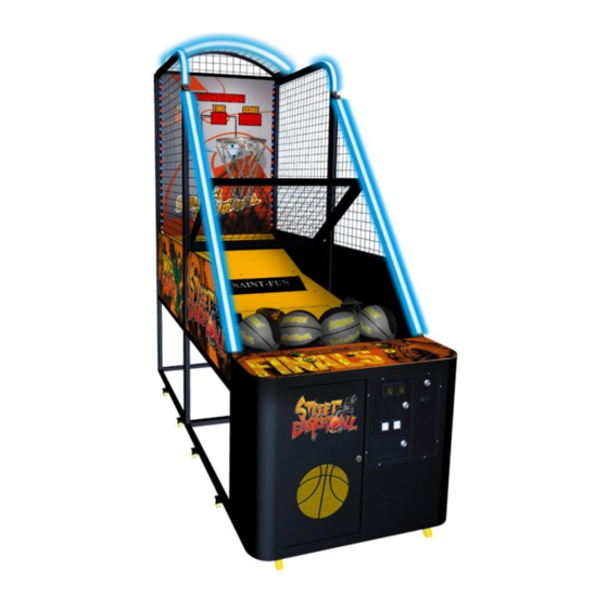
Page 6: Ii.machine View/Size And Power Rating
Position direction II.Machine view/size and power rating Machine Dimensions:W1030×D2500×Top cover H2643mm Weight:260 kg / 558.4 lbs (Accessories not Included ) (Top cover 6.6kg、Metal Shelf 3.4kg、Lower Side Net 4.2kg×4) Voltage:AC110V~120V/AC220V~240V(50/60Hz) Use Electrical plug display as a glide Located behind the machine. Power Consumption:200W Fuse:2A(AC220V~240V )/ 5A(AC110V~120V ) Token size:Ø... -
Page 7: Iv.assembly And Disassembly
IV.Assembly and disassembly 1. Assembly and disassembly for Disassembly type Step 1 : Screw【1B Basket kits】on the basket board front. Assembly parts 1A Sensor for basket 1B Basket kits 2A Basket board screw(M5×15)×6 nut(M5)×6 - 7 -... - Page 8 Step 2: 1. Screw 【2BR、2BL Back left & right net stander kits】 on basket board left and right. 2. Screw【2C Front net stander bridge(short)】on Back left & Right net stander kits. Insert position Assembly parts Basket board 2BR Back right net stander kit 2BL Back left net stander kit Front net stander bridge(short)
- Page 9 Step 3: Assemble 【3A、3B Front right & left net stander kit】 on basket board left and right, connect with screw & fixed it as drawing. Insert position Assembly parts 3A Front right net stander kit 3B Front left net stander kit screw (M8×70)×4 nut (M8)×4 - 9 -...
- Page 10 Step 4: Screw the 【BB、BF、FB、FF Base holders & Front net stander bridge(short)】 step by step as drawing. Assembly parts 2C Front net stander (short) bridge(short) 2E Front net stander (long) bridge(long) x2 4A Base holder BF 4B Base holder FB 4C Base holder FF 4D Base holder BB 4E Base holder FF...
- Page 11 Step 5: Screw the 【5A Wooden base A type、 5B Ball holder kit 、 5C Ball guide kits 、 6E Rubber pad】 step by step as drawing. Rubber pad Wooden base A type Rubber pad Ball holder kit Ball guide kits Assembly parts 5A Wooden base A type 5B Ball holder kit...
- Page 12 Step 6 : Connect the connectors on both sides, and pull the connectors of the bottom of side LED into main case. - 12 -...
- Page 13 Step 7: 1. Screw【6A Ball net holder kit】. 2. Screw【6B Main part】、【Metal Shelf (optional)】. Assembly parts 6A Ball net holder kit 6B Main part Metal Shelf (optional) Ball net holder kit Metal Shelf (optional) Main part Hexagonal Phillips screw with 2 Washers included 2 on each side.
- Page 14 Step 8: 1.Fix the 3 main cords as the following drawing. 2.Run the IC board plug and the ball holder kit plug located underneath the front of the ball net holder, through the hole in back of the main part. 3.Now connect plugs as shown in drawing.
- Page 15 Step 9 : Combine the connectors with the harness on main board. Step 10 : Screw【Top cover(optional)】step by step as drawing. Assembly parts Top cover(optional) screw (M5×38)×4 nut(M5)×4 - 15 -...
- Page 16 Step 11 : Connect the connectors of top cover and side LED. Step 12 : Cover the harness exposed and gap by wiring cover plate. Assembly parts Wiring cover plate x2 screw (M4×12)×4 wiring cover plate ×2 - 16 -...
-
Page 17: Assembly And Disassembly For Half-Assembly Type
2. Assembly and disassembly for Half-Assembly type Step 1: Turn the left and right frame180°to the position as drawing picture . Connect with screw & fixed it as drawing. screw (M8×70)×4 nut (M8)×4 - 17 -... - Page 18 Step 2: Screw the base frame FB and base frame FF as drawing picture. Assembly parts 4B Base holder FB 4C Base holder FF screw (M6×48)×2 nut (M6)×2 washer(M6.5×13.5)×2 screw (M6×26)×2 nut (M6)×2 washer(M6.5×13.5)×2 - 18 -...
- Page 19 Step 3: Screw the 5B Ball holder kit and 5C Ball guide kits as drawing picture. Assembly parts 5B Ball holder kit 5C Ball guide kits Ball holder kit Ball guide kits screw (M6×26)×12 nut (M6)×12 washer(M6.5×13.5)×12 - 19 -...
- Page 20 Step 4 : Connect the connectors on both sides, and pull the connectors of the bottom of side LED into main case. - 20 -...
- Page 21 Step 5: 1. Screw【6A Ball net holder kit】. 2. Screw【6B Main part】、【Metal Shelf (optional)】. Assembly parts 6A Ball net holder kit 6B Main part Ball net holder kit Metal Shelf (optional) Metal Shelf (optional) Main part Hexagonal Phillips screw with 2 Washers included 2 on each side.
- Page 22 Step 6: 1.Fix the 3 main cords as the following drawing. 2.Run the IC board plug and the ball holder kit plug located underneath the front of the ball net holder, through the hole in back of the main part. 3.Now connect plugs as shown in drawing.
- Page 23 Step 7 : Combine the connectors with the harness on main board. Step 8 : Screw【Top cover(optional)】step by step as drawing. Assembly parts Top cover(optional) screw (M5×38)×4 Nut(M5)×4 - 23 -...
- Page 24 Step 9: Connect the connectors of top cover and side LED. Step 10 : Cover the harness exposed and gap by wiring cover plate. Assembly parts Wiring cover plate x2 screw (M4×12) ×4 wiring cover plate ×2 - 24 -...
-
Page 25: Set-Up Position & Maintenance
3.【SET-UP Position & maintenance】 Fix position after assembly 1.Hoist the machine from the hoist point. 50CM(20’’) 2.Keep at least 50cm(20”) space from the back for maintenance and to avoid over heating. Electrical plug display Attention: ◎The power must be turned off before any movements. ◎Check the power rate before use AC110V~120V/AC220V~240V , epending on Outlet Label. -
Page 26: Link Adjustment
1.Link adjustment 【Cable link SET-UP】 The link set-up must follow DIP-SW-SEP-UP NO.1~15 machines. Intermittent allowed, but repeat is not allowed. A . Link up to 15 machines B . Only one main frame is needed. C . Any game could be used as the main frame. The link machines must Link Plug connect Link Plug... -
Page 27: Link Main Board Adjustment
【Link main board adjustment】 Multi-function button: 1.Press and start machine until LED display show 0 to enter LED Testing Mode. 2.In Standby Mode is「SERVICE」function, Press once means one coin, but No record. 3.In Audit Mode is「RESET」function. 4.In Ticket Dispenser Error Mode, is「Key out」function. -
Page 28: Adjustment
Link mode starting display: L I N E – T E S T _ _ _ C X X Program type(CXX type) Link mode station NO,(XX=1-15) When you turn on the main control machine, the other machines will link as set situation. 2.Adjustment Press and turn on the power, release the key after you hear the sound. -
Page 29: Set-Up 2】Additional Tickets
【SET-UP 2】Additional tickets M I N – O U T 0 ticket dispensed after every _ _ 2 _ _ 0 game is ended Press then release Each time game over _ _ 2 _ _ 1 Release 1 additional tickets Press then release Each time game over... -
Page 30: Set-Up 4】Game Time Set-Up
Press then release _ _ 3 _ 7 0 70 points:1 ticket Press then release _ _ 3 _ 8 0 80 points:1 ticket Press then release _ _ 3 _ 9 0 90 points:1 ticket Press then release _ _ 3 1 0 0 100 points:1 ticket The explanation:... -
Page 31: Set-Up 5】Basket Motor Auto Test
【SET-UP 5】Basket motor AUTO test STE–MOT-1 _ _ 5 _ _ _ Press then release to start basketball motor AUTO test (Warning alarm will start after 5 seconds, if there is an error) Press then release to enter SET-UP 6 【SET-UP 6】Ball holder motor AUTO test STE–MOT-2 _ _ 6... -
Page 32: Set-Up 9】Clear Credit
Press then release XXXXXX Displays Company logo _ _ 8 _ _ 1 DEMO music ON 【SET-UP 9】 Clear credit XXXXXX Displays Company logo _ _ 1 _ _9 Credit inserted Press then release XXXXXX Displays Company logo _ _ 0 _ _9 Credit is cleared... -
Page 33: Audit
4.AUDIT Press to enter audit system under standby function only. then release, to enter 【audit 1】 Press COUNT - IN Record total received coins, 1 C X X X X up to 999999 same as counter, counter reset is not allowed. Press then release, to enter【audit 2】... -
Page 34: Error Code
5.Error code Every time machine is turned on, it will do the AUTO test for 7 function points, before entering into standby function. The Error specification as below, Warning alarm action Left coin selector is disconnected C O I N – 1 【Error 1】... -
Page 35: Vi.how To Play
VI.How to play 1.There are 4 Stages in total A.Stage 1:Proceed to Stage 2,when the total scores are over 40 in the end. B.Stage 2:Proceed to Stage 3,when the total scores are over 150 in the end. C.Stage 3:Proceed to Stage 4,when the total scores are over 250 in the end. D.Stage 4:Final challenge, the last game will be finished when the time is terminated. -
Page 36: Vii.screw And Nut List
VII.Screw and Nut list Total picture Specification Position quantity screw (M5×15) Knock down machine Step 1 Knock down machine Step 10 screw (M5×38) Semi-assemble machine Step 8 Knock down machine Step 2.4 screw (M6×48) Semi-assemble machine Step 2 Knock down machine Step 4.5 screw (M6×26) Semi-assemble machine Step 2.3 Knock down machine Step 7... - Page 37 - 37 -...
Need help?
Do you have a question about the Street Basketball Deluxe LED and is the answer not in the manual?
Questions and answers