Advertisement
Advertisement
Table of Contents

Summary of Contents for AOX AOX-Q Series
- Page 1 AOX-Q ELECTRIC ACTUATOR The Instruction Book...
-
Page 2: Table Of Contents
General Safety Instructions Summary Performance Features Primary Technical Parameter Structure General Drawing Wiring Diagram Installation of Electric Actuators Debug Description 10. Running Test 11. Maintenance - 1 -... -
Page 3: Performance Features
If the power supply is 3 phase, should to check the rotating direction. 2. Summary "AOX-Q" series electric actuator is used for controlling 0° ~ 270° rotation of the valves and other similar products, such as butterfly valve, ball valve, damper, flapper valve, cock valve etc. It widely applies to petroleum, chemical, water treatment, shipping, paper making, power plant, heating, light industry and other industries. - Page 4 Set position accurately and conveniently, and not affected by excessive handle. 3.7.Torque Switch-- (Except AOX-Q-005/008/010) Providing overload protection to avoid the damage of valve and electric actuator when jammed by cutting power automatically.
-
Page 5: Primary Technical Parameter
4. Primary Technical Parameter 4.1 AOX-Q series electric actuator technical parameter Rated Current(A) Hand 60/50Hz Drive Output Operating Power wheel Weight Shaft Model single phase three phases Torque Time Revolution Size N·M 90° 110V 220V 380V 440V AOX-Q-005 18/22 Φ20 1.10/0.95... - Page 6 Asynchronous motor Limit switch 2×Open/ Close, SPDT,250VAC 10A Auxiliary limit switch 2×Open/ Close, SPDT,250VAC 10A Torque switch Close/Open, each 1, SPDT,250VAC 10A Except AOX-Q-005/008/010 Travel 90°±10° 0°~270° Fail safe/ Internal-placed thermal protection, Open 115℃ ±5℃/Close 97℃ ± 5℃ Operating temperature...
-
Page 7: Structure
4.3 Option Specification Option scheme Remark Explosion-proof actuator(Exd ⅡCT5) AOX-Q series Water-proof actuator (IP68,10M,250HR) AOX-Q series Potentiometer unit(1K-10K) AOX-Q series Proportion control unit (control signal 4-20mA DC/1-5V/1-10V) AOX-Q series Local control units (local control open/stop/close optional switch, local/remote AOX-Q series switch) Travel 120°, 180°,270°... -
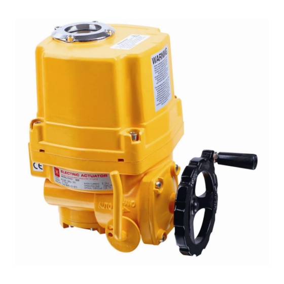
Page 8: General Drawing
6. General Drawing 6.1 AOX-Q-005~120 Appearance and installation dimension Picture 1 Unit: mm Model ΦA ΦB ΦD ΦF 4-M8 AOX-Q-005 Φ90 Φ70 Φ20 AOX-Q-008 4-M8 Φ90 Φ70 Φ20 AOX-Q-010 4-M8 Φ90 Φ70 Φ20 AOX-Q-015 4-M10 4-M8 Φ125 Φ102 Φ70 Φ22... - Page 9 6.1 AOX-Q-150~600 Appearance and installation dimension Picture 2 Unit:mm Model ΦA ΦB ΦD ΦF AOX-Q-150 4-M18 4-M16 Φ285 Φ165 Φ140 Φ45 AOX-Q-200 4-M18 4-M16 Φ285 Φ165 Φ140 Φ45 AOX-Q-300 4-M18 4-M16 Φ285 Φ165 Φ140 Φ45 AOX-Q-400 4-M18 4-M16 Φ285 Φ165 Φ140...
-
Page 10: Wiring Diagram
7. Wiring Diagram 7.1 AOX-Q-005~010 110/220VAC/50/60Hz,1Ph(on/off model) Picture 3 7.2 AOX-Q-015 ~ 600 110/220VAC/50/60Hz,1Ph ( on/off model ) Picture 4 - 9 -... - Page 11 7.3 AOX-Q-005~010 110/220VAC/50/60Hz,1Ph (modulating model) Picture 5 7.4 AOX-Q-015~600 110/220VAC/50/60Hz,1Ph (Standard modulating model) Picture 6 - 10 -...
- Page 12 7.5 AOX-Q-015~600 380V/440V AC/50/60Hz,3Ph (External standard on/off model) Picture 7 7.6 AOX-Q-015~600 110/220VAC/50/60Hz,1Ph (Intelligent on/off model) Picture 8 - 11 -...
-
Page 13: Installation Of Electric Actuators
8、Installation of Electric Actuators 8.1 Installation Sites 8.1.1 Notes for interior installation ◎Pls don’t install non-explosion-proof product to the place with explosive gas ◎When installing in the submerged or outdoor, please inform to us in advance ◎Please reserve space for cable repairing , manual operation. 8.1.2 Notes for outdoor installation ◎In order to avoid rain, direct sunlight and so on, a protective cover or enclosure IP68 is available ◎Please reserve space for cable repairing , manual operation. -
Page 14: Debug Description
8.3 Wire for Power 8.3.1 Remove the metallic plug and insert cables, pls use 3/4” explosion-proof joint in male thread or explosion-proof flexible tube. 8.3.2 If the joint is mismatch to the actuator, will result in destroying the sealing that can not meet the enclosure requirement. - Page 15 9.2 Adjustment of Travel Limit(see picture14) Move the electric actuator to the full-closed position by manual. And loosen locknut, turn cam (yellow open, red close) until touch close limit switch (CLS) , then screw locknut. It’s the way to set the full-closed travel limit position of electric actuator.
-
Page 16: Running Test
9.6 Proportion adjustable (PCU) Debug Description 9.6.1Technical parameters ① Input: —Input signal:4~20mADC; 2~10VDC; 0~5VDC 0~10VDC; 1~5VDC —Input resistance:250Ω —Feedback signal:100Ω~10KΩ ② Output: —Output signal:4~50mADC —Load resistance: Max 750Ω —Control output:Relay tip,250VAC,10A(Resistance load) ③ Resolution:Min 1/1000 ④ Adjustment of dead zone:0.1%~4.5% ⑤... -
Page 17: Maintenance
★NOTE ①Check wiring diagram, power supply, control signal. ②Don’t change the internal wiring. ③If the power supply is 3 phase, check the rotating direction. ④Enable the electric actuator lies in a half on/off position by manual, turn on electricity and input open signal. ⑤If the electric actuator runs to the open direction, the wiring is correct.
Need help?
Do you have a question about the AOX-Q Series and is the answer not in the manual?
Questions and answers