Advertisement
Quick Links
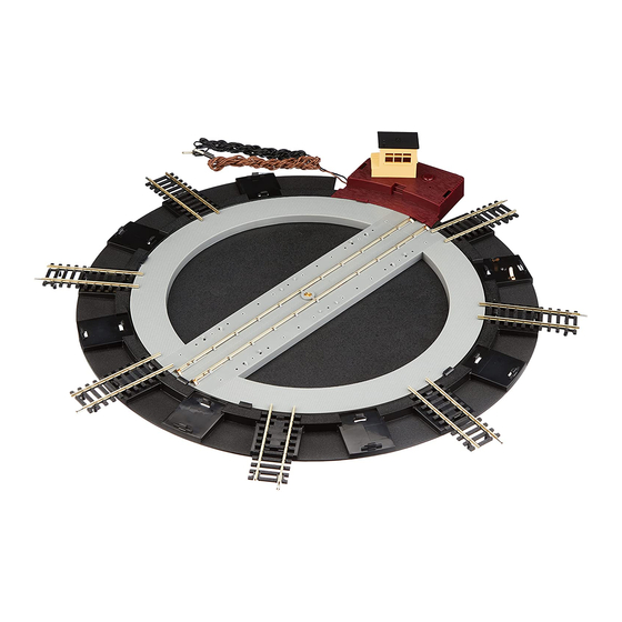
Electrically Operated Turntable
Direct adult supervision is required for children under 14 years
To ensure safe transit some parts of the Turntable are packed loose.
Please read right through these instructions before assembling and
operating the turntable.
Caution
a. Never attempt to turn the turntable bridge by hand.
b. When handling always use both hands – do not allow the turntable
base to twist or distort.
c. Always operate on a firm flat surface.
d. Fishplates have sharp edges. Handle with care.
Assembly
1. Inlet Ramp
The 'inlet' ramp has two electrical contacts (Fig.1). Clip one of the special
track sections to the ramp (Fig.2) ensuring that the underside of each
metal rail makes a good connection with the appropriate contact.
This ramp must always be fitted with track as electric power is supplied
through it to operate locomotives on all other turntable tracks.
2. Outlet Ramps
There are thirteen ramp positions to which the seven outlet track
sections may be fitted. These alternatives allow a turntable to be installed
within a comparatively small layout by selecting the most convenient
positions for them.
If using the outlets for storing locomotives DO NOT fit track sections
directly across the bridge from one another otherwise locomotives
stored in both positions will be energised together when the bridge is
aligned with them. Clip track sections to the selected ramps ensuring that
the rail ends overhanging the bridge will make good connections with the
bridge rail contacts (Fig.3).
3. Track Height
To provide room for the operating mechanism the track on the turntable
is a little higher than normal and the special track sections fitted to the
ramps are inclined slightly. This height variation can be minimised by
laying approach tracks on Hornby Track Underlay which should be laid at
double thickness for about 2 inches (50mm) from the end of the ramp.
4. Hand Rails
Fix a hand rail on each side of the bridge (Fig.4).
4
Turntable Bridge
1
Electrical Contacts
2
3
Special Track Section
Outlet Ramp
Hand Rails
12V
Special Track Section
1
3
/
" (82.5mm)
4
Inlet Ramp
Ensure good electrical
contact here
Bridge Rail
Contacts
Advertisement

Related Manuals for Hornby R070


Summary of Contents for Hornby R070
- Page 1 This height variation can be minimised by laying approach tracks on Hornby Track Underlay which should be laid at double thickness for about 2 inches (50mm) from the end of the ramp.
- Page 2 In the event of such damage, the set should not be used until the • Please retain these details and the address for future reference. Hornby Hobbies Limited, Westwood, Margate, Kent CT9 4JX, United Kingdom 4-680C 0907 Printed in China...
Need help?
Do you have a question about the R070 and is the answer not in the manual?
Questions and answers