Troy-Bilt CSV 060 Operator's Manual
Yard vacuum/chipper/shredder with vacuum/hose
Hide thumbs
Also See for CSV 060:
- Operator's manual (45 pages) ,
- Operation manual (40 pages) ,
- Specifications (1 page)
Advertisement
Available languages
Available languages
Quick Links
Safe Operation Practices • Set-Up • Operation • Maintenance • Service • Troubleshooting • Warranty
O
'
M
peratOr
s
anual
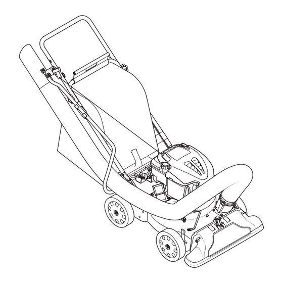
Yard Vacuum/Chipper/Shredder with Vacuum/Hose
Model CSV 060
WARNING
READ AND FOLLOW ALL SAFETY RULES AND INSTRUCTIONS IN THIS MANUAL
BEFORE ATTEMPTING TO OPERATE THIS MACHINE.
FAILURE TO COMPLY WITH THESE INSTRUCTIONS MAY RESULT IN PERSONAL INJURY.
NOTE: This Operator's Manual covers several models. Features may vary by model. Not all features in this manual are applicable to all
models and the model depicted may differ from yours.
TROY-BILT LLC, P.O. BOX 361131 CLEVELAND, OHIO 44136-0019
Form No. 769-11670
(May 20, 2016)
Advertisement

Related Manuals for Troy-Bilt CSV 060


Summary of Contents for Troy-Bilt CSV 060
- Page 1 NOTE: This Operator’s Manual covers several models. Features may vary by model. Not all features in this manual are applicable to all models and the model depicted may differ from yours. TROY-BILT LLC, P.O. BOX 361131 CLEVELAND, OHIO 44136-0019 Form No. 769-11670...
-
Page 2: Table Of Contents
If you have difficulty assembling this product or have any questions regarding the controls, operation, or maintenance of this machine, you can seek help from the experts. Choose from the options below: ◊ web: www.troybilt.com ◊ phone: (800) 828-5500 or (330) 558-7220 ◊ Write to Troy-Bilt LLC • P.O. Box 361131 • Cleveland, OH • 44136-0019... -
Page 3: Safe Operation Practices
Important Safe Operation Practices WARNING: This symbol points out important safety instructions which, if not followed, could endanger the personal safety and/or property of yourself and others. Read and follow all instructions in this manual before attempting to operate this machine. Failure to comply with these instructions may result HEED ITS WARNING! in personal injury. - Page 4 Maintenance & Storage Always refer to the operator’s manual for Notice Regarding Emissions proper instructions on off-season storage. Never tamper with safety devices. Check their Engines which are certified to comply with California If the fuel tank has to be drained, do this proper operation regularly.
-
Page 5: Assembly & Set-Up
Assembly & Set-Up Contents of Carton • Chipper/Shredder Vacuum (1) • Operator’s Manual (1) • Engine Operator’s Manual (1) • Upper and Lower Handle (1) • Hose Assembly (1) • Safety Glasses (1) • Bag (1) • Bottle of Oil (1) •... - Page 6 Adjustments Grasp bag handle with one hand and slide Nozzle Height locking rod on mounting bracket with other The nozzle can be adjusted to any six positions, hand toward engine. Use the end of mounting bracket as leverage when sliding the locking ranging from 5/8”...
-
Page 7: Controls & Operation
Controls & Operation Recoil Starter Hose Handle Hose Assembly Hose Extension Chipper Chute Nozzle/Hose Vac Lever Nozzle Nozzle Height Adjustment Lever Figure 4-1 Controls Operation Hose Assembly Used as an alternative to the nozzle to vacuum yard Starting & Stopping Engine WARNING: The operation of any waste such as leaves or pine needles. - Page 8 Using The Nozzle Vacuum Using The Hose Assembly Grasp bag handle with one hand and pull lock rod on mounting bracket with other hand Yard waste such as leaves and pine needles can be Place nozzle/hose vac lever in the bottom toward engine to release.
-
Page 9: Service
Service Maintenance Equipment Care Remove and clean the screen by scraping or washing with water. See Figure 5-3. • Clean the chipper/shredder vacuum General Recommendations thoroughly after each use. • Always observe safety rules when • Wash bag periodically with water. Allow performing any maintenance. - Page 10 Remove the flange lock nuts (a), front Carefully tilt and support the unit up The nuts (a) on the flat head cap screws wheels, and wave washers (b) that attach to provide access underneath to the can be reached from underneath using a to the pivot arm assemblies.
-
Page 11: Troubleshooting
Troubleshooting Problem Cause Remedy Engine Fails to start 1. Throttle lever (if equipped) not in correct 1. Move throttle lever to FAST or START position. starting position. 2. Move engine switch to ON position. 2. Engine switch (if equipped) in OFF position. 3. -
Page 12: Replacement Parts
Replacement Parts Component Part Number and Description BS-591868 Spark Plug (Briggs & Stratton) 951-14437 Spark Plug (MTD Engine) BS-491588S Air Filter Cartridge (Briggs & Stratton) BS-493537S† Pre-Cleaner (Briggs & Stratton) 951-14632 Air Cleaner Kit (MTD Engine) BS-799585 Fuel Cap (Briggs & Stratton) 951-14407 Fuel Cap Assembly (MTD Engine) BS-298090S†... - Page 13 Notes...
-
Page 14: Warranty
Troy-Bilt shall not be liable by Troy-Bilt for use with the product(s) covered by this manual will void for incidental or consequential loss or damage including, without your warranty as to any resulting damage. - Page 15 Medidas de seguridad • Configuración • Funcionamiento • Servicio • Solución de problemas • Garantía aNual del operador Aspiradora Para Patios — Modelo CSV 060 ADVERTENCIA LEA Y SIGA TODAS LAS INSTRUCCIONES DE ESTE MANUAL ANTES DE PONER EN FUNCIONAMIENTO ESTA MÁQUINA.
- Page 16 Elija entre las opciones que se presentan a continuación: ◊ Visite nuestro sitio web en www.troybilt.com ◊ Llame a un representante de Asistencia al Cliente al (800) 828-5500 ó (330) 558-7220 ◊ Escríbanos a Troy-Bilt LLC • P.O. Box 361131 • Cleveland, OH • 44136-0019...
- Page 17 Medidas importantes de seguridad ADVERTENCIA : La presencia de este símbolo indica que se trata de instrucciones importantes de seguridad que se deben respetar para evitar poner en peligro su seguridad personal y/o material y la de otras personas. Lea y siga todas las instrucciones de este manual antes de poner en funcionamiento esta máquina.
- Page 18 No modifique el motor Mientras alimenta material dentro de la No cambie la configuración del regulador máquina mantenga su rostro y su cuerpo del motor ni acelere demasiado el mismo. detrás y hacia un costado del canal de la El regulador controla la velocidad máxima Para evitar lesiones graves o la muerte, no modifique cortadora para evitar lesiones por retrocesos segura de operación del motor.
- Page 19 Montaje y Configuración Contenido de la caja • Aspiradora Para Patios (1) • Manual de Operador (1) • Manual de Operador de Motor (1) • Manija superior e inferior (1) • Montaje de la manguera (1) • Anteojos de seguridad (1) •...
- Page 20 Ajustes Bolsa Sostenga la manija de la bolsa con una mano Altura Del Pico y deslice la varilla de seguridad del soporte de montaje hacia el motor con la otra mano. Puede ajustar el pico en seis posiciones que varían Use el extremo del soporte de montaje como desde 5/8”...
- Page 21 Controles Y Funcionamiento Arrancador de Retroceso Bolsa Manija de la manguera Montaje de la manguera Extensión de Manguera Palanca del pico / Canal de la manguera de la cortadora aspiradora Palanca Palanca de ajuste de la altura del pico Figura 4-1 Controles Montaje de la manguera Funcionamiento...
- Page 22 Uso Del Pico De La Aspiradora Uso Del Montaje De La Manguera Tome la manija de la bolsa con una mano y tire de la varilla de seguridad del soporte de El desecho que se acumula en los patios como Coloque la manija del pico / manguera de la montaje hacia el motor con la otra mano para por ejemplo las hojas y las agujas de los pinos...
- Page 23 Servicio Mantenimiento NOTA: Saque la pantalla y límpiela con un cepillo o La limpieza con un chorro de agua a lávela con agua. Vea la Figura 5-3. presión no se recomienda, ya que el sistema Recomendaciones Generales de combustible podría resultar contaminado. Cuidados para el motor •...
- Page 24 Saque las tuercas de seguridad de brida, las Incline la unidad con cuidado y apóyela Es posible alcanzar las tuercas de los tornillos ruedas delanteras y las arandelas ondulatorias hacia arriba para obtener acceso por la parte de cabeza plana desde la parte inferior, que van unidas a los montajes del brazo inferior al material de montaje del pico y al mediante una llave universal de 1/2 pulg.
- Page 25 Solución de problemas Problema Causa Remedio El motor no arranca 1. La palanca del regulador (de ser equipado) no está 1. Mueva la palanca del regulador a la posición START (inicio)/RUN en la posición de arranque correcta. (dirigido). 2. Interruptor de motor (de ser equipado) en de 2.
- Page 26 Notas...
- Page 27 otas...
- Page 28 Troy-Bilt para usar con los productos a los productos, obligará a Troy-Bilt. Durante el plazo de la garantía incluidos en este manual anularán la garantía en lo que respecta a esos el único recurso es la reparación o reemplazo del producto como se...
Need help?
Do you have a question about the CSV 060 and is the answer not in the manual?
Questions and answers