Table of Contents
Advertisement
Quick Links
Section
1.
INDEX/PRESENTATION
2.
BASIC FUNCTIONAL DESCRIPTION
Sections for the installer
3.
DIMENSIONS
4.
INSTALLATION
4.1.
Placing the unit
4.2.
Connection placing
4.3.
Connection of units at 220 Vac
4.4.
Connection of units at 12 Vdc
4.5.
Connection of units at double voltage
4.6.
Earth terminal connection
4.7.
USB and RS485 connection links
4.8.
Extensions
4.9.
Maintenance
4.10.
Codification of inputs and outputs
4.11.
Installer's configuration
5.
TECHNICAL CHARACTERISTICS
6.
PARAMETERS
6.1.
Fertilization parameters
6.2.
Filter cleaning parameters
6.3.
General outputs parameters
6.4.
Sensor parameters
6.5.
Flow parameters
6.6.
Sector parameters
6.7.
Program parameters
6.8.
Communication parameters
6.9.
Various parameters
PRESENTATION
We wish to take this opportunity to thank you for the confidence in us which you have demonstrated in ex-
pressing interest or acquiring the AGRÓNIC 4000.
This confidence, for our part, stimulates our efforts to meet and surpass the expectations of our clients to jus-
tify the traditional quality of our products.
This manual will explain the specification of the equipment as well as its installation and use.
However, if after reading this you still have any doubts, contact us and we will happily answer them.
INSTRUCTION
MANUAL
INDEX
Theme
VERSION 3
Page
1
7.
PROGRAMS
2
8.
READINGS
8.1.
Total readings
8.2.
Anomaly readings
6
8.3.
History readings
6
8.4.
Sensor readings
6
8.5
Communication readings
7
8.6
Software versions
8
9.
ERASURE
10
10.
MANUAL
12
11.
CLOCK
14
12.
CONSULTATION
14
12.1.
General consultation
14
12.2.
Programs consultation
14
15
Notes
18
GENERAL SUMMARY
19
20
20
22
22
25
27
28
29
31
31
Sections for the user
1
32
35
35
36
37
37
38
38
38
38
39
40
40
41
42
43
Advertisement
Table of Contents

Related Manuals for Sistemes Electrònics Progrés s.a. AGRONIC 4000

Summary of Contents for Sistemes Electrònics Progrés s.a. AGRONIC 4000
- Page 1 INSTRUCTION MANUAL VERSION 3 INDEX Section Theme Page Sections for the user INDEX/PRESENTATION PROGRAMS BASIC FUNCTIONAL DESCRIPTION READINGS 8.1. Total readings Sections for the installer 8.2. Anomaly readings DIMENSIONS 8.3. History readings INSTALLATION 8.4. Sensor readings 4.1. Placing the unit Communication readings 4.2.
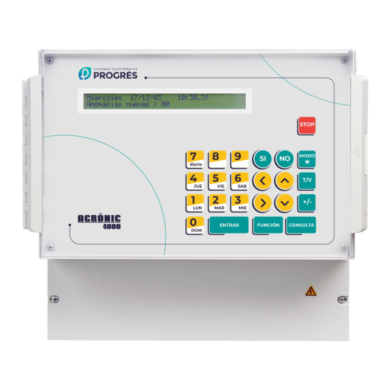
- Page 2 2. BASIC FUNCTIONAL DESCRIPTION The time or volume of application of every fertil- izer can be programmed independently for every sub- Electronic unit for the control of irrigation, fertiliza- program. tion, pH, pumping and filter cleaning, plus malfunction The use of mixers can be configured, with pre- detection and with the possibility of telemanaging the mixing and intermittent or non-stop mixing.
- Page 3 DETERMINING FACTORS configured as an anomaly that can in turn generate There are 4 determining factors which can affect an alarm or SMS message. The register has a ca- every one of the irrigation programs (“programs de- pacity of several weeks. The A-4000 only displays termining factors”...
- Page 4 Consultations of operations carried out by the EXTERNAL MODULES Agronics in 2 different ways, being able to pass from Capacity to connect with external modules of dif- one to the other by a simple movement of the mouse: ferent types: - By units: with different screens.
- Page 5 MODELS AND OPTIONS Model to “to built-in” a frame or “box” in a wall. Model with power supply at 230 Vac (115 Vac) or at 12 Vdc. Option for latch outputs (pulses) for two or three wires. ...
-
Page 6: Version
3. DIMENSIONS 4. INSTALLATION according to the measures in the section DIMEN- SIONS. It will be held with the screws of the corners, using the four pieces which are included in the unit. 4.1. PLACING THE UNIT The wardrobe must have a double isolation with protection for the operation relationship to the net Place the unit at the right position and height. - Page 7 4.2. CONNECTION PLACING In order to carry out the connections in the unit of enter the cables (do it with the connection cover on the “built-in” model, access the connectors placed at and screwed, in order to avoid possible malfunctions). the back.
-
Page 8: Connection Of Units At 220 Vac
4.3. CONNECTION OF UNITS AT 220 Vac The unit has to be installed following the prevail- ing regulations for electrical installations. The unit will not be completely protected if it is not used according to the information given in the manual. The unit has to be placed in such a way that the elements which may get interferences, such as the sensor inputs, the sensor power supply, the links to... - Page 9 Every output can be assigned to an irrigation sec- tion of “Parameters - Sectors” or “Parameters - tor (one or more electrovalves) or to a general output Generals”. (pumps, filters, mixers, etc.). To do so, go to the sec- Example of connection :...
- Page 10 4.4. CONNECTION OF UNITS AT 12 Vdc “Digital inputs (D)”. This is done by connecting one contact pole to the corresponding input and the other The unit has to be installed following the prevail- pole to the “NEGATIVE” of battery. ing regulations for electrical installations.
- Page 11 Example of connection in conventional unit at 12 Vdc : Example of connection in unit at 12 Vdc with diesel engine control :...
-
Page 12: Connection Of Units At Double Voltage
4.5. CONNECTION OF UNITS AT DOUBLE VOLTAGE The unit has to be installed following the prevail- ing regulations for electrical installations. The unit will not be completely protected if it is not used according to the information given in the manual. The unit has to be placed in such a way that the elements which may get interferences, such as the sensor inputs, the sensor power supply, the links to... - Page 13 Example of connection in unit with “double voltage in outputs” : Example of connection in unit with “double voltage in outputs” and with diesel engine control :...
-
Page 14: Extensions
4.6. EARTH TERMINAL CONNECTION 4.9. MAINTENANCE The “built-in” model has a terminal screw to con- 4.9.1. Fuses nect the protection earth terminal (in the “box” model In order to replace the fuses it is necessary, for it is not necessary as it has not got a metallic casing). precaution, to disconnect the unit from the general A pressed terminal will be applied to the cable when mains, half turn the cover of the fuse holder and insert... -
Page 15: Codification Of Inputs And Outputs
4.10. CODIFICATION OF INPUTS AND OUTPUTS Both the analog and digital sensor inputs as well as the digital outputs (relays) are coded using an 8-digit number that indicates its physical location. Following tables are shown to help code them. 4.10.1. Digital sensor inputs Device Module Sensor... - Page 16 4.10.5. Charts to write down of outputs to generals and sectors : PUMPS ALARMS Pump 1 Alarm 1 Pump 2 Alarm 2 Pump 3 Alarm 3 Pump 4 FERTILIZERS Fertilizer general output Fertilizer 1 Analog output F1 Fertilizer 2 Analog output F2 Fertilizer 3 Analog output F3 Fertilizer 4...
- Page 17 AUXILIARY AUXILIARY Sensor digi. Sensor digi. SECTOR OUTPUT SECTOR OUTPUT Output Flow detector Output Flow detector...
- Page 18 4.11. INSTALLER’S CONFIGURATION In parallel and proportional fertilization, the pul- ses that occur as the proportion ends may be This programming operation is only done by the counted (useful when the time between pulses is installer the first time the equipment has been started less than two seconds).
- Page 19 5. TECHNICAL CHARACTERISTICS Power supply Units for alternating current Units for direct current Tension 230 Vac or 115 Vac +5 % -10 % CAT II 12 Vdc +10 % -5 % = = = Frequency 50-60 Hz Energy consumption Below to 43 VA Below to 18 W (at rest 1.7 W) Fuses Input...
- Page 20 6. PARAMETERS grams, the total quantity of water and fertilizer to be applied to the crop will be programmed. In order to install the unit, it is necessary to enter in the section of “Parameters” to adapt it to the par- Proportion series : ticular necessities of each installation.
- Page 21 The pre-irrigation and the post-irrigation are inde- For uniform fertilization, the flow for each fertilizer pendently programmed in each program. is entered in liters / hour. The way of acting of the proportional modality is Fertilizer flow (l/h) : the next: the pre-fixed pre-irrigation is done, it applies F1 083.00 F2 083.00 F3 025.00 the programmed water/fertilizer proportion, when the fertilizer units conclude, it will wait until the irrigation...
-
Page 22: Filter Cleaning Parameters
6.2. FILTER CLEANING PARAMETERS Answering affirmatively to the “Stop sectors when cleaning” request, the sectors which have common The filters cleaning is another important service of the Agrónic range which allows to clean periodical irrigation pumps assigned with those assigned to the and automatically the four possible groups of filters by filters cleaning will temporary stop. - Page 23 An output relay has to be assigned to each An auxiliary output may be assigned for each of pump. In case of avoiding the use, leave the value at the fertilizers. The output number of the relay may be common for various auxiliaries, with which for example The start temporization corresponds to the time can be obtained different fertilizers.
- Page 24 When the use is required, the correspondent out- more time than necessary to carry out this stoppage puts will be assigned in the unit. procedure. Alarm Pre-heating time : 000” Output : 00000000 00000000 00000000 Stop time : 035” The time between start-up and pumping corre- The alarm outputs activate when an event occurs sponds to the time the system waits from when the that has an alarm configured with an activation setting.
-
Page 25: Sensor Parameters
[ values for pH / EC control option ] Code 22: Fertilizer meter 8, pulses [ values for Pressure regulation option ] -Pulse value: 0100 cl -Maximum time between pulses: 200” Code 23: Irrigation meter 1, frequency 6.4. SENSOR PARAMETERS ... - Page 26 When a malfunction has taken place and then it The Agrónic 4000 allows us, as well, to work with has been repaired, the “Manual Function” has to be the irrigation meter by frequency, asking for the used in order to finish it and continue with the irriga- cycles per liter the meter sends.
-
Page 27: Flow Parameters
If it is necessary to correct the reading from a ANALOG SENSOR PARAMETERS sensor, a tare value can be entered: a positive one to Sensor: 1 Format : 2 add to the sensor value and a negative one to subtract from it. -
Page 28: Sector Parameters
With "it does not stop (0)" it will only record the Each sector can be assigned to one or more anomaly. among the four “P1234” pumps and among the four “SF1234” digital sensors with stop function. When With "temporary (1)" it will also cancel, in a entering “YES”... -
Page 29: Program Parameters
6.7. PROGRAM PARAMETER This takes place in two stages: 1. At “Parameters – Programs” the determining First of all, the program number has to be cho- factors that can affect the program and how sen. the determiner will be dealt have to be indi- cated. - Page 30 The “calculation reference” is used to define an P01 Det.factor 2, type : 05 integration point of reference above which the value modification factor which surpasses the reference will Sensor : 16 Temporary (Y/N): NO be applied. P01 Det.factor 2, type : 05 P01 Det.factor 4, type : 07 Reference : 034 Km/h Reference for calculation : 02000 Wh/m...
-
Page 31: Communication Parameters
After entering a number in the PIN code, the theft P01 Det.factor 4, type: 10 protection is activated. If Agrónic is above 10' without Reference for calculation : + 0.80 mm/d power supply, it will require the PIN code to be fed again. - Page 32 7. PROGRAMS To accede to the irrigation programming press Programs : Readings : 2 Erasure : 3 the “Function” key, choose number 1 and then press Parameters: 4 Manual : Clock : "Enter". Look at an example of a program resume: The Agrónic 4000 has 35 independent programs The values of a program are the next: with 12 sub-programs or irrigation sequences at each...
- Page 33 In order to postpone the irrigation some days, a to be pressed when the cursor is at the start va- variation would, for example, irrigate in alternate days lue. but waiting initially 8 days: “Frequency 02(08)”, once 8 days have been taken away, the meter will take the P03-00 SMTWTFS Start= 083.5 cbar...
- Page 34 Look at examples of determining factors: At the first line the sector or sectors to be acti- vated are asked. Each sub-program has the possibility o F=+07% 0.75 mm/d, increase the irrigation a to accept up to a maximum of 10 sectors or irrigation 7 % per each 0.75 millimeters/day of crop valves.
- Page 35 second 13 liters, deciliters or centiliters of “fertilizer 2” 8.1. TOTAL READINGS per each 8 m of water. At “Parameters - Flows” the At the “Totals” the water and fertilizers units ap- units these proportions will be used with are identified. plied by time and volume are shown, in general and in The irrigation units of the ratio are in time or vol- each sector.
- Page 36 8.2. ANOMALY READINGS paired, enter in “Function - Manual - Malfunctions” to reactivate at the same point where it stopped. The anomalies are incidences that are recorded in the memory and which can be read at the “Read- Fertilizer without control malfunction ings - Anomalies”...
- Page 37 is not correct, causing that the programs that are SMS messages communication a.[N48][AL-1][ - ] working with sectors assigned to the sensor stop and GPRS modem communication a. [N 63] [ - ] [ - ] it continues with the following ones in the sequence of ...
-
Page 38: Table Of Contents
Among the 40 possible, the number of sensor is 10. MANUAL shown in the first line, and at its right the instant value By using the manual function, the following can with the sensor units. Where the sensor is connected be done: to is shown in the second line. -
Page 39: Function" Key, Choose The Function By Its Number
Before the out of service is carried out, the con- 11. CLOCK firmation will be asked, yet once it is done the values The CLOCK function will be used to set on the in- of the irrigation that is taking place are cancelled from ternal clock of the Agrónic 4000. - Page 40 12. CONSULTATION There is a “General consultation” and a “Pro- gram consultation”, and to move between them, To go into this section press the “View” key. We press the left and right arrows. To move through the will find detailed information about what the controller screens in each group, press the up and down keys.
- Page 41 The same occurs with the sectors when more than 8 are activated at a time. 06.8 pH Ref.= 06.7 pH (045%) 02.1 mS In the lower one it shows the general outputs ac- 03.5 bars Ref.= 03.5 bars (075%) tivated, starting by the pumps (P1234), fertilizers (F12345678 FC), mixers (M12345678) and the filters.
- Page 42 When the fertilization is proportional the format is respective signs, the result is what we see on this “00/00”, in this way, each fertilizer has two values, an consultation screen. irrigation units one at the left of the bar and the fertil- The values of the second line depend on the type izer one at the right of the bar.
- Page 43 CONSULTATION SCREENS General malfunction Flow malfunction Irrigation meter malfunction VIEW No control fertilizer malfunction pH regulation malfunction Conductivity control malfunction OUT OF SERVICE IN STOP General consultation Sub-program Pre-irrigation Programs consultation proceeding Date / New Anoma- P01-08 Pre.= 00:05 Monday 22/09/14 18:49.33 lies / Mal- I= 02:18...
-
Page 44: Erasure Program
FUNCTIONS SCREENS SMTWTFS Start= 23:45 Frequency =02(00) Start= 99:03 FUNCTION Activa.=05—01:12 I.=08400 Wh/m READINGS Totals : 1 Anomalies : 2 New anomalies : 3 History: 4 Sensors: 5 READINGS Communica.: 6 Versions: 7 P01-00 SM. WT. S Start =23:45 Pre/Pos=005/012 F=+05% 01/05 to 15/07 P01-01 S08 09 12 23 .. -
Page 45: General
PARAMETERS Programs : 1 Readings: 2 Erasure: 3 PARAMETERS Fertiliza.: 1 Cleaning: 2 PARAMETERS Sectors: 6 Programs: 7 SCREEN FUNCTION Parameters: 4 Manual: 5 Clock: 6 Generals: 3 Sensors: 4 Flows: 5 Communica.: 8 Various: 9 Fertilizer parameters 1 Flow parameters 5 Fert. - Page 46 PARAMETERS SCREENS PARAMETERS Fertiliza.: 1 Cleaning : 2 PARAMETERS Sectors : 6 Programs : 7 Generals : 3 Sensors : 4 Flows : 5 Communica. : 8 Various Digital sensor parameters 4.1 ---> Code 26: Irrigation meter 4, frequency Analog sensor parameters 4.2 -Cycles per litre: 009.43 Hz Function code number: 00 Sensor number: 02...
- Page 47 PARAMETERS SCREENS PARAMETERS Fertiliza.: 1 Cleaning: 2 PARAMETERS Sectors: 6 Programs: 7 Generals: 3 Sensors: 4 Flows: 5 Communica.: 8 Various: 9 Sectors parameters 6 Programs parameters 7 Communication parameters 8 Sectors 1 to 99 Programs 1 to 35 PC: 1 Output relay: 00000001 Irrigation group: 1 SMS: 2...
-
Page 48: Program
READING SCREEN READINGS Totals: 1 Anomalies: 2 Programs: 1 Readings: 2 Erasure: 3 FUNCTION New anomalies: 3 History: 4 Sensors: 5 Parameters: 4 Manual: 5 Clock: 6 READINGS Communica.: 6 Versions : 7 Totals Last erasure History from 20 date History to 50 days 20/09/14 P= 01 02 03 04 05 06 07 08 09 10...
Need help?
Do you have a question about the AGRONIC 4000 and is the answer not in the manual?
Questions and answers