
Subscribe to Our Youtube Channel
Related Manuals for Shizuoka Seiki VAL6 MPX5


Summary of Contents for Shizuoka Seiki VAL6 MPX5
-
Page 1: Table Of Contents
Service Manual Contents Names of components Safety Devices Specifications Wiring Diagam 5. Sequence Time Chart Troubleshooting Standard resistance & Voltage Check & Repair 2014.08... -
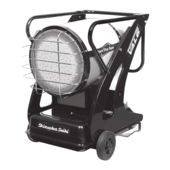
Page 2: Names Of Components
Names of components ★ Burner Section... -
Page 3: Safety Devices
★ Switch Section Safety Devices When the flame is extinguished, turn『OFF』the operating switch. Then turn『ON』the operating switch again after the problem is solved. -
Page 4: Specifications
Specifications Model Type VAL6MPX5 VAL6MPX1 Type Radiated/Direct-fired Ignition System High intensity discharge Fuel #1DIESEL(KEROSENE) High : 0.48GAL/h , 1.55kg/h High : 1.8L/h , 1.55kg/h Fuel Consumption Low : 0.42GAL/h , 1.38kg/h Low : 1.6L/h , 1.38kg/h High : 62,500BTU , 18kW High : 15,800kcal/h , 18kW Heat Output Low : 55,500BTU , 16kW... -
Page 5: Sequence Time Chart
Sequence Time Chart Plug Switch Switch Ignition Operation Switch Fan Motor Igniter Fuel Pump Flame Monitor Blower Fan Solenoid Valve Fuel pre-heater within 5sec 10sec 10sec 200sec pump delay post ignition post purge ※Fuel pre-heater : Operating when the temperature in the inside of burner cover falls below 41 degrees Fahrenheit (5 degrees Celsius) and stopping when it reach over 68 degrees Fahrenheit (20 degrees Celsius). -
Page 6: Troubleshooting
Troubleshooting Phenomenon page The lamp does not light on The heater does not start Operation lamp is lit Misfire lamp is lit Fuel pump does not operate at all No fuel or a little fuel is pumped up The heater does not ignite (though the heater is working) Igniter does not spark. - Page 7 VAL6 MPX5/MPX1 Troubleshooting Phenomenon Possible Cause How to check Result Remedy No power source supplied Measure voltage of AC outlet. If circuit tester indicates 0V, power Connect power source 1.The heater does The lamp does not Standard: source is disconnected not start.
- Page 8 VAL6 MPX5/MPX1 Troubleshooting Phenomenon Possible Cause How to check Result Remedy Loose connection of fuel pump Plug in fuel pump connector (CN 6) If it works normally, fuel pump Plug in connector (CN 6) firmly 2.The heater does Fuel pump does not...
- Page 9 VAL6 MPX5/MPX1 Troubleshooting Phenomenon Possible Cause How to check Result Remedy Loose flame monitor Open burner cover, and check if the If flame monitor comes off, it Put in flame monitor firmly 3.Misfire within 10 Misfire lamp is lit. flame monitor is in doesn't work seconds after ignition.
- Page 10 VAL6 MPX5/MPX1 Troubleshooting Phenomenon Possible Cause How to check Result Remedy Absorbing air into fuel lines Check looseness of each joint If any joint is loose, air is absorbed Fasten joints more tightly 4.Combustion stops Misfire lamp is lit. from joints into fuel lines from loose joint during operation.
- Page 11 VAL6 MPX5/MPX1 Troubleshooting Phenomenon Possible Cause How to check Result Remedy Shortage of combustion air Check extent of combustion air inlet If combustion air inlet is too small, Extend combustion air inlet 6.Smoke comes out. opening it burns in short of Oxygen opening.
- Page 12 VAL6 MPX5/MPX1 Troubleshooting Phenomenon Possible Cause How to check Result Remedy If either of the values is 0Ω, Short circuit of transformer coil Unplug transformer connector (CN 7) Replace a transformer 9.Fuse blows out When the plug is put from burner controller, then measure transformer is short-circuited into the outlet.
-
Page 13: Standard Resistance & Voltage
Standard resistance & Standard Voltage ★Standard resistance of functional parts Resistance Connector No Parts Lead Condition Memo MPX5 MPX1 0Ω Operating Switch 1-2PIN Red-Red ∞Ω 0Ω change-over Switch 4-5PIN White-White ∞Ω 0Ω not in working Overheat Protection 1-2PIN Red-Red ∞Ω in working CN13 0Ω... - Page 14 ★Input &Output of Burner Control Voltage Connector No Parts Lead Condition Memo MPX5 MPX1 Black - White (MPX5) Power Cable AC 120V (±10%) AC 230V (±10%) Brown - Light Blue (MPX1) Red - White input AC 120V (±10%) AC 230V (±10%) Transformer output about AC 15V...
-
Page 15: Check & Repair
Check & Repair Figure 1 Removing a burner cover Figure 2 Removing a burner unit Figure 3 Mesuring resistance Figure 4 Mesuring voltage Figure 5 Checking a surge absorber (SA1) Figure 6 Replacing a fuse Figure 7 Checking a filter element Figure 8 Checking a fuel tank Figure 9... - Page 16 Removing a burner cover Figure 1 Unscrew two screws and take burner cover off Burner cover Screws Removing a burner unit Figure 2 Unscrew three nuts as below and take the burner unit off Nuts...
- Page 17 Mesuring resistance Mesuring voltage Figure 3 Figure 4 ① ① Unplug an intended connector from Operate the heater burner controller ② ② Turn on the multimeter and set Turn on the multimeter and set AC multimeter range voltage range (partially direct current range) ③...
- Page 18 Replacing a fuse Figure 6 Be sure to unplug the power plug then open the fuse cap and Check whether fuse is blown out Fuse cap Checking a filter element Figure 7 Check whether or not the filter element is dirt or foul In case the filter element is dirty, replace it with a new one...
- Page 19 Checking a fuel tank Figure 8 Checking a fuel pump Figure 9 Take out a fuel outlet line then check whether or not fuel comes out CAUTION: Fuel will squirt cheerfully Fuel outlet line...
- Page 20 Positioning a electrode Figure 10 Take out a burner and check each clearance as below Tip of electrode Observation Manufacturer does not recommend to fix electrode as they are very sensitive to position, so it is recommended to replace it. Cleaning a frame monitor Figure 11...
- Page 21 Checking a burner cone and whirl vane Figure 12 Take out a burner and check whether or not burner cone and whirl vane are dirt or not. In case the burner cone and/or whirl vane is dirty, clean it(them) with cloth or brush.
- Page 22 Adjusting an air inlet opening of fan motor Figure 13 Unscrew a decorative screw and then extend/narrow an air inlet opening. Also trial operation is required after each adjustment. Be sure to repeat adjustment until following symptoms are identified. ・ Heater ignites within one second after pump starts to operate ・...
- Page 23 Checking a pre-heater Figure 14 ①Unplug the connector of pre-heater ②Measure resistance of the pre-heater between A and B. (see below graphic illustration) Standard resistance: 735Ω Connectors Thermostat Graphic illustration Pre-heater Burner control Connectors Thermostat...
Need help?
Do you have a question about the VAL6 MPX5 and is the answer not in the manual?
Questions and answers