Table of Contents
Advertisement
Quick Links
Advertisement
Table of Contents

Subscribe to Our Youtube Channel
Summary of Contents for Linx Technologies RM Series
- Page 1 RM Series GPS Receiver Module Data Guide...
-
Page 2: Table Of Contents
Table of Contents Warning: Some customers may want Linx radio frequency (“RF”) products to control machinery or devices remotely, including machinery or devices that can cause death, bodily injuries, and/or property Description damage if improperly or inadvertently triggered, particularly in industrial Features settings or other applications implicating life-safety concerns (“Life and Property Safety Situations”). -
Page 3: Description
Housed in a compact reflow-compatible SMD package, the receiver requires no programming or additional RF components (except an antenna) to form a complete GPS solution. This makes the RM Series easy to integrate, even by engineers without previous RF or GPS experience. -
Page 4: Ordering Information
= 3.3V, without active antenna, position fix is available Standby 0.135 = 0V Backup Battery Voltage No pull-up or pull-down on the lines Relative to other RM Series modules, not to UTC time Backup Battery Current µA Figure 4: Electrical Specifications – –... -
Page 5: Pin Assignments
VBACKUP A GPS receiver receives and times the signals sent by multiple satellites Figure 5: RM Series GPS Receiver Pinout (Top View) and calculates the distance to each satellite. If the position of each satellite is known, the receiver can use triangulation to determine its position Pin Descriptions anywhere on the earth. -
Page 6: Time To First Fix (Ttff)
VBACKUP 11 The module’s high-performance RF architecture allows it to receive GPS signals that are as low as –161dBm. The RM Series can track up to 22 satellites at the same time. Once locked onto the visible satellites, the Figure 7: Supply Filter receiver calculates the range to the satellites and determines its position and the precise time. -
Page 7: The 1Pps Output
Antenna Considerations The 1PPS line outputs 1 pulse per second on the rising edge of the GPS The RM Series module is designed to utilize a wide variety of external second when the receiver has an over-solved navigation solution from five antennas. -
Page 8: Slow Start Time
Slow Start Time Interfacing with NMEA Messages The most critical factors in start time are current ephemeris data, signal Linx modules default to the NMEA protocol. Output messages are sent strength and sky view. The ephemeris data describes the path of each from the receiver on the TX line and input messages are sent to the receiver satellite as they orbit the earth. -
Page 9: Nmea Output Messages
NMEA Output Messages GGA – Global Positioning System Fix Data Figure 9 contains the values for the following example: The following sections outline the data structures of the various NMEA messages that are supported by the module. By default, the NMEA $GPGGA,053740.000,2503.6319,N,12136.0099,E,1,08,1.1,63.8,M,15.2,M,,0000*64 commands are output at 9,600bps, 8 data bits, 1 start bit, 1 stop bit, and Global Positioning System Fix Data Example... - Page 10 GLL – Geographic Position – Latitude / Longitude Mode 1 Values Figure 11 contains the values for the following example: Value Description $GPGLL,2503.6319,N,12136.0099,E,053740.000,A,A*52 Manual – forced to operate in 2D or 3D mode Geographic Position – Latitude / Longitude Example Automatic –...
- Page 11 RMC – Recommended Minimum Specific GPS Data VTG – Course Over Ground and Ground Speed Figure 15 contains the values for the following example: Figure 16 contains the values for the following example: $GPRMC,053740.000,A,2503.6319,N,12136.0099,E,2.69,79.65,100106,,,A*53 $GPVTG,79.65,T,,M,2.69,N,5.0,K,A*38 Recommended Minimum Specific GPS Data Example Course Over Ground and Ground Speed Example Name Example...
-
Page 12: Input Messages
Input Messages ZDA – Universal Time and Date Figure 17 contains the values for the following example: The following outlines the serial commands input into the module for configuration. There are 3 types of input messages: commands, writes and $GPZDA,183746.000,22,08,2014,,*56 reads. - Page 13 The write and read messages are shown in Figure 21. A write message 101 – Hot Re-start triggers an acknowledgement from the module. A read message triggers a This command instructs the module to conduct a hot re-start using all of response message containing the requested information.
- Page 14 220 – Position Fix Interval 251 – Serial Port Baud Rate This command sets the position fix interval. This is the time between when This command sets the serial port baud rate. the module calculates its position. Serial Port Baud Rate Command and Response Position Fix Interval Command and Response Command Command...
- Page 15 255 – Sync 1PPS and NMEA Messages 285 – 1PPS Configuration This command enables or disables synchronization between the 1PPS This command configures the 1PPS output. pulse and the NMEA messages. When enabled, the beginning of the 1PPS Configuration Command and Response NMEA message on the UART is fixed to between 170 and 180ms after the Command rising edge of the 1PPS pulse.
- Page 16 286 – Enable Active Interference Cancellation Set NMEA Output Messages This command enables or disables active interference cancellation. This This configures how often each NMEA output message is output. feature helps remove jamming and narrow-band interference to enable a NMEA Output Messages Command and Response position fix.
- Page 17 Set Datum Static Navigation Threshold This configures the current datum that is used. This configures the speed threshold to trigger static navigation. If the measured speed is below the threshold then the module holds the current Set Datum Command and Response position and sets the speed to zero.
-
Page 18: Typical Applications
Ephemeris Prediction EASY™ is a function to generate orbit predictions for faster cold and warm Figure 35 shows the RM Series GPS receiver in a typical application using starts. It does this without the need for Internet connectivity or assistance a passive antenna. -
Page 19: Master Development System
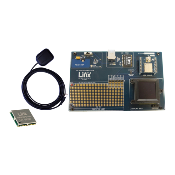
Master Development System Microstrip Details The RM Series Master Development System provides all of the tools A transmission line is a medium whereby RF energy is transferred from necessary to evaluate the RM Series GPS receiver module. The system one place to another with minimal loss. This is a critical factor, especially in... -
Page 20: Board Layout Guidelines
Board Layout Guidelines Each of the module’s ground pins should have short traces tying immediately to the ground plane through a via. The module’s design makes integration straightforward; however, it is still critical to exercise care in PCB layout. Failure to observe good Bypass caps should be low ESR ceramic types and located directly layout techniques can result in a significant degradation of the module’s adjacent to the pin they are serving. -
Page 21: Production Guidelines
Production Guidelines Reflow Temperature Profile The single most critical stage in the automated assembly process is the The module is housed in a hybrid SMD package that supports hand and reflow stage. The reflow profile in Figure 44 should not be exceeded automated assembly techniques. -
Page 22: Appendix A
Appendix A RM Series GPS Receiver Supported Datums The following datums are supported by the RM Series. Number Datum Region Astro Dos 71/4 St Helena Island RM Series GPS Receiver Supported Datums Astro Tern Island (FRIG) 1961 Tern Island Number... - Page 23 RM Series GPS Receiver Supported Datums RM Series GPS Receiver Supported Datums Number Datum Region Number Datum Region European 1950 Italy (Sardinia) Ireland 1965 Ireland European 1950 Italy (Sicily) ISTS 061 Astro 1968 South Georgia Islands European 1950 Malta ISTS 073 Astro 1969...
- Page 24 RM Series GPS Receiver Supported Datums RM Series GPS Receiver Supported Datums Number Datum Region Number Datum Region Canada (New Brunswick, Ordnance Survey Great Britain 1936 England North American 1927 Newfoundland, Nova Scotia, Quebec) Ordnance Survey Great Britain 1936 England, Isle of Man, Wales...
- Page 25 RM Series GPS Receiver Supported Datums RM Series GPS Receiver Supported Datums Number Datum Region Number Datum Region Santo (Dos) 1965 Espirito Santo Island WGS 1984 Global Definition Sao Braz Azores (Sao Miguel, Santa Maria Ids) Yacare Uruguay Sapper Hill 1943...
- Page 26 For more complex RF solutions, Apex Wireless, a division of Linx Technologies, creates optimized designs with RF components and firmware selected for the customer’s application. Call +1 800 736 6677 (+1 541 471 6256 if outside the United States) for more information.
- Page 27 Under no circumstances shall any user be conveyed any license or right to the use or ownership of such items. ©2016 Linx Technologies. All rights reserved. The stylized Linx logo, Wireless Made Simple, WiSE, CipherLinx and the stylized CL logo are trademarks of Linx Technologies.
Need help?
Do you have a question about the RM Series and is the answer not in the manual?
Questions and answers