
Summary of Contents for fafnir VISY-Command (VI-4)
- Page 1 Technical Documentation VISY VISY-Command (VI-4) Version: Edition: 2019-02 Art. no.: 207184 FAFNIR GmbH • Schnackenburgallee 149 c • 22525 Hamburg • Tel.: +49 / 40 / 39 82 07-0 • Fax: +49 / 40 / 390 63 39...
-
Page 2: Table Of Contents
Table of contents Introduction ....................1 Related documentation ..........................2 Requirements for service engineers ....................2 Safety instructions ............................3 Versions of the VISY-X system ..............4 Wired version ............................... 4 Wireless version / radio system ......................4 VISY-Command ..................5 Design and function .......................... - Page 3 EU-Type Examination Certificate VP-1, VP-2 and VP-4 ............. 23 11.4.1 Instructions VP-… ............................. 26 © Copyright: Reproduction and translation are permitted only with the written consent of the FAFNIR GmbH. FAFNIR GmbH reserves the right to carry out product alterations without prior notice. Table of contents...
-
Page 4: Introduction
Introduction The VISY-X system (Volume Information SYstem) provides highly precise and continuous level measurements for all commercially available fuels in up to 16 tanks. Simultaneously the product temperature and the water level at the bottom of the tank are measured. The system includes: VISY-Command (central unit) •... -
Page 5: Related Documentation
Related documentation Before configuring and operating the VISY-Command central unit, the level and environmental sensors must be installed and connected to it. The VISY-Command is then configured with the VISY-Setup software via a PC or notebook. Please also observe the additional instructions in the following technical documentation: ... -
Page 6: Safety Instructions
Safety instructions The VISY-X system is optimised for use in petrol stations and is compatible with all commer- cially available fuels. It serves to measure and evaluate the filling levels in tanks. The system must be used exclusively for this purpose. Observe and follow all product safety notes and operating instructions. -
Page 7: Versions Of The Visy-X System
Versions of the VISY-X system Two versions of the VISY-X system are available which differ in different data transmission technology: The wired version The wireless version / radio system Wired version In most cases, data is transferred between the sensors and the VISY-Command central unit via cable. -
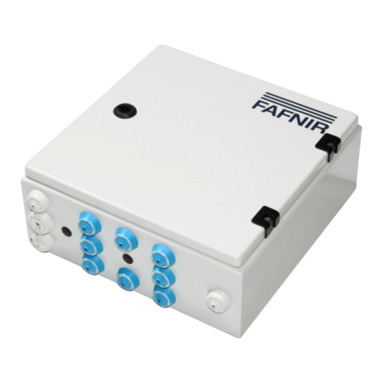
Page 8: Visy-Command
The wired (standard) version of VISY-Command has 2, 4, 8, or 16 sensor terminals. At each sensor terminal, it is possible to connect up to three different types of FAFNIR sensors VISY-Stick/Reed (e.g. one VISY-Stick, one VISY-Stick Interstitial and one VISY-Reed Sump). -
Page 9: Visy-Command Rf - Wireless Version (Radio System)
3.1.2 VISY-Command RF – wireless version (radio system) With the wireless version (RF), each VISY-Stick/Reed sensor is connected to one VISY-RFT transmitter, which transmits the measured data to VISY-Command RF. Up to 16 VISY-Stick/Reed sensors can be operated in conjunction with the VISY-Command RF. Each sensor is electrically powered via a battery in the VISY-RFT transmitter. -
Page 10: Installation
Installation When installing and operating the VISY-Command central unit, the requirements of the Explosion Protection Regulations, the Industrial Health and Safety Regula- tions and the Equipment Safety Regulations as well as generally accepted rules of engineering and these operating instructions must be observed. Observe also the local safety and accident prevention regulations, which are not stated in these operating instructions. - Page 11 V P b o a r d VP Platine t o V I - 4 i n t e r f a c e zum Interface VI-4 Sensor terminal block Sensor Sensor Sensor Sensor Messwertgebe r Messwertgebe r Messwertgebe r Messwertgebe r brown white...
-
Page 12: Visy-Command Rf - Wireless Version (Radio System)
The DIP switch S1 is used for the relevant settings: DIP switch S1: Service Function Configuration of VISY-Command using the VISY-Setup software application VISY-Quick protocol (FAFNIR protocol) Auxiliary measurement system No function Table 1: DIP switch S1 settings The RxD service LED (green) displays incoming data of the service interface. -
Page 13: Host Interface
4.3.1 Host interface The serial host interface (galvanically isolated) for communication with a higher-level system, e.g. POS, is designed to function as an RS-232 interface or an RS-485 interface. Depending on requirements, the host computer can be connected to the RS-232 interface or the RS-485 interface. -
Page 14: Extension Interface (Rs-485)
4.3.2 Extension interface (RS-485) The extension interface is a galvanically isolated RS-485 serial port through which data can be transmitted to other system components (e.g. VISY-View Touch if the host interface is busy). This interface is unidirectional. This means that data is only sent from VISY-Command to the system components connected there. -
Page 15: Dip Switch S2 For Bias (Rs-485 Host/Extension)
4.3.3 DIP switch S2 for bias (RS-485 host/extension) With the DIP switch S2, the RS-485 host interface (2.1./2.2) and the RS-485 extension interface (2.3/2.4) can be biased when required, in order to achieve a significant improvement of communication security. DIP switch S2: RS-485 bias Function Bias off (factory setting) Host bias... -
Page 16: Status Display
Status display After switching on or resetting the VI… interface, the firmware checksum is initially checked. If an error in the firmware is detected, the display shows permanently SE (Signature Error). Otherwise, the firmware version of the interface is displayed. This is shown in form of three numbers displayed in sequence, e. - Page 17 Code Message (VISY-Setup) Possible cause Required action Description Probe running No measures required. Probe not running If this status is displayed permanently, it must be assumed that the sensor is The measured values are no longer being defective.
- Page 18 Code Message (VISY-Setup) Possible cause Required action Description Checksum error: In case of wired operation, the cable Probe - Control Unit connection (also connectors and termi- nals) to the sensor is loose, dirty, or The central unit displays an error message damaged, or there is severe interfer- when communicating with the sensor or ence.
- Page 19 Code Message (VISY-Setup) Possible cause Required action Description Relevant to wireless mode only: Data from the sensors is only being Waiting for first wireless transmission transmitted periodically. Not required because of normal After switching on or resetting, the VISY- reset/switch-on behaviour.
-
Page 20: Reset Button
Before returning any FAFNIR equipment, the Return Material Authorization (RMA) from FAFNIR customer service is required. Please contact your account manager or the customer service to receive the instructions on how to return goods. The return of FAFNIR equipment is possible only with authorization by the FAFNIR customer care. Page 17/28... -
Page 21: Technical Data
Technical Data Details of the technical data can be found in the approvals and instructions. List of figures Figure 1: VISY-Command 8 with one VP-1 board for 8 sensors ..............8 Figure 2: VISY-Command 16 with two VP-1 boards for 16 sensors ............8 Figure 3: Interface VI-4 ............................... - Page 29 VP-2: 1 … 2 VP-4: 1 … 4 Communication (Cradle connector) 1 … 10 Table III.c: Terminal designation on the isolating amplifier Page 1/3 FAFNIR GmbH Schnackenburgallee 149 c 22525 Hamburg Tel.: +49 / (0)40 / 39 82 07-0 www.fafnir.de info@fafnir.de ...
- Page 30 III.f … maintenance (servicing and emergency repair) The isolating amplifier is generally maintenance-free. In case of a defect, it must be send back to FAFNIR or one of its representations. There is consistency with the requirements for the dielectric strength (according to EN 60079-11, clause 6.3.13) between the intrinsically safe sensor circuits and the auxiliary energy as well as the communication...
- Page 31 The isolating amplifier must be installed in a housing which has a degree of protection according to EN 60529 of at least IP20. Page 3/3 FAFNIR GmbH Schnackenburgallee 149 c 22525 Hamburg Tel.: +49 / (0)40 / 39 82 07-0 www.fafnir.de...
- Page 32 FAFNIR GmbH Schnackenburgallee 149 c 22525 Hamburg, Germany Tel.: +49 / 40 / 39 82 07-0 Fax: +49 / 40 / 390 63 39 E-mail: info@fafnir.com Web: www.fafnir.com...
Need help?
Do you have a question about the VISY-Command (VI-4) and is the answer not in the manual?
Questions and answers