Table of Contents
Advertisement
Quick Links
Advertisement
Table of Contents

Summary of Contents for Impulse Dymanics OPTIMIZER Smart System
- Page 1 ® OPTIMIZER Smart System Physician’s Manual For 2-Lead OPTIMIZER Smart System Study (FIX-HF-5C2) Limited by United States (Federal) law to investigational use Federal law restricts this device to sale by or on the order of a physician Part No.: 12-240-003-01-US Rev. 0...
- Page 2 Impulse Dynamics (USA), Inc 30 Ramland Road South, Suite 204 Orangeburg, NY 10962-2698 U.S.A. ® OPTIMIZER is a US registered trademark of Impulse Dynamics. OMNI™ is a trademark of Impulse Dynamics. CCM™ is a trademark of Impulse Dynamics. The information provided in this document may change without prior notice. This document and its contents are proprietary to Impulse Dynamics.
-
Page 3: Table Of Contents
TABLE OF CONTENTS EXPLANATION OF SYMBOLS ON LABELS ....................... I THE OPTIMIZER SMART SYSTEM: AN OVERVIEW ................1 Description of the OPTIMIZER Smart IPG ....................1 OPTIMIZER Smart IPG Lead Connectors ....................2 OPTIMIZER Smart IPG Physical Characteristics ..................2 OPTIMIZER Smart IPG Battery ....................... - Page 4 5.11 Home Appliances .............................14 5.12 Store Anti-Theft Systems/Airport Security Screening Systems ..............15 5.13 Industrial Machinery ..........................15 5.14 Transmitting Devices ..........................15 5.15 Cellular and Mobile Phones ........................15 POTENTIAL ADVERSE EFFECTS ......................16 DEVICE IMPLANTATION ........................... 16 General Considerations ..........................16 Opening the Lead Sterile Package(s) .......................17 Opening the OPTIMIZER Smart Sterile Package ...................17 Verifying Lead Placement ........................18 Connecting the Implanted Leads to the OPTIMIZER Smart IPG ............18...
- Page 5 10.1 Description .............................. 28 10.2 Programmer Functions ..........................29 10.3 Programmer Components ........................29 10.4 Interconnecting the Programmer Components for Operation ..............30 10.5 Programmer Wand........................... 30 10.6 Charging the Battery of the OMNI II Programmer Tablet PC ..............31 10.7 Operating the OMNI Smart Programmer ....................
- Page 6 12.10.2 Parameters ..........................50 12.10.3 Statistics ..........................52 12.10.4 Log Files ..........................53 12.10.5 Remote ...........................54 12.11 Status Bar ..............................54 INTERROGATION ............................54 13.1 Communicating with the Implanted OPTIMIZER Smart IPG..............54 13.2 Interrogating the OPTIMIZER Smart IPG....................55 MODIFYING PARAMETER VALUES ......................55 14.1 Parameter Color Convention ........................56 14.2 Parameter Conflicts ..........................56 PROGRAMMING ............................
- Page 7 23.3 Sensed Events ............................66 23.4 CCM Train Delivery..........................67 23.5 CCM Inhibit Conditions in Active OVO-LS-CCM Mode ..............67 23.6 CCM Signal Delivery State ........................67 23.7 Log Browser Window ..........................67 CCM SCHEDULE ............................68 ACTIVE OVO-LS-CCM MODE ........................69 25.1 Deactivated Parameters in Active OVO-LS-CCM Mode ................
- Page 8 31.6 Ending an OMNI Smart Programmer Remote Session ................89 31.7 Sending a Chat Message Using the OMNI Smart Programmer ...............89 31.8 OMNI II Log Upload/Download ......................89 31.8.1 OMNI II Upload/Download Log Window ...................89 31.8.2 OMNI II Refresh Local ........................90 31.8.3 OMNI II Refresh Server .......................90 31.8.4 OMNI II Log Files Upload ......................91 31.8.5 OMNI II Log Files Download ......................91 BLUETOOTH PRINTER ..........................
- Page 9 APPENDIX I ................................103 Physical Characteristics ........................... 103 Battery ................................103 Current Consumption ............................104 Safe Mode................................ 104 Programmable Parameters ..........................104 Factory Settings ............................... 106 Emergency Programming ..........................108 APPENDIX II ................................110 Electromagnetic interference information (Table 1 of 6): ................110 Electromagnetic interference information (Table 2 of 6): ................
- Page 10 THIS PAGE INTENTIONALLY LEFT BLANK viii...
-
Page 11: Explanation Of Symbols On Labels
EXPLANATION OF SYMBOLS ON LABELS SYMBOL DESCRIPTION Manufacturer Date of Manufacture Consult instructions for use. Caution, consult accompanying documents Transport Temperature Limits Sterilized with Ethylene Oxide Use By Do Not Reuse Part Number Lot Number Serial Number Open Here Torque Wrench Port Plug Do Not Use if Package is Damaged... - Page 12 SYMBOL DESCRIPTION Defibrillation-Proof Type BF Applied Part Produces Non-ionizing Electromagnetic Radiation Wand Power Indicator Emergency Programming Programming Interrogation Wand Signal Strength Indicator DC Power Input (charger connection) Serial data I/O port (for use only by Impulse Dynamics technical personnel) IPG-Charger Coupling Signal Strength Indicator ”Call Doctor”...
- Page 13 SYMBOL DESCRIPTION Battery Status Indicator OPTIMIZER Mini Charger OPTIMIZER Smart IPG...
- Page 14 THIS PAGE INTENTIONALLY LEFT BLANK...
-
Page 15: The Optimizer Smart System: An Overview
THE OPTIMIZER SMART SYSTEM: AN OVERVIEW The OPTIMIZER Smart system is intended for the treatment of moderate to severe heart failure. The system comprises the following components: • Programmable OPTIMIZER Smart Implantable Pulse Generator (IPG), Model CCM X10; port plug, #2 torque wrench for securing the implanted leads ™... -
Page 16: Optimizer Smart Ipg Lead Connectors
The implanting physician can select any standard ventricular pacing leads with the following characteristics: • Bipolar lead approved for transvenous intracardiac ventricular pacing. • Standard IS-1 bipolar connector. • Active fixation with electrically-active corkscrew distal electrode with a minimal electrically-active surface area of 3.6 mm •... -
Page 17: Optimizer Smart Ipg Battery
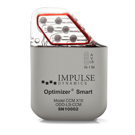
Figure 1: OPTIMIZER Smart IPG Figure 2: OPTIMIZER Smart IPG (front view) (back view) OPTIMIZER Smart IPG Battery The OPTIMIZER Smart IPG is powered by a Model QL0200I-A lithium-ion battery (Li- Ion) manufactured by Quallion and has a usable capacity of 0.2 Ah. The current consumption of the OPTIMIZER Smart IPG is highly dependent on the energy of the CCM signals delivered to the patient. -
Page 18: Extrapolated Battery Life
Extrapolated Battery Life The expected life of the Optimizer Smart IPG is limited by the expected service life of its rechargeable battery. The rechargeable battery inside the Optimizer Smart IPG should provide at least six years of service. Over time and with repeated charging, the battery in the Optimizer Smart IPG will lose its ability to recover its full capacity. -
Page 19: User Profile And Training
User Profile and Training The operators of the OPTIMIZER Smart System include patients, physicians (and trained medical personnel who assist them) and Impulse Dynamics Representatives. Physicians, medical personnel and Company representatives shall be familiar with operation of electronic medical equipment, particularly IPGs, and programmers. -
Page 20: Scientific Background About Heart Failure And Ccm
Patient training will be limited to the use of the OPTIMIZER Mini Charger and will be provided by Impulse Dynamics Representatives post implant. Scientific Background About Heart Failure and CCM Heart failure is a condition wherein the heart muscle does not pump blood as well as it should, generally resulting in reduced cardiac output, possibly due to reduced contraction force or impaired relaxation or other deficiencies. -
Page 21: Indications
The safety and performance of the OPTIMIZER Smart System is based on clinical investigations conducted with the prior generation device, the OPTIMIZER IVs and III Systems given the similarities between the Systems with regard to function, intended use, design characteristics, and the CCM signals. -
Page 22: Contraindications And Precautions
The OPTIMIZER Smart system delivers non-excitatory CCM signals to the heart and has no pacemaker or ICD functions. CONTRAINDICATIONS AND PRECAUTIONS Use of the OPTIMIZER Smart system is contraindicated in: 1. Patients with a mechanical tricuspid valve 2. Patients in whom vascular access for implantation of the leads cannot be obtained... -
Page 23: Ventricular Arrhythmias Potentially Caused By Ccm Signals
fixation and by limiting the number of lead manipulations. Please read and follow all directions of the original Physician Manual for the leads that you intend to use to minimize adverse events connected to lead implantation. 4.2.2 Ventricular Arrhythmias Potentially Caused by CCM Signals CCM signals are of greater strength than that of typical pacing pulses and are thus capable of eliciting activation of cardiac tissue when delivered outside of the absolute refractory period. -
Page 24: Handling
TYVEK/PET blister pack containing an inner TYVEK/PET blister. The following items are included in the shelf box: • OPTIMIZER Smart System Physician’s Manual • OPTIMIZER Smart System Patient’s Manual • Peel-off labels for use with implantation documents •... -
Page 25: Resterilization And Reuse
Resterilization and Reuse Do not resterilize the OPTIMIZER Smart IPG, Port Plug, or the Allen wrench provided with the device. An OPTIMIZER Smart IPG that has been explanted for any reason may not be reimplanted in another patient. Cremation The OPTIMIZER Smart IPG contains a sealed chemical battery and therefore must not be incinerated. -
Page 26: Rf Ablation
is used, only brief signal bursts may be delivered and the neutral electrode has to be positioned such that the current affecting the OPTIMIZER Smart IPG and the attached leads is minimized. The risk of adverse effects can be decreased by reprogramming the OPTIMIZER Smart IPG into Standby (OOO) mode. -
Page 27: Radiation Therapy
No particular paddle placement can avoid such damage. To decrease the risk, it is recommended to position the paddles as far away from the OPTIMIZER Smart IPG as possible. In addition, paddle positions that would bring the OPTIMIZER Smart IPG into the direct path of the defibrillation current should be avoided. -
Page 28: Lithotripsy
Lithotripsy Warning: Direct exposure of the OPTIMIZER Smart IPG to shock waves can damage the device. A device implanted outside the shock wave path presents no clear- cut contraindication to lithotripsy. Precautionary programming of the OPTIMIZER Smart IPG to Standby (OOO) mode reduces the risk of adverse effects. -
Page 29: Store Anti-Theft Systems/Airport Security Screening Systems
5.12 Store Anti-Theft Systems/Airport Security Screening Systems Certain types of anti-theft systems, such as those installed at entrances/exits of stores, libraries and other facilities, as well as airport security systems can interfere with the OPTIMIZER Smart IPG. Such interference would most often inhibit CCM signal delivery. -
Page 30: Potential Adverse Effects
POTENTIAL ADVERSE EFFECTS Examples of adverse effects that may occur as the result of the surgical procedure are listed below in the order of their clinical severity: 1. Death 2. Arrhythmias (brady- or tachyarrhythmias including fibrillation) 3. Stroke or TIA (“transient ischemic attack”) 4. -
Page 31: Opening The Lead Sterile Package(S)
Warning: During implantation, leads and catheters need to be manipulated with extra caution in order to avoid perforation of the right ventricular wall. Obtain X- rays, perform echocardiography, and device interrogation after implantation to detect perforations even in the absence of corresponding symptoms. Warning: In order to prevent vascular injury and hemorrhage, be extremely cautious when introducing catheters and leads into arteries and veins. -
Page 32: Verifying Lead Placement
Verifying Lead Placement Note: The Programmer Wand of the OMNI Smart Programmer is not sterile and cannot be sterilized. The Programmer Wand needs to be placed in a sterile cover before it can be brought into the sterile field. Place the Programmer Wand over the IPG. Ask the person operating the Programmer (outside the sterile field) to measure the lead impedances and make sure they are adequate. -
Page 33: Dissection Of The Ipg Pocket
Note: Alternately, any commercially available bipolar IS-1 port plug may be used to plug the atrial port of the OPTIMIZER Smart IPG. Dissection of the IPG Pocket Blunt dissection directly on top of the fascia is the preferred method for creating the pocket, which should be just large enough to accommodate the IPG and any loops of excess lead. -
Page 34: Optimizer Smart Ipg: Functions And Programming Options
• Prior to inserting the IS-1-BI lead connectors, verify visually that none of the set screws protrudes into any of the IPG header cavities. Back off any set screw found protruding beyond the wall into the header cavity by turning it back in a counter-clockwise direction with the Allen wrench. -
Page 35: Ccm Off Status
CCM Off Status Under certain conditions, which are listed below, the OPTIMIZER Smart IPG is set to a special “Off” status: • Permanent Off: In this state, the OPTIMIZER Smart IPG does not deliver CCM signals, although it senses and classifies cardiac events. This status can only be changed by using the OMNI Smart Programmer software to reprogram the OPTIMIZER Smart IPG under supervision of a physician. -
Page 36: Refractory Period
• Polarity: To configure A and V sensing, the OPTIMIZER Smart IPG provides the following options: o Bipolar: The signal between lead “tip” (distal electrode) and “ring” (proximal electrode) of a bipolar lead is sensed. o Unipolar: The signal between lead tip (distal electrode) and the case of the OPTIMIZER Smart IPG is sensed. -
Page 37: Ccm Signal Parameters
9.5.2 CCM Signal Parameters The CCM signal is a pulse train comprising a programmable number of consecutive pulses, each with two phases of opposite polarity and programmable duration. Accordingly, the common practical configuration is given by programming CCM to be delivered for one hour every few hours, for example 1 hour ON followed by 3:48 hours OFF, repeatedly, to produce 5 hours of CCM therapy per day. -
Page 38: Parameter Interaction
9.5.4 Parameter Interaction In order to avoid false event detections, the CCM signal has to be delivered entirely within the right atrial and right ventricular refractory period. Prior to the end of these refractory periods, an 86 ms long noise window is activated to detect external interference. -
Page 39: Conditions Causing Inhibition In Active Ovo-Ls-Ccm Mode
9.6.2 Conditions Causing Inhibition in Active OVO-LS-CCM Mode The following cardiac activities or events are sensed and detected by the OPTIMIZER Smart IPG while it is in its Active state. These events are also entered into the statistical data set, and they pertain to transmitted marker events. When CCM train delivery is on, such events inhibit CCM signal delivery. -
Page 40: Ccm Triggering Based On Local-Sense Events
CCM Triggering Based on Local-Sense Events Delivery of CCM signal trains is synchronized with the intrinsic myocardial electrical activity in the vicinity of the Local Sense (LS) electrode. The LS channel is configured to sense parameters that characterize the activity of a small, local (near the electrode) part of the heart. -
Page 41: Local Sense Refractory Periods In Active Ovo-Ls-Ccm Mode
The leading edge of the first event detected within this window is used to trigger CCM signal delivery. When an event is detected, the Local Sense Alert Window is immediately closed. Any Local Sense events detected after the window closes are considered to lie outside the Alert Window and lead to the LS Out of Alert Status. -
Page 42: Omni Smart Programmer System
10. OMNI SMART PROGRAMMER SYSTEM 10.1 Description The OMNI Smart Programmer System allows the physician to interrogate and program the OPTIMIZER Smart IPG. The programmer software runs on a Lenovo Touch screen Laptop connected to a Programmer Interface box. Communication between the Programmer Interface and the OPTIMIZER Smart IPG is accomplished with a Programmer Wand placed directly over the implant site. -
Page 43: Programmer Functions
10.2 Programmer Functions The programmer can perform the following: • Read (interrogate) OPTIMIZER Smart IPG parameters as currently programmed • Modify OPTIMIZER Smart IPG parameters • Read ECG signals from patient and display for analysis • Retrieve statistics accumulated by the OPTIMIZER Smart IPG as it operates •... -
Page 44: Interconnecting The Programmer Components For Operation
10.4 Interconnecting the Programmer Components for Operation • Plug the USB end of the Interface Box Cable into the USB port on the side of the ® Tablet PC. Plug the other end (fitted with a LEMO -type connector) into the port labeled USB on the back panel of the Programmer Interface Box. -
Page 45: Charging The Battery Of The Omni Ii Programmer Tablet Pc
Figure 5: OMNI II Programmer Wand 10.6 Charging the Battery of the OMNI II Programmer Tablet PC Warning: Only charge the OMNI II Programmer Tablet PC battery with the medical- grade power supply provided with the OMNI Smart Programmer system. Do not attempt to recharge the Tablet PC’s battery with any other power supply. -
Page 46: Using The Omni Ii Programmer Tablet Pc Touch Screen
10.8 Using the OMNI II Programmer Tablet PC Touch Screen The OMNI II Programmer Tablet PC is equipped with a touch screen. Selections on the screen may be made by touching the screen with one’s finger or the attached stylus. Caution: Using sharp items or regular writing equipment (pen, pencil) may damage the touch screen. -
Page 47: Routine Cleaning
10.11 Routine Cleaning Warning: DO NOT attempt to sterilize an OMNI Smart Programmer or the Programmer Wand because any such attempt could severely damage the equipment. Warning: DO NOT submerge any part of the OMNI Smart Programmer in water. Damage to the unit may result. The OMNI Smart Programmer System is not protected against ingress of water or humidity (ingress protection rating IPX0). -
Page 48: Omni Smart Programmer System Software
11. OMNI SMART PROGRAMMER SYSTEM SOFTWARE The OMNI Smart Programmer System software contains applications that are used to read and modify the parameters that control the OPTIMIZER Smart IPG. 11.1 Selection Screen When the OMNI Smart Programmer is turned on, a selection screen is presented upon completion of the start-up sequence. -
Page 49: Omni Ii
11.1.2 OMNI II The buttons contained within the OMNI II box are for use with the OPTIMIZER IVs IPG. For details please see OPTIMIZER IVs Physician’s Manual. • Clinical Mode: For regular programming of the OPTIMIZER IVs IPG • Remote Mode: For remote control of another OMNI Smart Programmer using the OMNI II Programmer software. -
Page 50: Basic Operation Of The Omni Smart Programmer Application
• Log File Manager: This selection allows special settings of OMNI Smart Programmer. It is to be used by Impulse Dynamics technical staff only and is not needed for regular clinical use. • Shutdown: Selecting the red Shutdown button on the Selection screen turns OFF the OMNI Smart Programmer. -
Page 51: Monitoring Tools
The Open and Save commands of the OMNI Smart Programmer software read and write data from and to standard (.tip) files. As such, the OMNI Smart Programmer software can also be used as an editor of standards (see Section 16). 11.2.3 Monitoring Tools The OMNI Smart Programmer System offers a Programmer Interface with a built-in electrocardiography channel. -
Page 52: The Omni Smart Programmer Screen
12. THE OMNI SMART PROGRAMMER SCREEN When the OMNI Smart Programmer software is started, it displays the main screen, which includes the following: • Title Bar • ECG Window • View Bar • ECG Statistics Bar • Tool Bar • Device Bar •... -
Page 53: Title Bar
12.1 Title Bar The Title Bar is displayed at the top of the window. It identifies the software currently running, and the source of the data, which can be either: • A OPTIMIZER Smart IPG, in which case the serial number of the device, and the date and time of the last interrogation are shown, or •... -
Page 54: Marker View
12.3.1 Marker View In Marker view, the Marker events are displayed as follows: • Sensed events, below the baseline, are represented by colored line markers which use the following color conventions: o Magenta: Atrial sensed event o Green: Ventricular sensed event o Black: Local Sense event These color references are displayed in the ECG window of the OMNI Smart Programmer Software screen. -
Page 55: Graph View
12.3.2 Graph View A graphical view is available on the OMNI Smart Programmer software to display some of the OPTIMIZER Smart IPG parameters in an easy-to-understand graph. This window displays the following parameter values: • Right Heart Sensing o Atrial Sensitivity o Ventricular Sensitivity o Atrial Refractory Period (PVARP) o Ventricular Refractory Period... - Page 56 The conventions for this graph are: • Atrial, Ventricular and LS events are displayed as vertical lines under the horizontal axis of the graph. • Sensing thresholds are displayed as small rectangles below the sensed events. The distance to the axis is proportional to their values. •...
-
Page 57: Ls Wizard
Left-clicking the keyboard mouse button or touching the screen with the stylus causes the graph to zoom in. Right-clicking the keyboard mouse button or touching the screen with the stylus’ button depressed causes the graph to zoom out. A scrollbar appears in the bottom of the graph when it is zoomed in. -
Page 58: Main Tool Bar
12.5 Main Tool Bar The Main Tool Bar is displayed under the ECG Window. It contains the buttons of the following OMNI Smart Programmer commands (Whenever a shortcut alternative exists for a command, it is denoted next to the command name in parentheses): •... -
Page 59: Device Bar
• Print Preview: Opens up the Print Preview window containing following buttons that can be selected for previewing their associated print functions: o Print Parameters: The list of the current OMNI Smart Programmer values to be printed is previewed. o Print Statistics: The list of the current statistics to be printed is previewed. o Print Follow Up: The list of the current Follow Up measurements to be printed is previewed. -
Page 60: Log Bar
12.7 Log Bar A special file in the OMNI Smart Programmer Software contains a record (log) of all the interactions between the OPTIMIZER Smart IPG and the OMNI Smart Programmer, including the date and time when these interactions occurred. Figure 17: Log Bar More information regarding an event in the log may be obtained by double-clicking on the event in the Log Bar. -
Page 61: Parameter Conflict Bar
12.9 Parameter Conflict Bar In the bar under the Programming Bar, parameter conflict messages are displayed. These messages indicate which parameter values are in conflict, why the parameters are in conflict and the name of the parameter tab in which the conflicting parameters appear. By clicking on an error message, a list of the parameters that are in conflict appears. -
Page 62: Follow Up
12.10.1 Follow Up The Follow Up bar contains the following tabs, each with their own panel: • Current Status: displays the current IPG status. • Sensing: contains the atrium, ventricle, and LS sensing threshold buttons which allows the user to measure the atrium and ventricle sensing thresholds. - Page 63 Figure 23: AV Setup Tab Figure 24: LS Setup Tab Figure 25: Impedance Tab Figure 26: Crosstalk Test Tab...
-
Page 64: Parameters
12.10.2 Parameters The Parameters Bar contains the following tabs, each with their own panel: • Overview: contains the most important parameters found under the A/V, LS, and CCM Train & Schedule tabs. • A/V: displays the operating mode, as well as the atrial and ventricular heart sensing and timing parameters. - Page 65 Figure 29: LS Tab Figure 30: CCM Train & Schedule Figure 31: Alarms Tab Figure 32: Settings Tab Parameter values are displayed in two different ways:...
-
Page 66: Statistics
• For enabling/disabling parameters (such as CCM Channels), checkboxes are used, and a symbol indicates that the option is selected. To change the option, select the box to the left of the parameter name. • For parameters that have a set of possible values, the parameter value is displayed in a box. -
Page 67: Log Files
of CCM delivered during the last scheduled CCM delivery session, and the number of battery discharge episodes. The panel of each tab can be viewed in Numeric Mode or Graph Mode Figure 33: Statistics On - General Tab (Numeric View) Figure 34: Statistics On - General Tab (Graph View) 12.10.4 Log Files... -
Page 68: Remote
Figure 35: Tool Bar with Log File Commands 12.10.5 Remote When the Remote button is selected, the programming commands on the Main Log Bar are changed to the following Remote commands: • Connect: opens the OMNI II Programmer Client window which allows the user to initiate a remote session. -
Page 69: Interrogating The Optimizer Smart Ipg
13.2 Interrogating the OPTIMIZER Smart IPG To read the parameter values of the OPTIMIZER Smart IPG: • Place (or replace, if necessary) the Programmer Wand over the OPTIMIZER Smart IPG implant site. • Perform one of the following actions: o Press the Interrogate button on the Programmer Wand, or o Select the Interrogate button on the Tool Bar, or o Select the Interrogate button on the Programming Bar, or o Press the keyboard shortcut <Ctrl+I>... -
Page 70: Parameter Color Convention
14.1 Parameter Color Convention The following color convention is used to represent the programmer’s parameter values and conflicts: • Black: for the current parameter values of the OPTIMIZER Smart IPG; i.e. the last interrogated/programmed parameter values. • Blue: for modified allowed values; i.e. parameter values that are different from the programmed values which if selected, will not result in a parameter conflict. -
Page 71: Programming
15. PROGRAMMING 15.1 Programming the OPTIMIZER Smart IPG Programming the OPTIMIZER Smart IPG with the modified parameter values is allowed only if no parameter conflict occurs. The Program button will indicate whether a modified parameter value is allowed in the following manner: •... -
Page 72: Cancel
15.2.1 Cancel If any parameter values have been modified but not yet programmed into the OPTIMIZER Smart IPG, the Cancel command will reset the parameter values to the last interrogated/programmed set. To cancel modifications, perform one of the following actions: •... -
Page 73: Opening A Standard File
16.1 Opening a Standard File To open a standard (.tip) file, perform one of the following actions: • Select the Open button on the Tool Bar, or • Press the keyboard shortcut <Ctrl+O> • An Open window will pop up containing the names and locations of the standard files that can be loaded. -
Page 74: Log And Ecg Recording
In all cases, an Open window will first pop up where the name of the marker file associated with the device will need to be selected. Then, a Save window will appear which will allow the user to enter the name and, if desired, create a new folder for the file that is to be exported. -
Page 75: Emergency Programming
19. EMERGENCY PROGRAMMING In an emergency, the OMNI Smart Programmer can program the OPTIMIZER Smart IPG with a safe parameter set [Standby (OOO) mode, CCM OFF]. This Emergency Programming can be performed even if the Programmer is turned OFF (either the Tablet PC is OFF or is not functioning). -
Page 76: Emergency Programming When The Programmer Is On
19.2 Emergency Programming When the Programmer is ON The Urgent Programming command can be used to program the OPTIMIZER Smart IPG with a safe parameter set [Standby (OOO) mode, CCM OFF]. To program the OPTIMIZER Smart IPG with a safe parameter set: •... -
Page 77: Resetting The Optimizer Smart Ipg
21. RESETTING THE OPTIMIZER SMART IPG The OPTIMIZER Smart IPG has protective mechanisms that maintain the internal consistency of the system. These mechanisms detect when an internal discrepancy (for instance, clocks not oscillating at the expected frequency) occurs. If in the unlikely event a malfunction of this type occurs, the OPTIMIZER Smart IPG will place itself into a safe state referred to as “DOWN”... -
Page 78: Ccm Signal Delivery Options
The Operating Mode choices are: • Standby (OOO): The device is placed in safe mode with no CCM signal delivery. • Active ODO-LS-CCM: The device uses atrial, ventricular, and local sense events as triggers for CCM signal delivery. • Active OVO-LS-CCM: The device uses only ventricular and local sense events as triggers for CCM signal delivery. - Page 79 The CCM Mode choices are: • CCM OFF • Continuous: For testing purposes only. Warning: The OPTIMIZER Smart IPG MUST NEVER be left in Continuous mode. • Timed: CCM signals will be delivered as scheduled by the CCM Schedule tab. Selecting Continuous will cause a warning window to appear.
-
Page 80: Marker Events
23. MARKER EVENTS The OMNI Smart Programmer can be used to set the OPTIMIZER Smart IPG into Marker Mode. Markers are flags that represent the various states of the device and events detected during its operation. In this mode, all events detected and generated by the OPTIMIZER Smart IPG are displayed in the ECG window synchronized with the patient’s ECG signal. -
Page 81: Ccm Train Delivery
23.4 CCM Train Delivery CCM signal delivery is represented by a marker in the shape of a blue rectangle whose width is in proportion to the duration of the CCM signal. 23.5 CCM Inhibit Conditions in Active OVO-LS-CCM Mode Labels for the following events are displayed: •... -
Page 82: Ccm Schedule
For the OPTIMIZER Smart IPG the log browser window is composed of the following elements: • Time scale that can be modified with the available options or typing a scale value. • Idx button that opens up a Marker index log window containing log items that can be used for navigation purposes. -
Page 83: Active Ovo-Ls-Ccm Mode
Note: When the parameter Scheduled is set to a specific value, the OMNI Smart Programmer software automatically calculates and sets the exact times for the On Time and Off time parameters using the default parameters for the Start Time and End Time. For instance, if CCM therapy rate is set to 7 hours per day distributed over 24 hours, it sets the following standard scheduling parameters: •... -
Page 84: Parameter Modifications In Active Ovo-Ls-Ccm Mode
Figure 44: Overview Tab in Active OVO-LS-CCM Mode Figure 45: A/V Tab in Active OVO-LS-CCM Mode 25.2 Parameter Modifications in Active OVO-LS-CCM Mode Below is a list of parameters that are modified when the OPTIMIZER Smart IPG is set to Active OVO-LS-CCM: •... -
Page 85: Marker Events In Active Ovo-Ls-Ccm Mode
25.3 Marker Events in Active OVO-LS-CCM Mode With the OPTIMIZER Smart IPG is set to Active OVO-LS-CCM in Marker mode, atrial events are ignored. As such, atrial event markers are not displayed in the ECG Window. Figure 46: ECG Window in Marker Mode (Active OVO-LS-CCM Mode shown) 26. -
Page 86: Loading Statistics
26.1 Loading Statistics To obtain the Statistics from the OPTIMIZER Smart IPG: • Place (or replace, if necessary) the Programmer Wand over the OPTIMIZER Smart IPG implant site. • Select the Statistics button on the Task Bar. • Select the Read button at the bottom of the Statistics bar. If the loading is successful, the Programmer will display the message “Read Statistics OK”. -
Page 87: Statistics Buttons
• On – Inhibition o Causes AT: number of atrial tachycardia beats detected during scheduled CCM delivery PVC: number of PVCs detected during scheduled CCM delivery Long AV: number of times Long AV condition detected during scheduled CCM delivery ... -
Page 88: Resetting Device Counters
26.2 Resetting Device Counters In order to reset the OPTIMIZER Smart IPG Statistics counters to zero: • Place (or replace, if necessary) the Programmer Wand over the OPTIMIZER Smart IPG implant site. • Select the Statistics button on the Task Bar. •... -
Page 89: Setting The Clocks On The Optimizer Smart Ipg And Omni Smart Programmer
Warning: After performing the lead impedance measurement, the operator should perform an interrogation to verify that the programmed values are set as intended. 28. SETTING THE CLOCKS ON THE OPTIMIZER SMART IPG AND OMNI SMART PROGRAMMER The time of day is maintained by an internal clock within the OPTIMIZER Smart IPG and is used by the CCM Therapy Delivery Scheduling mechanism to turn the CCM Signal on and off in accordance with the programmed CCM Schedule parameters. -
Page 90: Setting The Optimizer Smart Ipg Real Time Clock
28.2 Setting the OPTIMIZER Smart IPG Real Time Clock You can set the OPTIMIZER Smart IPG real-time clock either manually or by using the computer’s clock. In both cases: • Place (or replace, if necessary) the Programmer Wand over the OPTIMIZER Smart IPG implant site. -
Page 91: Setting The Omni Smart Programmer Clock
28.3 Setting the OMNI Smart Programmer Clock To set the system time of the OMNI Smart Programmer: • Select the Parameters button on the Task Bar. • Select the Settings tab on the Parameters bar. • Select the Set system time… button on the Settings panel •... -
Page 92: Maximum Lead Displacement
• Select the Parameters button on the Task Bar. • Select the Alarms tab on the Parameters bar. • Find the Minimum Target % for CCM Delivery on the Alarms panel. • Activate this function by setting the check () symbol in the checkbox next to Enable. -
Page 93: Local Sense (Ls) Scan
30. LOCAL SENSE (LS) SCAN The OMNI Smart Programmer software has a LS Scan tool which can be used to select appropriate operating parameters for the LS channel. To open the LS Scan tool: • Select the Follow Up button on the Task Bar. •... - Page 94 By acquiring these samples for different LS Sensitivity values, the timing of the LS event relative to the right-ventricular event is clearly demonstrated. The LS Scan results should be interpreted as follows: • Blue bars in the histogram indicate that the LS signal was sensed more than the number of times indicated by the Events per Bar parameter.
-
Page 95: Remote Operation
Figure 51: LS Setup Screen after Selection of Propose LS Button 31. REMOTE OPERATION The OMNI Smart Programmer allows remotely monitoring and controlling of the device via the Internet. Once connected, the operation is identical to the normal (local) operation, except that some commands may be disabled depending on the operating mode. -
Page 96: Connecting The Omni Smart Programmer To A Wired Ethernet Network
31.1 Connecting the OMNI Smart Programmer to a Wired Ethernet Network Note: The connection of the OMNI II Programmer Tablet PC to a wired internet network must only be done through the medical-grade Ethernet isolator. If use of the Remote Operation Mode is desired, and connection to the Internet is via wired network, the OMNI Smart Programmer must be connected to a standard 10/100 Ethernet network via the unused RJ-45 Ethernet port on the medical-grade Ethernet isolator attached to the bottom of the OMNI II Programmer Tablet PC. - Page 97 Figure 53: Network Configuration Window The Network configuration window displays the following information: • Wireless networks: a list of the available supported wireless networks with the following information: o Network name. o Signal strength percentage. o Connection status (“Connected” will appear next to the signal strength percentage if the OMNI Smart Programmer is connected to that network).
-
Page 98: Omni Smart Wireless Network Configuration Commands
31.2.2 OMNI Smart Wireless Network Configuration Commands The OMNI Smart Network configuration window provides the following command buttons: • Connect: connect to the selected wireless network. A password dialog will appear in which you must enter the network key (ask the network administrator for the key). -
Page 99: Omni Smart Master/Slave Modes
• Remote Listener Mode: for remotely monitoring an OMNI Smart Programmer in a clinical setting o A particular case of Remote Mode in which the OMNI Smart Programmer is not able to control the device (just monitoring operations are allowed). To open the desired startup mode, select the appropriate button on the OMNI Smart Programmer Selection screen. -
Page 100: Omni Ii Programmer Client Window
When the OMNI Smart Programmer is in Master mode (Remote or Clinical), it has total control of the OPTIMIZER Smart IPG, whereas when the OMNI Smart Programmer is in Slave mode, the commands that interact with the OPTIMIZER Smart IPG have been disabled (interrogation, programming, initiate marker mode, reading statistics etc.) 31.4 OMNI II Programmer Client Window Note: In order to connect the OMNI Smart Programmer to the OMNI Remote Server, the... -
Page 101: Show Omni Ii Programmer Client Window
Note: To use the remote operation feature of the OMNI Smart Programmer, a user must receive a unique user name and password from Impulse Dynamics. An appropriate Client Name must also be registered with Impulse Dynamics. Once all of the above information has been entered, press Enter or click on the Connect button. - Page 102 To start a remote session: • Start the Clinical Programmer in Clinical Mode o Select the Remote button on the Task Bar. o Select the Connect button on the Tool Bar. o When the Omni II Client window appears, enter the User name, password, and Client name in the appropriate spaces and then select Connect.
-
Page 103: Ending An Omni Smart Programmer Remote Session
31.6 Ending an OMNI Smart Programmer Remote Session An OMNI Smart Programmer remote session can be terminated from either the Clinical or Remote Programmer. In order to terminate an OMNI Smart Programmer remote session: • Select the Connect button on the Tool Bar again after a session has been initiated. -
Page 104: Omni Ii Refresh Local
Figure 57: Omni II Programmer Log Upload/Download Window 31.8.2 OMNI II Refresh Local In order to display the local log files stored on the OMNI Smart Programmer, click the Refresh Local button. 31.8.3 OMNI II Refresh Server In order to display the log files stored on the server, the OMNI Smart Programmer must first be connected to Internet. -
Page 105: Omni Ii Log Files Upload
31.8.4 OMNI II Log Files Upload In order to send log files to the server you must be connected to Internet and provide same information as above. This operation shall be performed only when the OMNI Smart Programmer is operating in Clinical Mode. 31.8.5 OMNI II Log Files Download In order to receive log files from the server you must be connected to Internet and provide same information as above... -
Page 106: Set Bluetooth
32.3 Set Bluetooth The pairing of the Zebra Bluetooth printer provided with the OMNI Smart Programmer has already been done prior to shipment. However if a replacement Zebra Bluetooth printer must be paired with the OMNI Smart Programmer, perform the following steps: •... -
Page 107: Set Default Printer
32.4 Set Default Printer To set the default printer for the OMNI Smart Programmer: • At the Selector screen, click the Configuration button. The Configuration Dialog window will appear. • Click the Set Default Printer button. The Set Printer window will appear. Figure 59: Set Printer Window •... - Page 108 Figure 61: Log File Manager 2.0 Window • To Delete files: o Select the check box to the left of the file name of each file to be deleted. o Click the Delete button. o When the Warning window appears, click Yes to confirm the file deletion. o Click on the X to close the Log File Manager 2.0 window.
-
Page 109: Optimizer Mini Charger
34. OPTIMIZER MINI CHARGER 34.1 Description The OPTIMIZER Mini Charger is a charger powered by a rechargeable battery. The system includes a permanently attached charging wand. The OPTIMIZER Mini Charger is supplied with an AC Adapter (Cell Con Battery Charger; Input: 110–240VAC, 50- 60Hz, 0.3A;... -
Page 110: Charger Features
34.2 Charger Features The following explains the features of the OPTIMIZER Mini Charger. • IPG-Charger Coupling Signal Strength Indicator: Bar graph display depicting connection between the charger and the OPTIMIZER Smart IPG • “Call Doctor” Indicator: 7-segment LED display for numerical codes •... -
Page 111: Charger Operation
Note: The OPTIMIZER Mini Charger is subject to interference from other electrical devices operated in the vicinity. Portable and mobile radio frequency equipment is especially prone to impair the normal function of the charger. If OPTIMIZER Mini Charger is not operating as expected, such interference has to always be taken into account. -
Page 112: Frequency Of Charging Sessions
Note: Improper positioning or displacement of the charging wand is indicated by the corresponding a low signal strength on IPG-Charger Coupling Signal Strength Indicator on the charger and by an audible signal sounding approximately once per second. Note: The charger will automatically discontinue the charging process if the charging wand is not repositioned onto the OPTIMIZER Smart implant site. -
Page 113: Numerical Codes
34.6 Numerical Codes The OPTIMIZER Mini Charger was designed to provide the patient with certain data and warnings appropriate to the situation. If the charger detects a situation that requires action, a code digit will appear on the “Call Doctor” Indicator. The following table gives a description of each numerical code: Will Charging Numerical... -
Page 114: Numerical Code 5
34.6.6 Numerical Code 5 When Numerical Code 5 is displayed, it means that the temperature of the OPTIMIZER Smart IPG at the beginning of a charging session is greater than 102.2°F. This Numerical Code may also be displayed if the temperature of the OPTIMIZER Smart IPG during charging increases by more than 3°... -
Page 115: Maintenance
34.8 Maintenance The OPTIMIZER Mini Charger does not contain any user serviceable parts. If the OPTIMIZER Mini Charger is not operational, please contact your Impulse Dynamics representative to obtain a replacement charger. Warning: No modification of this equipment is allowed. The battery inside the OPTIMIZER Mini Charger is expected to have a service life of 5 years. -
Page 116: Mandatory Battery Charging
In the event of complete failure of an IPG within 72 hours after implantation, Impulse Dynamics shall replace the failed IPG with a new one. Under this warranty, Impulse Dynamics shall not be liable if tests and analyses reveal that the alleged defect or non-conformity of the IPG is not present or was caused by improper use, neglect, improper implantation, or follow-up, unauthorized repair attempts by the user, or due to accident, fire, lightning, or other hazards. -
Page 117: Physical Characteristics
APPENDIX I As a convenience to the user, the following overview provides a brief and succinct summary of the characteristics of the OPTIMIZER Smart IPG. Some of these data are also presented in the manual in text form. Physical Characteristics Model OPTIMIZER Smart IPG Height (mm) -
Page 118: Current Consumption
Current Consumption Mode Current Less than 40 µA ODO-LS - CCM OFF Less than 45 µA ODO-LS - CCM ON Less than 1200 µA Current consumption of the OPTIMIZER Smart IPG is strongly dependent on the energy delivered by the CCM pulse train. Safe Mode Mode Description... - Page 119 CCM TRAIN PARAMETERS Parameters Name Values CCM Mode CCM OFF No pulse train enabled Timed As defined by the parameter values programmed under the CCM Scheduling Tab. Continuous The pulse train is enabled for the entire day. Number of Pulses 1, 2, or 3 CCM Train Delay Between 3 ms and 140 ms in 1 ms increments...
-
Page 120: Factory Settings
Factory Settings PARAMETERS RELATED TO CONTROLLING RIGHT HEART SENSING Mode Atrial Sense Amplifier Sensitivity 1.3 mV Ventricular Sense Amplifier Sensitivity 2.0 mV Ventricular Sensing Polarity Bipolar Atrial Sensing Polarity Bipolar Ventricular Refractory Period 250 ms Post-Ventricular Atrial Refractory Period 250 ms CCM PULSE TRAIN ACTIVATION CCM Pulse train enable CCM PULSE TRAIN TIMING... - Page 121 LS CHANNEL PROGRAMMABLE PARAMETERS LS Sensitivity 2.0 mV LS Alert Window Start -10 ms LS Alert Window Width 30 ms LS Pre-Atrial LS Refractory Period 5 ms LS Post-Atrial LS Refractory Period 5 ms LS Pre-Ventricular LS Refractory Period 0 ms LS Post-Ventricular LS Refractory Period 0 ms LS Post-LS Refractory Period...
-
Page 122: Emergency Programming
Emergency Programming PARAMETERS RELATED TO CONTROLLING RIGHT HEART SENSING Mode Atrial Sense Amplifier Sensitivity 1.3 mV Ventricular Sense Amplifier Sensitivity 2.0 mV Ventricular Sensing Polarity Bipolar Atrial Sensing Polarity Bipolar Ventricular Refractory Period 250 ms Post-Ventricular Atrial Refractory Period 250 ms CCM PULSE TRAIN ACTIVATION CCM Pulse train enable CCM PULSE TRAIN TIMING... - Page 123 LS CHANNEL PROGRAMMABLE PARAMETERS LS Sensitivity 2.0 mV LS Alert Window Start -10 ms LS Alert Window Width 30 ms LS Pre-Atrial LS Refractory Period 5 ms LS Post-Atrial LS Refractory Period 5 ms LS Pre-Ventricular LS Refractory Period 0 ms LS Post-Ventricular LS Refractory Period 0 ms LS Post-LS Refractory Period...
-
Page 124: Electromagnetic Interference Information (Table 1 Of 6)
Electromagnetic interference information (Table 1 of 6): GUIDELINES AND MANUFACTURER’S DECLARATION – ELECTROMAGNETIC EMISSIONS The OPTIMIZER Smart System (the OMNI Smart Programmer and the OPTIMIZER Mini Charger) is intended for use in an electromagnetic environment as specified below. The customer or user of the OPTIMIZER Smart System has to ensure that it is used in such an environment. -
Page 125: Electromagnetic Interference Information (Table 2 Of 6)
Electromagnetic interference information (Table 2 of 6): GUIDELINES AND MANUFACTURER’S DECLARATION – ELECTROMAGNETIC IMMUNITY The OPTIMIZER Smart System (the OMNI Smart Programmer and the OPTIMIZER Mini Charger) is intended for use in an electromagnetic environment as specified below. The customer or user of the OPTIMIZER Smart System has to ensure that it is used in such an environment. -
Page 126: Electromagnetic Interference Information (Table 3 Of 6)
Electromagnetic interference information (Table 3 of 6): GUIDELINES AND MANUFACTURER’S DECLARATION – ELECTROMAGNETIC IMMUNITY OF THE OMNI Smart PROGRAMMER The OMNI Smart Programmer is intended for use in an electromagnetic environment as specified below. The customer or user of the OMNI Smart Programmer has to ensure that it is used in such an environment. Immunity test IEC 60601 test level Compliance level... -
Page 127: Electromagnetic Interference Information (Table 4 Of 6)
The OMNI Smart Programmer and the OPTIMIZER Mini Charger are intended for use in an electromagnetic environment as specified below. The customer or user of the OPTIMIZER Smart system has to ensure that the equipment is used in such an environment. -
Page 128: Electromagnetic Interference Information (Table 5 Of 6)
Electromagnetic interference information (Table 5 of 6): Recommended separation distances between portable and mobile RF communications equipment and the OMNI Smart Programmer or OPTIMIZER Mini Charger Both the OMNI Smart Programmer and the OPTIMIZER Mini Charger should be used in an electromagnetic environment with limited radiated RF noise. -
Page 129: Communications/Telemetry
APPENDIX III Communications/Telemetry Between the OPTIMIZER Smart IPG and the OMNI Smart Programmer: • OPTIMIZER Smart IPG to OMNI Smart Programmer: o PPM: “0” = 180 µs, “1” = 270 µs o 14.5 kHz LC excited by pulse o 1 cycle per pulse until dampened to 10% o Energy invested per pulse 0.36 µJ →...