Table of Contents
Advertisement
Advertisement
Table of Contents

Summary of Contents for SIFANG CSC-196
- Page 1 CSC-196 Time Synchronization Device for Power System Manual...
- Page 2 File No. : 0SF.459.057(E) Date of issuing: August 2010 All rights reserved: Beijing Sifang Automation Co., Ltd. Note: we keep the right to modification. In case of deviation between the product and the instruction, please contact us in time, we will provide relative services.
- Page 3 You are appreciated for use our product. For safe, correct and effective application of this device, please pay attention to the followings: 1) The instruction is only for CSC-196 (Time synchronization device for power system). 2) Please read the instruction carefully, and adjust, test and operate your device accordingly.
-
Page 4: Table Of Contents
Contents 1.General…………………………………………………………………1 1.1.Brief introduction of the device………………………………………………………………...1 1.2.Functions…………………………………………………………………………………….….1 2.Technical parameters…………………………………………………...3 2.1.Main technical parameters……………………………………………………………………...3 2.2.Environmental condition……………………………………………………………….……….6 2.3.Electrical insulation…………………………………………………………………….……….6 2.3.1.Dielectric strength ........................6 2.3.2.Insulation resistance ......................... 6 2.4.Mechanical properties…………………………………………………………………………..6 2.4.1.Vibration………………………………………………………………………………………6 2.4.2.Impact…………………………………………………………………………………………6 2.4.3.Bump………………………………………………………………………………………….7 2.5.Electromagnetic compatibility………………………………………………………………….7 2.5.1.Electrostatic discharge immunity ..................... 7 2.5.2.Radiated radio-frequency electromagnetic field immunity ............7 2.5.3.Electrical fast transient/burst immunity ................... - Page 5 6.3.Available information code for the device…………………………………………………….50 Appendix A Operating instruction of configuration serial port……….51 A.1 Connection of configuration serial port………………………………………………………51 A.2 Definition of configuration serial port wire…………………………………………………..52 A.3 CSC-196 device default configuration………………………………………………………..52 A.4 Serial port configuration order………………………………………………………………..53 A.5 Operating state definition and fault handling method………………………………………...67...
- Page 6 Appendix B Configuration parameters displayed on the front panel…70 Appendix C Configuration method of network time comparing card...71 Appendix D Serial port message output format………………………74 Appendix E IRIG-B Standard format…………………………………77 Appendix F Operating mode of the run-standby mode time synchronization system………………………………………………..80...
-
Page 7: General
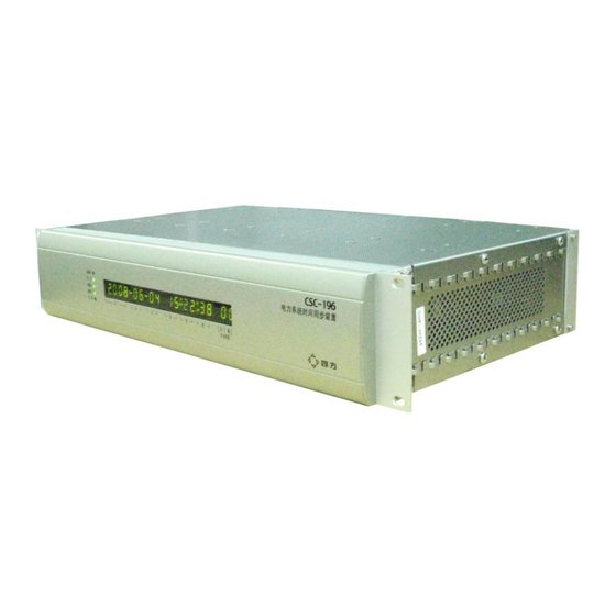
1. General 1.1. Brief introduction of the device The CSC-196 power system synchronous clock device (hereinafter as “the device” for short) is a timing reference signal output device that is developed and produced by Beijing Sifang Automation Co., Ltd. (hereinafter as “Sifang” for short) according to Specifications of time... - Page 8 CSC-196 Time synchronization device for power system Manual guarantee time accuracy of the output signal to be better than 1us, meet requirement of PMU and so on to accurate time-transfer signals. 4) Many time synchronization signals such as the time comparing pulse, IRIG-B, serial port time message and network time message (SNTP) can be able to output.
-
Page 9: Technical Parameters
Operating temperature range: - 40℃ to +70 ℃ 4) Clock configuration plan: CSC-196 may form all time synchronization systems such as the basic mode, master-slave mode and run-standby mode by using various signal receiving cards freely, refer to Section 4.2 of this instruction for details. - Page 10 CSC-196 Time synchronization device for power system Manual from close to open is for punctual edge; b) 820 nm multimode ST fiber interface: time accuracy is better than 1us. c) 1310 nm monomode SC fiber interface: time accuracy is better than 1us.
- Page 11 CSC-196 Time synchronization device for power system Manual Accuracy of time synchronization: better than 10ms. 9) Configuring method of output card: Various configuring method based on signal receiving card and power supply card (refer to Section 3.1), up to 6~8 time signal output cards per device are available, Max. output signal...
-
Page 12: Environmental Condition
CSC-196 Time synchronization device for power system Manual 2.2. Environmental condition The device can operate continuously and normally: Ambient temperature: operating ambient temperature is -10℃~+55℃. Temperature storage during transportation is -25℃~+70℃. No energizing quantity is applied under the limiting value, the device has no irreversible change, after temperature resumed, the device can operate normally. -
Page 13: Bump
CSC-196 Time synchronization device for power system Manual 4.2.2. 2.4.3. Bump The device can resist a Class 1 bump test specified in GB/T14573-1993, 4.3. 2.5. Electromagnetic compatibility 2.5.1. Electrostatic discharge immunity The device can resist a Class IV electrostatic discharge immunity test specified in GB/T 17626.2-1998. -
Page 14: Safety Performance
CSC-196 Time synchronization device for power system Manual 17626.12-1998. 2.6. Safety performance The device can comply with safety class I of GB 16836, not less than IP 20. 2.7. Alarm output contact capacity Operating capacity: if voltage is not more than 250V, allowable long term operating current is 3A,... -
Page 15: Cards Arrangement
CSC-196 Time synchronization device for power system Manual 3. Hardware description 3.1 Cards arrangement Hereinafter is the cards installation drawing (the rear view of the case), assembly of cards should comply with following basic principles: 1) The main signal receiving card is necessary, which must be assembled at position 1 (the leftmost slot);... -
Page 16: Main Signal Receiving Card (Code J)
CSC-196 Time synchronization device for power system Manual Fig. Panel of power supply card 1) There are 3 kinds of optional cards, D1 is a DC 110V card, D2 is a DC 220V card, D3 is a DC 125V card,. - Page 17 CSC-196 Time synchronization device for power system Manual optical fiber interface, Max. 2 channels of time reference signals can be connected to each card, the input signals have two kinds: IRIG-B(DC) time comparing code: the first channel of IRIG-B time comparing codes...
-
Page 18: Sub-Signal Receiving Card (Code Jf)
CSC-196 Time synchronization device for power system Manual jumpers are open motherboard to the P+ P- terminals output J4 jumps to BAK_PPS: transfer the first channel impulses signals on the sub-board to the P+ P- terminals output J5 jumps to GPS/B/F_RXD: transfer the second channel impulse signals on... -
Page 19: Serial Port Message Output Card (Code T)
CSC-196 Time synchronization device for power system Manual Jumper setting of the sub-signal signal receiving card JF: Card code Jumper name Jumper setting method J2, J3 Jump to the side of GPS/B/F J8, J9 Jump to the right side of the card... -
Page 20: Idle Contact Type Signal Output Card (Code K)
Manual Type, baud rate and output interval of the RPS and RPM message can be set through the configuration serial port, refer to Appendix A. Default setting is Sifang second message from RPS, and Sifang minute message from RPM. 3) Terminal definition: When the output interface is RS-232, the output terminal “+”... -
Page 21: Multimode Optical Fiber Output Card (Code F)
CSC-196 Time synchronization device for power system Manual PROG PULSE Output programmable pulse, set through the configuration serial port 3) Output characteristic: Corresponding relation between the static idle contact and TTL level signal is contact close to high level of TTL, contact open to low level of TTL, and jumping from open to close to punctual edge;... -
Page 22: Differential Signal Output Card (Code C)
CSC-196 Time synchronization device for power system Manual 2) The F1 card supports 4 channels optical output, and F2 for 2 channels (Output 3 and 4 are not available). 3) Jumper setting method: choose output 1, 2, 3 and 4 output signal types by jumper J1, J2, J3 and J4 on the unit. -
Page 23: Ttl Output Card (Code L)
CSC-196 Time synchronization device for power system Manual 1) The code of a differential signal output card is C1, painting C on the card baffle. 2) The card C1 outputs 8 channels of RS422/485 signals, choose 8 channels of outputs to be the chosen signals at the same time by the jumper J4. -
Page 24: Network Time Comparing Card (Code N)
CSC-196 Time synchronization device for power system Manual 3) IRIG-B FORMAT: comply with Specifications of time synchronization system for power system,be compatible with IEEE C37.118-2005 (refer to Appendix E for details)。 4) Time accuracy of second punctual edge: better than 1us. -
Page 25: Irig-B (Ac) Output Card (Code A)
CSC-196 Time synchronization device for power system Manual 3.11 IRIG-B (AC) output card (Code A) 失电 失电 IRIG-B(AC) IRIG-B(AC) Fig. 3-14 Panel of IRIG-B (AC) card A 1) There are two types of IRIG-B (AC) cards: A1 produces and outputs 3 channels of signals, if IRIG-B (AC) is required, only one card is available for each device;... -
Page 26: Monomode Optical Fiber Output Card (Code H)
Output RPM message(Only for V2 or more) programmable pulse output Output programmable pulse, setting by configuration of serial port(Only for V2 or more) 3.13 Front panel Refer to Fig. 3-14 for arrangement of the CSC-196 panel: CSC - 196 SYNC ×× ××... - Page 27 CSC-196 Time synchronization device for power system Manual Fig. 3-14 Panel arrangement of the device 1) PPS indicator: the pulse per second output indicator, after initialization of the device, and output time signals, keep once per second flashing. 2) SYNC indicator: for synchronization status of input and output signals.
- Page 28 CSC-196 Time synchronization device for power system Manual receiving card receiving BD, typically BD signal has higher priority than IRIG-B, so the Input I indicator, I Time Quality nixie tube correspond to the input state of sub-signal receiving card BD, while theInput II indicator, II Time Quality nixie tube correspond to the input state of main signal receiving card IRIG-B.
- Page 29 CSC-196 Time synchronization device for power system Manual More than a week of power off in the device, and switch Not obtaining leap on again. Usually GPS OEM board needs several minutes second information to get leap second from the satellite system, and then enters into normal operating state.
- Page 30 CSC-196 Time synchronization device for power system Manual within 5s after power on of the device, refer to Appendix B for details. Refer to Section 5.4 for the methods to judge operating status of the device by information displayed on the front panel.
-
Page 31: Engineering Application
CSC-196 Time synchronization device for power system Manual 4. Engineering application 4.1. About the typical time synchronization systems There are many forms of time synchronization systems, the typical forms include the basic, master-slave mode and run-standby mode, the section will give brief introduction for them, contents here refer to Specifications of time synchronization system for power system. -
Page 32: Run-Standby Mode Time Synchronization Time Transmission System
CSC-196 Time synchronization device for power system Manual Wireless signal Wired time reference signal Maser clock Other slave Slave clock Slave clock clocks • • • • Device Device Fig. 4-2 Structure of master-slave mode time synchronizatin system 4.1.3. Run-standby mode time synchronization time transmission... -
Page 33: Csc-196 Configuration Scheme
4.2. CSC-196 Configuration scheme 4.2.1. General description of the configuration scheme A CSC-196 device can form many time synchronization system freely by configuring various signal receiving cards, such as the basic, master-slave mode and run-standby mode. The section will introduce typical configuration schemes. -
Page 34: Master-Slave Mode Time Synchronization System(Single Channel Gps
IRIG-B time comparing code. Detailed input signal type (such as BD OEM board, GPS OEM board, IRG-B) and input signal polarity in input channel configuration information, CSC-196 can identify type and polarity of input signals automatically and make relative treatment. -
Page 35: Master-Slave Mode Time Synchronization System (Gps Standby Each Other)
CSC-196 Time synchronization device for power system Manual receiving receiving card configurat card card master-slave mode (basic) time synchronization J1/J6 1AN2NN system master clock(single channel GPS) master-slave mode time synchronization system slave J2/J7/J5/J 1BN2NN clock GPS Antenna Master Slave Config Serial... - Page 36 CSC-196 Time synchronization device for power system Manual GPS Antenna Master Slave Config Serial Config Serial Input1 Output 1 Output 3 Input2 Output 2 Output 4 Fiber Output Unit GPS Unit GPS Unit Fiber Input Unit Other slaves Fig. 4-5 Connection of master-slave mode time synchronization system (GPS standby each...
-
Page 37: Master-Slave Mode Time Synchronization System(Gps/Bd Standby Other Each
CSC-196 Time synchronization device for power system Manual 4.2.5. Master-slave mode time synchronization system ( GPS/BD standby other each) Only the signal card J/JF support this configuration scheme. Main Sub-signa Input Outp signal channel receiving receiving configurat card card card... -
Page 38: Run-Standby Mode Time Synchronization System (Gps Standby Each
CSC-196 Time synchronization device for power system Manual 4.2.6. Run-standby mode time synchronization system (GPS standby each) Solutions for forming run-standby mode time synchronization system (GPS standby each other )with signal receiving card J/JF: Main Sub-signa Input Outp signal channel... - Page 39 CSC-196 Time synchronization device for power system Manual Main Sub-signa Input Outp signal channel receiving receiving configurat card card card Run-standby mode time synchronization system master clock ( GPS standby each J1/J6 1AN2BN other ) Run-standby mode time synchronization J5/J8 1BN2BN system 的...
- Page 40 CSC-196 Time synchronization device for power system Manual Run-standby mode time synchronization system (GPS/BD 4.2.7. standby each other) The configuration scheme is only supported by the signal card J/JF: Main Sub-signa Input Outp signal channel receiving receiving configurat card card...
-
Page 41: Connecting To Time Synchronization Network
Fiber Input Unit Fiber Input Unit Other slaves Fig. 4-11 Connection (monomode) of run-standby mode time synchronization system(GPS/BD standby each other) 4.2.8. Connecting to time synchronization network CSC-196 can support to connect the time synchronization network, the signal interfaces are all for... -
Page 42: Connecting Method Of Client-Side Equipments
IRIG-B time comparing code output from this master clock will be marked as abnormal synchronization (the CSC-196 mark is 3, refer to special running state of the master clock), the second punctual edges of all output time signals can keep ± 1us precision yet, and synchronization state in the output serial port message is normal too. -
Page 43: Installation, Commissioning And Operating Maintenance At Site
CSC-196 Time synchronization device for power system Manual 5. Installation, commissioning operating maintenance at site 5.1. Requirement for antenna installation 5.1.1. GPS antenna installation requirement The GPS antenna should locate the top of a building or other open area, and the top of the antenna should keep horizontal. -
Page 44: Requirement For Bd Antenna Installation
There should be no obvious barrier within 50m southerly, the other installing requirements are same with the GPS antenna. 5.2. Routine initialization After field installation of the CSC-196, start initialization as following: Connect the GPS antenna, BD antenna, optical fiber, cable and so on with relative terminals of the device. -
Page 45: Initialization Of Bd Signal Receiving Card
For a BD time-transfer solution, there must be the GPS signal receiving cards in the same CSC-196 or another CSC-196 at the same place, so connect it with the GPS antenna and power on, wait for the CSC-196 to lock the satellite normally and start to output time comparing signals. -
Page 46: Operating Maintenance
CSC-196 Time synchronization device for power system Manual board checking order $q;; observe quantity of satellites locked by the BD OEM board, typically 3 satellites are available, or check location of the BD antenna. 5.4. Operating maintenance Observe the front panel to learn operating condition of the device, the device should finish... - Page 47 CSC-196 Time synchronization device for power system Manual Table 5-2 Front panel display in abnormity and remedy Display Symptom Remedy panel The device is in initialization, usually the reason is all input time signals are abnormal, check the indicators of all PPS indicator input channels and the time quality nixie tube.
- Page 48 IRIG-B output from the device made by others can reach 1us precision or not. The input signal is the IRIG-B output from the other CSC-196: Check connection of optical fiber and cable, check for hardware fault at the output and input interfaces.
- Page 49 CSC-196 Time synchronization device for power system Manual Unstable satellite GPS/BD OEM board serial port message showing Check location and connection of the antenna locking(2Dfix) unstable satellite locking(2Dfix) The faulty channel corresponds to the OEM board Abnormal input Existed possibility:...
- Page 50 CSC-196 Time synchronization device for power system Manual In positioning, normal state, but invalid PPS output that 3 BD satellites are locked. So location of the BD antenna must be guaranteed. Lack of satellite, wait for good receiving, invalid PPS...
-
Page 51: Ordering Information
CSC-196 Time synchronization device for power system Manual 6. Ordering information 6.1. Requirement for ordering Please give the following characteristic parameters clearly during ordering: 1) Network forming mode of the time synchronization system: basic type, master-slave mode, and run-standby mode; Connection mode and optical cable length between screens should be determined. -
Page 52: Configuration List Of Single Device
CSC-196 Time synchronization device for power system Manual 6.2. Configuration list of single device Card Name of part Functions Qty. Remark code DC 110V double power supply Power supply card required, configure two power DC 220V supply cards Receive satellite... - Page 53 CSC-196 Time synchronization device for power system Manual Receive multimode optical fiber signal, and transfer the signal to the main signal receiving card Receive BD satellite signal, and transfer the signal to the main signal receiving card Receive monomode optical fiber signal, and transfer the signal to...
- Page 54 CSC-196 Time synchronization device for power system Manual IRIG-B (DC) by jumper. V2 or more can support programmable pulse output and RPM message output. Network time Support 2 channels of SNTP network time comparing Physical isolation between comparing card Ethernet ports...
- Page 55 CSC-196 Time synchronization device for power system Manual available since April 2009 30m/50m/100m/150m Equal to configuration quantity of GPS antenna Standard antenna/with lightning protection G4, J1 and JF1 Equal to configuration quantity of BD antenna 30m/50m/100m...
-
Page 56: Available Information Code For The Device
CSC-196 Time synchronization device for power system Manual 6.3. Available information code for the device Available information code format for CSC-196 : CSC196_Jx_JFx_*K_*Tx_*Bx_*Fx_*N_*Ax_*Hx_*Cx_*Lx *Dx。 Where x refers to the type code of the card, and * refers to quantity of the card. -
Page 57: Appendix A Operating Instruction Of Configuration Serial Port
The configuration serial port can realize checking and setting of parameters and operating mode of the device. Connect the computer serial port and the CSC-196 configuration serial port with the special serial port wire, set the serial port parameters of the computer: 8 digits of data bit, 1 stop bit, no verification, baud rate 9600, ASCII code sending and display. -
Page 58: Definition Of Configuration Serial Port Wire
As the figure, 2, 3 and 4 of the USB terminal head are connected to 3, 2 and 5 of the DB-9 hole type terminal with flat cable. There is a configuration serial port wire in the packing list of each CSC-196, the user or engineering personnel should take care of the configuration serial port wire at site. -
Page 59: Serial Port Configuration Order
CSC-196 Time synchronization device for power system Manual (3) Time compensation values of all input and output channel are 0; (4) Odd is adopted for all input and output IRIG-B; (5) The PPM port outputs minute-pulse; (6) The RPM port outputs square format message, with baud rate 4800bit/s, minute-message output mode (output interval is 60s, at the moment of full minute);... - Page 60 CSC-196 Time synchronization device for power system Manual Since the general response message may appear in many configuration response messages, here introduce together. CFG CHK ERR↙——Configuration order check error. SAME CFG↙——The configuration parameters are same with existed configuration, no function.
- Page 61 CSC-196 Time synchronization device for power system Manual Checking message: Flow Messag Message Function direct Message content Example e head trailer ; ( English None nload semicolon) Call version number VER: x.xx↙ ( x.xx is the version number of the main signal...
- Page 62 CSC-196 Time synchronization device for power system Manual Input checking mode of IRIG-B: IN IRIG-B: checking mode↙ Output checking mode of IRIG-B: OUT IRIG-B: checking mode↙ PPM port output pulse type: PPM PORT OUTPUT pulse type↙ PPS, PPM, PPH are available for the PPM port output pulse type, default is PPM Altitude saved in FLASH(Only for the device with a BD module):...
- Page 63 CSC-196 Time synchronization device for power system Manual START TIME: x x x x x END TIME: x x x x x Non-configured summer time: SUMMER TIME NOT SET ; ( English None nload semicolon) Example 1: Hardware version information: $Re: HARDWARE VERSION: J--004.223↙: Main signal receiving...
- Page 64 CSC-196 Time synchronization device for power system Manual Refer to Appendix A.5 for detailed definition of WORK STAT, ERR INPUT1.1: STAT, WORNG STAT GPS M12 + TIME QUALITY: 0x0 Output time quality: WORK STAT: 0x07 OUTPUT TIME QUALITY: Output time quality↙...
- Page 65 CSC-196 Time synchronization device for power system Manual HEIGHT: 74.0 TRACKED SATELLITE: 03 IN1.1: print the IRIG-B original element from channel 1 of the main signal receiving board; IN1.2: print the IRIG-B original element from channel 2 of the Example 1: main signal receiving board;...
- Page 66 CSC-196 Time synchronization device for power system Manual Configuration message Flow Messag Message Function direct Message content Example e head trailer 1XX2XX Example: 1: Main signal receiving card; $i1AN2BN;: the master clock of the 2: Sub-signal receiving card; run-standby mode time synchronization...
- Page 67 CSC-196 Time synchronization device for power system Manual board channel 1 input; device is set to 500ns, viz. the second punctual edge of the output signal has 500ns IN2.2: Set the compensation value of the sub-signal receiving in advance. board channel 2 input;...
- Page 68 CSC-196 Time synchronization device for power system Manual FLASH WRITE OK $Re: RPS: BAUD=9600, TYPE=STD, INT=60s FLASH WRITE OK PPS——PPM port output PPS ; ( English PPM——PPM port output PPM $pPPH; nload semicolon) PPH——PPM port output PPH Set output pulse type Note: The configuration will be valid as soon as sending.
- Page 69 CSC-196 Time synchronization device for power system Manual Send specified altitude coordinate to the BD OEM board, and save it in the FLASH. Note: Only when receiving altitude information, can the BD OEM board computer position information; in case of the BD antenna position changing, a...
- Page 70 CSC-196 Time synchronization device for power system Manual cancel verification, the output IRIG-B signal cannot be set to None. Default parameters of the device: both input and output use odd. IRIG-B should use ODD according to Specifications of time synchronization system for power system (Appendix E), the other verification mode is only used during testing.
- Page 71 CSC-196 Time synchronization device for power system Manual minute since 8:0:2, February 1, 2009 $m09 02 01 08 03 03,1h; Refer to output PPH at 3m:3s per hour since 8:3:3, February 1, 2009 $m09 02 01 04 03 03,1d; Refer to output PPD at 4:3:3 per day since 4:3:3, February 1, 2009 $mCLR;...
- Page 72 CSC-196 Time synchronization device for power system Manual BOROADEN FIX LOGIC CLEAR OK——set to disable broaden satellite locking condition logic successfully 下行 ;(英文分号) 示例: S xx xx xx xx xx E xx xx xx xx xx I y; S xx xx xx xx xx Set summer time starting time: S month date $uS 03 21 00 00 00 E 10 23 00 00 00 I 1;—...
-
Page 73: Operating State Definition And Fault Handling Method
1us precision requirement or not, check optical fiber and cable connection, check hardware of the output and the input interface. 3. Input signal is IRIG-B from the other CSC-196: Check connection of optical fiber and cable, check hardware of the output and the input interface. - Page 74 CSC-196 Time synchronization device for power system Manual 1. When the device is resuming the track locking state from long term punctual keeping state, this fault may appear, it can resume automatically in short term. Except for this, abnormity, make follow-up check.
- Page 75 CSC-196 Time synchronization device for power system Manual IRIG-B output from the clock complies with Appendix E, and IRIG-B verification bit for odd, if the verification mode is different, modify verification mode of input IRIG-B of CSC-196 by $k. 2. Check hardware connection of input IRIG-B signal.
- Page 76 CSC-196 Time synchronization device for power system Manual Appendix Configuration parameters displayed on the front panel The front panel will display main configuration parameters within 5s after power on, if the configuration serial port cannot be connected, the operating parameters can be checked by this way, the...
- Page 77 CSC-196 Time synchronization device for power system Manual Appendix C Configuration method of SNTP card The network time comparing card can configure IP and subnet mask of network port 1 and 2. the Ethernet 1 default IP is 192.168.1.200, the subnet mask is 255.255.255.0, no gateway (0.0.0.0); the Ethernet 2 default IP is 192.168.2.200, the subnet mask is 255.255.255.0, no gateway (0.0.0.0).
- Page 78 CSC-196 Time synchronization device for power system Manual The ip2.cfg: Chang the IP1 or IP2 by what you want. Save and upload to the ftp server, then reset the device. Resume default IP: Use ethernet message send software tools, send the specified UDP message to resume default ip.
- Page 79 CSC-196 Time synchronization device for power system Manual 3. Select Send -> Select Send Adapter. 4. Select Send -> Transmit One. 5. Reset device.
- Page 80 CSC-196 Time synchronization device for power system Manual Appendix D Serial port message output format Square format: Serial port parameter: Default baud rate is 4800bit/s. There are 8 data bits, and 1 stop bit, no odd and even verification. Message format: “00,FF,81,day,month,year,hour,minute,second,synchronization state”...
- Page 81 CSC-196 Time synchronization device for power system Manual Corresponding ASCII value of the hexadecimal number composed by the following 4 bits: Bits 03-00: time quality: 0x0: Normal operating condition, the clock synchronization normally 0x1: the clock synchronization is normal, time accuracy is...
- Page 82 Manual End sign The CSC-196 totally support RPM, RPS two channels of serial port message output, and the RPM and RPS output message format, baud rate, and output time interval can be configured. Refer to Appendix A. Default output of the RPM port is the square format message, with baud rate 4800bit/s and minute message output mode (output interval is 60s, full minute output).
-
Page 83: Appendix E Irig-B Standard Format
CSC-196 Time synchronization device for power system Manual Appendix E IRIG-B Standard format Refer to Table E.1 for element definition of IRIG-B element, and refer to Fig. E.1 for wave form. Time in IRIG-B is Beijing Time. Table E.1 IRIG-B element definition Element No. - Page 84 CSC-196 Time synchronization device for power system Manual system, low place ahead change during daylight saving time period) Position identification mark #7 “0”: no adding on time deviation value Time deviation(0.5 h) “1”: add extra 0.5h on time deviation value...
- Page 85 CSC-196 Time synchronization device for power system Manual Fig. E.1 Waveform of IRIG-B...
-
Page 86: Synchronization System
CSC-196 Time synchronization device for power system Manual Appendix F Operating mode of the run-standby mode time synchronization system This appendix quotes Specifications of time synchronization system for power system, Appendix Operating mode of the master clock If the three inputs of the master clock are the wireless time reference signal (hereinafter as... - Page 87 CSC-196 Time synchronization device for power system Manual Table F.2 Operating mode of the slave clock REFERENCE REFERENCE Synchronization mode of Time quality sign of output Clock SIGNAL A SIGNAL B output signals signals alarm Normal Normal Synchronization with Time...
- Page 88 CSC-196 Time synchronization device for power system Manual State of the device Output time State of the device synchronization signal or Initialization The device is initializing after power on, which does not synchronize with the external time reference signal Tracking and...
- Page 89 Add: No. 9, Street 4, Shangdi IT Industrial Base, Haidian District, Beijing Zip code: 100085 Tel: +86-10-62961515 62985012(Sales) 62986668(Technical) Fax: +86-10-62981004 62978952(Sales) http://www.sf-auto.com E-mail:info@sf-auto.com...
Need help?
Do you have a question about the CSC-196 and is the answer not in the manual?
Questions and answers