
Summary of Contents for RoboGuard TRX005
-
Page 1: Table Of Contents
Exploded View of Roboguard Bracket Diagram of HQ Interpreting your HQ 13-15 Program mode A (Roboguard 1 – 4) Program mode B (Roboguard 5 – 8) Program mode C (Remotes) Connecting a siren Program mode D (output port configuration) 19-20... -
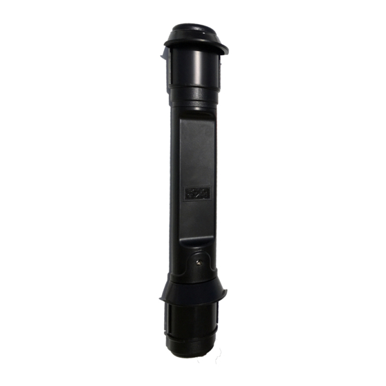
Page 2: Diagram Of Roboguard
Roboguard 2... -
Page 3: Installation
Roboguard, press any zone button to reset HQ – or see HQ Manual) Walk from left to right and back again in front of your Roboguard to ensure it is triggering the HQ. -
Page 4: Walk Test
(see picture). 3. The Roboguard will now buzz once for every time the bottom sensor detects, and twice for every time the top sensor detects. You should hear three ‘buzzes’... -
Page 5: Configuration
Roboguard 5 Roboguard Configuration Each Roboguard can be set up to work best in specific locations by activating different modes. The default setting is switch 1, ON, all others switches, OFF. The mode switches are located on the computer board inside the bottom sensor box. -
Page 6: Beam Range
Roboguard 6 SWITCH 4: SKINNY WINDOW MODE OFF = Roboguard will respond to vertical movement through the beams. It allows a second between breaking top and bottom beams to detect intruder. ON = This mode reduces that tolerance to a second thus allowing slow moving branches to break both beams without detecting intruder. -
Page 7: Minimising False Alarms
(See the ‘Roboguard Configuration’ section). 6. Use dog biscuits to run dogs through the beam array in walk-test mode to hear if the beams are set correctly. Please contact your local Roboguard dealer if you are not able to solve the problem. -
Page 8: Blocking Off Beams/Maintenance
Roboguard 8 Blocking off Beams Blocking off of beams is used to narrow the angle of view or to block moving objects such as palm fronds, to prevent false alarms. Blocking off of a beam is done by first, sliding down the fastener ring and removing the UV stable lens. -
Page 9: Battery Life
Align the white inner main lenses by carefully shifting them to one side or the other (only about 1mm of play). For better range you can mount your Roboguard at an angle to follow a roofline or sloping ground. -
Page 10: Exploded View Of Roboguard
Roboguard 10... -
Page 11: Bracket
The bracket can be mounted to any surface and allows the installer to swivel the Roboguard and aim the beams in the required direction. This is particularly usefull when setting up in walk-test mode as you can also aim the beams between obstacles or down a narrow alleyway. -
Page 12: Hq Diagram Of Hq
Roboguard 12... -
Page 13: Interpreting Your Hq
A. To re-set the light to solid green – press the zone button once to turn it OFF, and once again to turn it ON to solid green. B. If the Roboguard is connected in Mode B, re-setting as above will cause the HQ to emit a short low tone bark. - Page 14 Roboguard or follows the TX to another Roboguard. Replace the ‘offending’ CPU or TX with a known working product. Always keep a spare set of known working PIR’s (or a Demo Roboguard) with you for diagnostics. G. If all else fails, it is possible you have a ‘low range’ HQ. Always keep a known, working HQ with you for diagnostics.
-
Page 15: Program Mode A (Roboguard 1 - 4)
Roboguard 15 To program guards into the HQ, follow these steps: 1. Connect the Battery: NOTE: Your dealer may have done this already. This is also a good time to set your output ports – see program mode D. 2. Using the Allen key supplied, remove the 4 securing screws at the... -
Page 16: Program Mode B (Roboguard 5 - 8)
4. Press any Zone Button to return to Standby Mode (or the HQ will time-out in 20 seconds). 5. To program the next Roboguard, press and hold the HQ Tamper Button until you hear a beep. The Tamper light will burn solid red and the previously programmed Roboguard Zone (s) will burn solid green. -
Page 17: Program Mode C (Remotes)
(Once to turn the Zone off –disarm, once to turn the Zone back on – re-arm.) To Remove a Roboguard from a Zone: Enter program mode A or B, select the Zone to be removed and press the Status button. -
Page 18: Connecting A Siren
Roboguard 18 Zone 4: AUXILLARY - HQ emits a series of tones, used as a summons for Medical, Doorbell or for testing remotes. Select the appropriate zone. The zone light will burn solid green. Press and hold the button on your remote that you wish to use for this function. - Page 19 Roboguard 19 PROGRAM MODE D: OUTPUT PORT PROGRAMMING The HQ can be connected to your alarm panel using the ‘Tele-cable’ provided with your purchase. You can change the HQ outputs to the panel depending on the number of panel zones available to you.
- Page 20 If the Remote arm button is pressed for a second time the HQ will arm instantly. On entry, if a Roboguard is triggered the speaker will beep, but after 30 sec the siren and output switches will be triggered if not disarmed.
-
Page 21: Cloning A Remote Tx
Roboguard 21 Roboguard Remote TX For use with Roboguard Receivers All remotes have unique codes in all four of the coloured buttons To programme the remote into your receiver, follow the instructions in the receiver user manual. TO CLONE A REMOTE: Hold down the button on the slave remote. -
Page 22: Timer Operating Instructions
Roboguard 22 Timer Robo 5.8 Rev 1 Information Power: 12 – 16 volts DC Relay: Potential free, 10A Timer Operating Instructions The timer is an adjustable timer from 1 second to approximately 4 minutes. The trigger (TRG) input is negative. -
Page 23: Installation
Required Power Supply: 12V DC The keypad can control, supervise and monitor up to four Roboguards and two Roboguard remote buttons, with individual intruder detected, tamper and supervision LED’s, and optional audible warning sounds from the speaker output. The keypad has six highly configurable output switches to connect to other devices/systems. -
Page 24: Output Port Programming
1. To enter Roboguard programming mode: hold down the tamper button until a beep is heard and the red tamper LED is solid (ON) You are now in Roboguard programming mode (let go of the button now). Zone LED’s that already have Roboguards programmed into them will now be solid (ON). - Page 25 6. To erase a Roboguard follow step 1, then select the zone to be erased and press the status button. Press any zone to reset.
- Page 26 Roboguard 26 Output Port operation chart ZONE 1 ZONE 2 ZONE 3 ZONE 4 1,5,6 Guard 2 1,5,6 Guard 3 1,5,6 Guard 4 1,5,6 Tamper 1,5,6 Status Remote 1 Remote 2 Programming Sequence Determine the desired output configuration from the output port chart.
- Page 27 LED you must do the following: 1. Press and release the tamper button (tamper LED on, keypad is now in tamper detected display mode) 2. The zone LED for the Roboguard that has been tampered with will be solid (on).
- Page 28 1. Press and release the status button (status LED on, keypad is now in status condition display mode) 2. The zone LED for the Roboguard that is “in status” will be solid (on). 3. Press and release all solid (on) LED's so only the red status LED is 4.
-
Page 29: Urx Installation
Intruder, Auto-test and Remote Tx. (Intruder and Remote are the most common). Once the uRx has learned a roboguard code, every time it receives that radio signal, it will respond by triggering a connected device. This connected device may be an alarm system, a camera system, a siren, an SMS module, a timer relay - in fact any device capable of being triggered by an electronic signal. - Page 30 (Check for radio interference by observing the flashing of the RF LED. If the RF led is flashing brightly and continuously then you may have a problem with radio reception. Confirm this by transmitting from a roboguard product to see how the RF-led flashes for data reception). Wiring See wiring Diagram Below.
-
Page 31: Coding Output Port
Roboguard 31 Coding The device will learn any Roboguard code transmitted while in learn mode. Activate learn mode by using a conductor (like a screwdriver) to short out the program pads on the PCB. The program pads are located between the letter B and the 2-way DIPswitch on the PCB. -
Page 32: Wiring Diagram
The repeater comprises a Universal Receiver (uRx) wired to a Universal Transmitter (uTx). The uRx will pick up any roboguard signal, pass it on to the uTx and the signal will be re-transmitted 400 metres. The uTx can be configured to delay the re-transmission. Although not often used, this feature is important to determine if the repeater is working properly. - Page 33 Guard hut and the Roboguards are mounted at great distance or in obscure locations. The repeater can be used to improve the range of the Roboguard Remote. The uRx and uTx housing is not waterproof so the Repeater Station should be mounted under cover or in a suitable waterproof box if outdoors.
-
Page 34: Utx Installing A Repeater Station
Auto Test signal if it remains in the altered state; thereby monitoring functionality of the devices wired to it. (Auto test signals apply to Roboguard Code only) Switch 1 - ON (Default). In this mode the unit will function as a repeater station. -
Page 35: Programming Roboguard Or Remote Code
Switch 2 - OFF Normal operation. Switch 3 - OFF Causes the unit to transmit Roboguard Code during formatting. Will be programmed into an intruder zone on the receiver. Switch 3 - ON Causes the unit to transmit Remote Code during formatting. - Page 36 Select an input zone on your receiver (this can be a Keypad, HQ or a uRx/L – one zone only) by following the instructions in the manual. Note: Intruder zones on the receiver will only accept Roboguard Code and Remote zones on the receiver will only accept Remote Code.
- Page 37 This will stop the uTx from sending auto-test data from these zones. AUOTOTEST: The uTx will supervise the devices connected when in Roboguard Mode, but not in Remote Mode. If the device does not return to default state but remains in triggered state the uTx will fail Auto test on all receivers except the uRx.
-
Page 38: Led Indicator Wiring Diagram
LED INDICATOR Introduction The LED unit is used to visually indicate the status of the Roboguard system to a distant user. The idea is that the property owner can see whether the alarm has been triggered in their absence and can therefore proceed with caution if this is the case. - Page 39 The installation must be tested for compatibility with the siren as the siren control line is very noisy and may require additional filtering. Note: Intruder zones on the receiver will only accept Roboguard Code and Remote zones on the receiver will only accept Remote Code.
-
Page 40: Power Supply Wiring Diagram
The 12 volt power supply is used to supply 12 volts to Roboguard products. It is generally used to power a siren connected to a Roboguard HQ. It can also be used to supply power to the uRx, uTx or repeater station. - Page 41 Roboguard 41 Note: Set the HQ to have NO outputs. The LED’s on the power supply board should be OFF in the non triggered state. The Output of the power supply board has jumpers to make the outputs NO or NC. (This method greatly reduces the current consumption).
- Page 42 Roboguard 42 NOTES...
- Page 43 Roboguard 43 NOTES...
- Page 44 Roboguard 44 NOTES...
Need help?
Do you have a question about the TRX005 and is the answer not in the manual?
Questions and answers