Sign In
Upload
Download
Table of Contents
Contents
Add to my manuals
Delete from my manuals
Share
URL of this page:
HTML Link:
Bookmark this page
Add
Manual will be automatically added to "My Manuals"
Print this page
×
Bookmark added
×
Added to my manuals
Manuals
Brands
Myron L Manuals
Monitor
750 Series
User manual. installation, operation, maintenance
Myron L 750 Series User Manual. Installation, Operation, Maintenance
Resistivity monitors
Hide thumbs
1
Table Of Contents
2
3
4
5
6
7
8
9
10
11
12
13
14
15
16
page
of
16
Go
/
16
Contents
Table of Contents
Bookmarks
Table of Contents
Table of Contents
1 Introduction
Scope
Functional Descriptions
Monitor Applications
Monitor Specifications
Resistivity Cells
Cell Product Specifications
Optional Interface Features
How to Order
2 Installation
General
Mechanical Installation
Surface Installation
Panel Mounting
Cell Installation
Electrical Installation
Main Ac Power Installation
Cell Installation
Alarm Relay Installation
Optional Interface Connections
220 Vac Conversion
0-5/0-10 VDC Recorder Board
Ma and 420D TRANSMITTER BOARDS
3 Operating Procedures
General
Switch and Indicators Controls
Model 750
Model 752 and 753
Model 762
Operational Checkout Procedures
Model 750
Model 752, 753 and 762
4 Component Identification, Calibration and Preventive Maintenance
General
Primary Component Identification
Calibration Procedures
Meter Mechanical Zero Reading
Full Scale Calibration Procedures
Model 750
Models 752, 753 and 762
Internal Set Point Adjustment
0-5/0-10 VDC Recorder Board
MODEL 753 with 4-20Ma or 4-20D OPTION
Preventive Care
5 Appendix
Areplaceable Components Chart
Advertisement
Quick Links
1
Model 750
2
Calibration Procedures
Download this manual
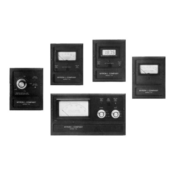
RESISTIVITY MONITORS
Installation • Operation• Maintenance
User Manual for Models 750
6115 Corte del Cedro
Carlsbad, CA 92009-1516 USA
Tel 760-438-2021
Fax 800-869-7668 / 760-931-9189
www.myronl.com
752
753
762
pH/Conductivity Instrumentation
Accuracy • Reliability • Simplicity
Table of
Contents
Previous
Page
Next
Page
1
2
3
4
5
Advertisement
Table of Contents
Need help?
Do you have a question about the 750 Series and is the answer not in the manual?
Ask a question
Questions and answers
Related Manuals for Myron L 750 Series
Monitor Myron L 760 Series User Manual. Installation, Operation, Maintenance
Resistivity monitors (16 pages)
This manual is also suitable for:
760 series
750
752
753
762
Table of Contents
Print
Rename the bookmark
Delete bookmark?
Delete from my manuals?
Login
Sign In
OR
Sign in with Facebook
Sign in with Google
Upload manual
Upload from disk
Upload from URL


Need help?
Do you have a question about the 750 Series and is the answer not in the manual?
Questions and answers