Table of Contents
Advertisement
Quick Links
Advertisement
Table of Contents

Subscribe to Our Youtube Channel
Summary of Contents for Wittenstein Alpha Premo SP Series
- Page 1 premo SP Line / TP Line / XP Line Operating Manual 4022-D045530 Revision: 02...
- Page 2 +90 216 709 21 23 WITTENSTEIN Güç Aktarma Sistemleri Tic. Ltd. Şti. Türkiye info@wittenstein.com.tr +90 216 709 21 23 Sistemleri Tic. Ltd. Şti. © WITTENSTEIN alpha GmbH 2019 Subject to technical and content changes without notice. 4022-D045530 Revision: 02...
-
Page 3: Table Of Contents
premo Contents About this manual ....................3 1.1 Signal words ......................3 1.2 Safety symbols.....................4 1.3 Design of the safety instructions ................4 1.4 Information symbols .....................4 Safety........................5 2.1 EU Low Voltage Directive ..................5 2.2 Dangers .......................5 2.3 Personnel ......................5 2.4 Intended use ......................5 2.5 Reasonably foreseeable misuse ................6 2.6 Guarantee and liability ..................6 2.7 General safety instructions ..................6... - Page 4 premo Appendix ......................26 9.1 Specifications for mounting on a machine............26 9.1.1 Specifications for mounting premo SP line ........... 26 9.1.2 Specifications for mounting premo TP line ........... 26 9.1.3 Specifications for mounting premo XP line ........... 26 9.2 Specifications for mounting on the output side..........27 9.2.1 Thread in output flange, premo TP line ............
-
Page 5: About This Manual
Contradictory specifications in this manual thereby become void. In case of questions on the special applications, please contact WITTENSTEIN alpha GmbH. The operator must ensure that these instructions are read through by all persons assigned to install, operate, or maintain the servo actuator, and that they fully comprehend them. -
Page 6: Safety Symbols
About this manual premo Safety symbols The following safety symbols are used to indicate possible hazards, prohibitions, and important information: General danger Hot surface Suspended loads Danger of being pulled in Electric voltage Flammable Harmful to the Information environment Component sensitive to electrostatic discharge Design of the safety instructions The safety instructions of these instructions are designed according to the following pattern:... -
Page 7: Safety
premo Safety Safety This operating manual, especially the safety instructions and the rules and regulations valid for the operating site, must be observed by all persons working with the servo actuator. In addition to the safety instructions in this manual, also observe any (legal and otherwise) applicable environmental and accident prevention rules and regulations (e.g. -
Page 8: Reasonably Foreseeable Misuse
- Operation of the servo actuator without lubricant - Operation of a heavily soiled servo actuator - Modifications or reconstructions that have been carried out without the approval of WITTENSTEIN alpha GmbH General safety instructions Faulty electrical connections or not approved, current-carrying components can cause serious injuries and even death. - Page 9 premo Safety Objects flung out by rotating components can cause serious injuries. Remove objects and tools from the servo actuator before putting it into operation. Rotating components on the servo actuator can pull in parts of the body and cause serious injuries and even death. Keep a sufficient distance to rotating machinery while the servo actuator ...
-
Page 10: Safety Signs
Safety premo Lubricants are flammable. Do not spray with water to extinguish. Suitable extinguishing agents are powder, foam, water mist and carbon dioxide. Observe the safety instructions of the lubricant manufacturer (see Chapter 7.4 "Information on the lubricant used"). Solvents and lubricants can cause skin irritations. -
Page 11: Description Of The Servo Actuator
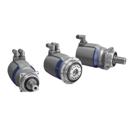
premo Description of the servo actuator Description of the servo actuator The servo actuator is a combination of a low- backlash planetary gearbox (B) and an AC servomotor (A). The AC servomotor is a brushless 3-phase synchronous motor with excitation by means of permanent magnets located on the rotor. -
Page 12: Name Plate
Description of the servo actuator premo Name plate The name plate is attached to the servo actuator housing. WITTENSTEIN alpha GmbH Mat.no.: 40000001-00-0 Walter-Wittenstein-Str. 1 | 97999 Igersheim SN: 1234567 [V]: 750 PBG 33FS-016FP01-6MKGTCW01 Ratio i: 16 DIN EN 60034-1... -
Page 13: Ordering Code
premo Description of the servo actuator Ordering code – – – ® premo Size Ratio Operating Pin assignment voltage See next page for options 5 = 320V 6 = 560V Orientation to flange Sector package Characteristic 0 = 0° G = General S = Standard 1 = 90°... -
Page 14: Performance Statistics
Straight integral socket, 2-cab EnDat 2.2 absolute, singleturn EnDat 2.2 absolute, multiturn HIPERFACE® absolute, singleturn Pin assignment options HIPERFACE® absolute, multiturn WITTENSTEIN alpha-Standard HIPERFACE DSL* Safety absolute, singleturn Temp. sensor in signal cable Siemens-compatible HIPERFACE DSL* Safety absolute, multiturn WITTENSTEIN alpha-Standard DRIVE-CliQ absolute, singleturn Temp. -
Page 15: Weight Of Premo Tp Line
premo Description of the servo actuator 3.4.2 Weight of premo TP line Weight [kg] Size of premo TP line Size 1 Size 2 Size 3 Without brake i = 16 – 35 10.5 i = 40 – 100 With brake i = 16 –... -
Page 16: Transport And Storage
Check the completeness of the delivery against the delivery note. Missing parts or damage must be notified immediately in writing to the carrier, the insurance company, or WITTENSTEIN alpha GmbH. Packaging The servo actuator is delivered packed in foil and cardboard boxes. -
Page 17: Assembly
premo Assembly Assembly Read the general safety instructions before beginning work (see Chapter 2.7 "General safety instructions"). Preparations Many electronic components are sensitive to electrostatic discharge (ESD). This particularly concerns integrated circuits (IC), semiconductors, resistors with a tolerance of less than one percent as well as transistors and other components such as encoders. -
Page 18: Mounting Premo Sp Line On A Machine
Assembly premo 5.2.1 Mounting premo SP line on a machine premo SP line and premo XP line are equipped with a square flange with round through-holes for mounting on a machine. Alternatively premo XP line can have slotted holes, see Chapter 5.2.3 "Mounting premo XP line with slotted holes on a machine (optional)". -
Page 19: Mounting Premo Xp Line With Slotted Holes On A Machine (Optional)
premo Assembly 5.2.3 Mounting premo XP line with slotted holes on a machine (optional) For adjusting the gearing backlash between output pinion and toothed rack / counter-wheel, premo XP line features slotted holes and guides on the sides as an option. An additional adjustment device is no longer necessary. -
Page 20: Components Mounted On The Output Side
Assembly premo Pinning the mounted and aligned servo actuator (optional) There are bore holes (B) on the housing for pinning the servo actuator to the machine. Drill pin holes into the machine base according to the bores (B) of the housing. Ream the bores to the corresponding fit size for ... -
Page 21: Installing Electrical Connections
premo Assembly Installing electrical connections Electrically live components may result in electric shocks if touched and can cause serious injuries and even death. Observe the five safety rules of electrical engineering before starting electrical installation work: - Disconnect. - Secure against being switched on again. - Check that there is no voltage. -
Page 22: Startup And Operation
premo Startup and operation Startup and operation Safety instructions and operating conditions Read the general safety instructions before beginning work (see Chapter 2.7 "General safety instructions"). Wearing hearing protection in the vicinity of the servo actuator is recommended. Improper use can cause damage to the servo actuator. -
Page 23: Maintenance And Disposal
premo Maintenance and disposal Maintenance and disposal Read the general safety instructions before beginning work (see Chapter 2.7 "General safety instructions"). The permanent magnets of the stator send a strong magnetic field, which becomes active during the disassembling of the servo actuator. Observe the general safety instructions (e.g. -
Page 24: Visual Inspection
Maintenance and disposal premo 7.1.2 Visual inspection Check the entire servo actuator and all cables for exterior damage. The radial shaft seals are subject to wear. Therefore, also check the servo actuator for leakage during each visual inspection (lubricant leaks). ... -
Page 25: Maintenance Schedule
premo Maintenance and disposal Maintenance schedule Maintenance work At startup After the first 500 Every 4 Yearly operating hours or 3 weeks months Refreshment of holding brake Visual inspection and cleaning Checking the tightening torques Tbl-8: Maintenance schedule Information on the lubricant used All servo actuators are permanently lubricated by the manufacturer with synthetic gear oil (polyglycols) of viscosity class ISO VG100, ISO VG220 or with a high-performance lubricant (see type plate). -
Page 26: Malfunctions
premo Malfunctions Malfunctions Changed operational behavior can be an indication of existing damage to the servo actuator, or cause damage to the servo actuator. Do not put the servo actuator back into operation until the cause of the malfunction has been rectified. Rectifying of malfunctions may only be done by specially trained technicians. - Page 27 Malfunctions premo Fault Possible cause Solution Brake does not Voltage drop along the Ensure that the supply voltage is release supply line > 10% correct. Check the cable cross- section. Incorrect brake connection Check the connection for correct polarity and voltage Short circuit in the coil or at Consult our Customer Service body of brake coil...
-
Page 28: Appendix
Appendix Appendix In case of questions on the special applications, please contact WITTENSTEIN alpha GmbH. Specifications for mounting on a machine 9.1.1 Specifications for mounting premo SP line Through-holes in servo actuator housing of premo SP line Size Hole circle Ø... -
Page 29: Specifications For Mounting On The Output Side
Appendix premo Specifications for mounting on the output side 9.2.1 Thread in output flange, premo TP line Type/Size Hole circle Ø Quantity x Thread Tightening torque x Depth [mm] [Nm] [ ] x [mm] x [mm] Property class 12.9 Size 1 31.5 8 x M5 x 7 Size 2... -
Page 30: Technical Specifications
premo Appendix Technical specifications 9.4.1 Motor specifications, premo 320 V This chapter gives you the technical data of the engine being used. The complete technical data of the servo actuators can be found in the data sheet of the actuator. The permissible output specifications of the actuator are influenced by the gearbox and lubricant being used. -
Page 31: Motor Specifications, Premo 560 V
Appendix premo 9.4.2 Motor specifications, premo 560 V This chapter gives you the technical data of the engine being used. The complete technical data of the servo actuators can be found in the data sheet of the actuator. The permissible output specifications of the actuator are influenced by the gearbox and lubricant being used. -
Page 32: Technical Specifications For Resolver
premo Appendix 9.4.3 Technical specifications for resolver Resolver Ordering code PxG xxxx-xxxxxxx-xRxxxxxxx-xxx Size Size 15 Type TS2620N21E11 Pole pair number Input voltage 10kHz Transmission ratio 0,5±5% Fault ± 10'max Zero voltage 20mV Phase shift 0° nominal Impedance ZR0 70 + j 100 ohm Impedance ZS0 180 + j 300 ohm Impedance ZSS... -
Page 33: Technical Specifications Of Hiperface Dsl Absolute Encoder Singleturn
Appendix premo 9.4.6 Technical specifications of Hiperface DSL absolute encoder Singleturn Hiperface DSL absolute encoder Singleturn Ordering code PxG xxxx-xxxxxxx-xGxxxxxxx-xxx Type EKS36 Operating voltage 7-12 V Interface Hiperface DSL Number of SinCos periods per revolution – Resolution per revolution 1.048.576 (20 bit) Number of Multiturn revolutions –... -
Page 34: Technical Specifications Of Endat 2.1 Absolute Encoder Multiturn
premo Appendix 9.4.9 Technical specifications of EnDat 2.1 absolute encoder Multiturn EnDat 2.1 absolute encoder Multiturn Ordering code PxG xxxx-xxxxxxx-xMxxxxxxx-xxx Type EQN 1125 Operating voltage 3.6-14 V Interface Endat 2.2 / EnDat01 Number of SinCos periods per revolution Resolution per revolution 8192 (13 bit) Number of Multiturn revolutions 4096 (12 bit) -
Page 35: 12Technical Specifications Of Drive-Cliq Absolute Encoder Singleturn
Appendix premo 9.4.12 Technical specifications of DRIVE-CLiQ absolute encoder Singleturn DRIVE-CLiQ absolute encoder Singleturn Ordering code PxG xxxx-xxxxxxx-xLxxxxxxx-xxx Type ECN 1324S Operating voltage 10 - 36 V Interface DRIVE-CLiQ Number of SinCos periods per revolution – Resolution per revolution 16.777.216 (24 bit) Number of Multiturn revolutions –... -
Page 36: 15Technical Specifications Of Hiperface Absolute Encoder Multiturn (Compatible With Rockwell)
premo Appendix 9.4.15 Technical specifications of Hiperface absolute encoder Multiturn (compatible with Rockwell) Hiperface absolute encoder Multiturn (compatible with Rockwell) Ordering code PxG xxxx-xxxxxxx-xVxxxxxxx-xxx Type SKM36S Operating voltage 7 – 12 V Interface Hiperface Number of SinCos periods per revolution Resolution per revolution 4096 (12 bit) Number of Multiturn revolutions... -
Page 37: 18Technical Specifications Heidenhain Incremental
Appendix premo 9.4.18 Technical specifications Heidenhain Incremental Heidenhain Incremental Ordering code PxG xxxx-xxxxxxx-xIxxxxxxx-xxx Type ERN 1185 Operating voltage Interface Incremental interface Number of SinCos periods per revolution 2048 Resolution per revolution – Number of Multiturn revolutions – SIL level – Tbl-33: Technical specifications Heidenhain Incremental 9.4.19 Technical specifications temperature sensors KTY and PT 1000 Type... -
Page 38: 20Technical Specifications Of Ptc Temperature Sensor
premo Appendix Type KTY 84-130 PT 1000 Ordering PxG xxxx-xxxxxxx- PxG xxxx-xxxxxxx- code: xxKxxxxxx-xxx xxTxxxxxx-xxx Temperature Resistance, type Resistance, type [°C] [kohm] [Ohm] 1.482 1647.72 1.560 1684.78 1.640 1721.73 1.722 1758.56 Tbl-34: Technical specifications of KTY, NTC and PT 1000 temperature sensors 9.4.20 Technical specifications of PTC temperature sensor PTC STM 160 Ordering code: PxG xxxx-xxxxxxx-xxPxxxxxx-xxx... -
Page 39: 21Technical Specifications Of Premo Brake
Appendix premo 9.4.21 Technical specifications of premo brake The holding brake used is not a safety brake and is not suitable for personal protection or as a service brake. The brakes installed in the actuators work on the basis of a permanent magnetic circuit. When the power is off, the brake pads make contact and a holding torque is built up. -
Page 40: 22Pin Assignment 1
premo Appendix 9.4.22 Pin assignment 1 Design with resolver — output (pin assignment 1) Intercontec mounting socket, series production 923, 6-pin, contact pin Ø 2mm View of plug side of actuator Function Earth conductor Brake + (optional) Brake – (optional) Tbl-37: Design with resolver —... - Page 41 Appendix premo Option "N" and "K" — signal (pin assignment 1) Intercontec mounting socket, series production 623, 12-pin P, contact pin Ø 1mm View of plug side of actuator Function REFCOS Data + Temp + Temp - REFSIN Data - n.c.
- Page 42 premo Appendix Option "F" and "W" — signal (pin assignment 1) Intercontec mounting socket, series production 623, 17-pin E, contact pin Ø 1mm View of plug side of actuator Function n.c. n.c. data n.c. clock n.c. M- Encoder (0V) n.c. n.c.
-
Page 43: 23Pin Assignment 2
Appendix premo 9.4.23 Pin assignment 2 Design with resolver and EnDat encoder — output (pin assignment 2) Intercontec mounting socket, series production 923, 6-pin, contact pin Ø 2mm View of plug side of actuator Function Earth conductor Brake + (optional) Brake –... -
Page 44: 24Pin Assignment 4
premo Appendix Option "S" and "M" — signal (pin assignment 2) Intercontec mounting socket, series production 623, 17-pin E, contact pin Ø 1mm View of plug side of actuator Function data n.c. clock n.c. M- Encoder (0V) Temp + Temp - P- Encoder (U data* clock*... - Page 45 Appendix premo Option "R" — signal (pin assignment 4) Intercontec mounting socket, series production 623, 12-pin P, contact pin Ø 1mm View of plug side of actuator Function Cos/S1 Cos-low/S3 Sin/S2 Sin-low/S4 n.c. n.c. Ref/R1 Ref-low/R2 Screen n.c. n.c. n.c. Tbl-48: Option "R"...
- Page 46 premo Appendix Option "S" and "M" — signal (pin assignment 4) Intercontec mounting socket, series production 623, 17-pin E, contact pin Ø 1mm View of plug side of actuator Function data n.c. clock n.c. M- Encoder (0V) n.c. n.c. P- Encoder (U data* clock* M- Sense (0V- Sense / Sensor 0V)
-
Page 47: 25Pin Assignment 5
Appendix premo Option "F" and "W" — signal (pin assignment 4) Intercontec mounting socket, series production 623, 17-pin E, contact pin Ø 1mm View of plug side of actuator Function n.c. n.c. data n.c. clock n.c. M- Encoder (0V) n.c. n.c. - Page 48 premo Appendix Option "E" and "V" — signal (pin assignment 5) Intercontec mounting socket, series production 623, 17-pin E, contact pin Ø 1mm View of plug side of actuator Function SIN + SIN - COS + COS - Data + Data - n.c.
-
Page 49: 26Pin Assignment 6
Appendix premo 9.4.26 Pin assignment 6 Design with resolver and optical encoder — output (pin assignment 6) Intercontec mounting socket, series production 923, 8-pin E, contact pin 4x2mm + 4x1mm View of plug side of actuator Function Earth conductor Temp + Temp - Brake + (optional) Brake - (optional) - Page 50 premo Appendix Option "S" and "M" — signal (pin assignment 6) Intercontec mounting socket, series production 623, 17-pin E, contact pin Ø 1mm View of plug side of actuator Function P- Sense (5V-Sense / Sensor U n.c. n.c. M- Sense (0V- Sense / Sensor 0V) n.c.
-
Page 51: 27Pin Assignment 8
Appendix premo 9.4.27 Pin assignment 8 Design with optical encoder — output (pin assignment 8) Intercontec mounting socket, series production 923, 8-pin E, contact pin 4x2mm + 4x1mm View of plug side of actuator Function Brake + (optional) Brake - (optional) Temp + Temp - Earth conductor... -
Page 52: 28Pin Assignment 9
premo Appendix 9.4.28 Pin assignment 9 Option "G" and "H" — output/signal (pin assignment 9) Intercontec mounting socket, series production 923, 9-pin E, contact pin 4x2mm + 5x1mm View of plug side of actuator Function Earth conductor GND / DSL - Screen Brake + (optional) Us / DSL +... - Page 53 premo Revision history Revision Date Comment Chapter 31.01.17 New version 02.01.19 Product lines, 2, 3, 5, 9 Safety information, Technical specification, Plug connection Revision: 02 4022-D045530...
- Page 54 WITTENSTEIN alpha GmbH ꞏ Walter-Wittenstein-Straße 1 ꞏ 97999 Igersheim ꞏ Germany Tel. +49 7931 493-12900 ꞏ info@wittenstein.de WITTENSTEIN ‒ with the future www.wittenstein-alpha.de AC: XXXXXXXX 4022-D045530Revision: 02...
Need help?
Do you have a question about the Premo SP Series and is the answer not in the manual?
Questions and answers