Table of Contents
Advertisement
Advertisement
Table of Contents

Related Manuals for Howard Industries HI-105

Summary of Contents for Howard Industries HI-105
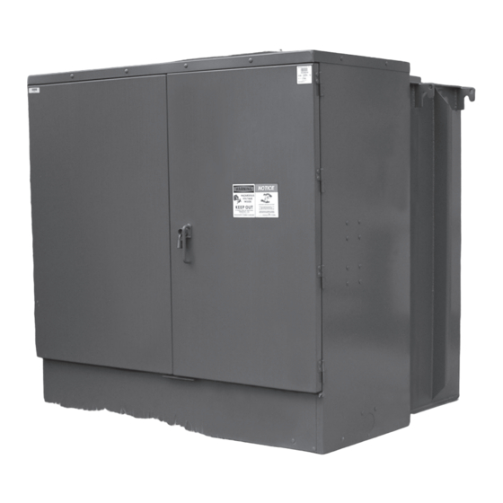
- Page 1 Document 2.4.126, Revision 4 Three-Phase Padmounted Distribution Transformers October 2017 Instructions (HI-105) Installation, Operation, and Maintenance of Three-Phase Padmounted Distribution Transformers 45 kVA through 10,000 kVA Howard Industries Distribution Transformer Division...
-
Page 2: Important Safety Information
Although efforts have been made to ensure accuracy and completeness, these instructions do not address every conceivable application or circumstance that might be encountered. Howard Industries makes no representation or warranty with respect to, and assumes no responsibility for the completeness, accuracy, sufficiency, or usefulness of, these instructions. -
Page 3: Table Of Contents
Document 2.4.126, Revision 4 Three-Phase Padmounted Distribution Transformers October 2017 TABLE OF CONTENTS Important Safety Information........................2 Section 1: Introduction..........................5 Section 2: Receiving, Handling and Storage....................….6 Drawings and Documents......................…..6 Lifting and Handling........................…..6 Initial Inspection...........................….6 Fluid Level............................….7 Internal Inspection.........................….7 Fluid Sampling..........................7 Transformer Storage........................….8 Section 3: Installation..........................9 Lifting and Handling.........................9 Jacking, Skidding and Rolling......................9... - Page 4 Document 2.4.126, Revision 4 October 2017 Three-Phase Padmounted Distribution Transformers Internal Weak-Link Cartridge Fuse……………………………………………............17 Bay-O-Net Fuse…………………………………………………………………..............17 Dead-Break Dry-Well Canister Fuse……………………………………………............18 Internal Partial-Range Current-Limiting Fuse………………………………….............19 S&C Arc-Strangler………………………………………………………………..............19 S&C Fused Switch………………………………………………………………...............19 Vacuum Fault Interrupter……………………………………………………….............19 Surge Arresters………………………………………………………………..............20 Internal MOV Surge Arresters……………………………………………............…..….20 Molded-Case Circuit Breakers………………………………………………............…21 Hot-Stick Operable Devices……………………………………………………............
-
Page 5: Section 1: Introduction
SECTION 1: INTRODUCTION This document is intended as a general guide for the installation, operation and maintenance of Howard Industries three-phase compartmental padmounted distribution transformers. Although efforts have been made to ensure accuracy and completeness, these instructions do not address every conceivable application or circumstance that might be encountered. -
Page 6: Section 2: Receiving, Handling And Storage
Note any damage or discrepancies on the bill of lading, file a claim with the carrier, and notify the Howard Industries WARNING Transformer Division prior to unloading the transformer and before attempting any repair. -
Page 7: Fluid Level
If moisture or contaminates in the does not have a fluid level gauge or sight plug, the fluid is suspected, contact the Howard Industries fluid level can be checked by removing the liquid Transformer Division immediately for instructions. -
Page 8: Transformer Storage
Document 2.4.126, Revision 4 October 2017 Three-Phase Padmounted Distribution Transformers Transformer Storage Transformers may be temporarily stored if properly prepared. It is recommended that transformers be stored completely assembled. Prior to storage, transformers should be thoroughly inspected as described above in the “Initial Inspection” section. If the transformer is not completely assembled, separate components and accessories should be stored in a clean dry area in their original shipping... -
Page 9: Section 3: Installation
Refer to the transformer nameplate for operation in conditions other than usual to determine the total weight of the assembled service conditions. Contact the Howard Industries transformer. Special care must be taken when Transformer Division, if additional information is... -
Page 10: Verifying Enclosure Integrity
Connections must be tightened appropriately to area. Such modifications of may void the warranty. prevent overheating and possible failure of the Consult with the Howard Industries Transformer connection. Refer to the nominal torque guidelines Division before making any modifications to the contained in Table 3. -
Page 11: Low-Voltage Connections
Document 2.4.126, Revision 4 Three-Phase Padmounted Distribution Transformers October 2017 Low-Voltage Connections Three-phase padmounted transformers are normally supplied with externally-clamped molded low-voltage bushings, with or without spade terminals. -
Page 12: Section 4: Inspection And Testing Before And After Initial Energization
Document 2.4.126, Revision 4 October 2017 Three-Phase Padmounted Distribution Transformers SECTION 4: INSPECTION AND TESTING BEFORE AND AFTER INITIAL ENERGIZATION Pre-Energization Inspection and Tests DANGER After the transformer has been installed, but before it is energized, the following tests and checks should be performed at a minimum to ensure that the transformer is ready to be energized. -
Page 13: Series/Multiple Or Delta/Wye Switch Settings
Document 2.4.126, Revision 4 Three-Phase Padmounted Distribution Transformers October 2017 Series/Multiple or Delta/Wye Switch Accessory Wiring—Check wiring of control Settings—Check series/multiple and delta/ and alarm circuits (if supplied) to make wye switch settings to make sure they are sure there are no loose connections and no set to the correct position. -
Page 14: Post-Energization Inspection And Tests
Document 2.4.126, Revision 4 October 2017 Three-Phase Padmounted Distribution Transformers Post-Energization Inspection and Tests Verifying Correct Voltage—Before supplying After the transformer is energized, the following voltage from the transformer to the load, tests and inspections should be performed. verify that the secondary voltage is correct. Using a suitable AC voltmeter, measure the voltage of the secondary windings and make sure they agree with the secondary voltages... -
Page 15: Section 5: Operation Of Switching And Protective Devices
Document 2.4.126, Revision 4 Three-Phase Padmounted Distribution Transformers October 2017 SECTION 5: OPERATION OF SWITCHING AND PROTECTIVE DEVICES The following operating instructions and descriptions of switching and fusing devices are DANGER intended to be a general guide for operation of Howard three-phase padmounted transformers in FAILURE TO FOLLOW THE INSTRUCTIONS BELOW normal environments. -
Page 16: Series/Multiple Or Delta/Wye Switch
Document 2.4.126, Revision 4 October 2017 Three-Phase Padmounted Distribution Transformers The tap changer is operated by use of a rotating the high-voltage compartment. These switches can handle located inside the terminal compartment. be either two-position (ON-OFF) switches or three- Never operate a de-energized tap changer while the or four-position sectionalizing switches. -
Page 17: Internal Weak-Link Cartridge Fuse
Document 2.4.126, Revision 4 Three-Phase Padmounted Distribution Transformers October 2017 Bay-O-Net Fuse A Bay-O-Net is a fluid-immersed, draw-out, dead- DANGER front, single-pole fused disconnect device that is rated for load-break operation. It is designed to be operated with a live-line tool (hot stick or shotgun FAILURE TO FOLLOW THE INSTRUCTIONS stick) and should not be operated by hand. -
Page 18: Dead-Break Dry-Well Canister Fuse
Document 2.4.126, Revision 4 October 2017 Three-Phase Padmounted Distribution Transformers The following procedure should be used to operate Dead-Break Dry-Well Canister Fuse a Bay-O-Net fuse device. Open both compartment The dead-break dry-well canister is a fluid-tight, doors and engage the prop rods on each door to single-pole, current-limiting fuse holder. -
Page 19: Internal Partial-Range Current-Limiting Fuse
Document 2.4.126, Revision 4 Three-Phase Padmounted Distribution Transformers October 2017 Re-Insert Fuse Holder—Re-insert the fuse holder DANGER using the following procedure. Attach a live-line tool to the hook eye. Insert the fuse holder into the housing. FAILURE TO FOLLOW THE INSTRUCTIONS BELOW WILL RESULT IN DEATH OR SERIOUS Push the fuse holder in firmly until the INJURY, AND DAMAGE TO THE EQUIPMENT. -
Page 20: Surge Arresters
Document 2.4.126, Revision 4 October 2017 Three-Phase Padmounted Distribution Transformers Surge Arresters Optional arrester disconnectors provide a means Surge arresters can be used in three-phase to disconnect the fluid-immersed MOV arrester padmounted transformer installations to protect the grounds for transformer testing without entering transformer and underground cable from damage the transformer tank. -
Page 21: Molded-Case Circuit Breakers
Transformers may be supplied with switching and transformer tank. fusing devices not discussed in these instructions. In such cases, contact the Howard Industries MOV arresters can be manually disconnected using the following procedure. Transformer Division or the device manufacturer for instructions. -
Page 22: Section 6: Operation Of Bushings, Gauges And Accessory Devices
Document 2.4.126, Revision 4 October 2017 Three-Phase Padmounted Distribution Transformers SECTION 6: OPERATION OF BUSHINGS, GAUGES AND OTHER ACCESSORY DEVICES Many of the accessory devices described below are Fluid Level Gauge and Sight Plug optional and may not be present in any particular The fluid level gauge is a dial-type device that transformer design. -
Page 23: Automatic Pressure Relief Device
Document 2.4.126, Revision 4 Three-Phase Padmounted Distribution Transformers October 2017 terminal compartment at the bottom of the front WARNING panel. Refer to “Sampling and Testing the Fluid” and “Draining and Filling the Tank” for the fluid sampling and draining procedures. FAILURE TO FOLLOW THE INSTRUCTIONS BELOW MAY RESULT IN DEATH OR SERIOUS Automatic Pressure Relief Device... -
Page 24: Low-Voltage Bushings
Other Accessory Devices WARNING Transformers may be supplied with accessory devices not discussed in these instructions. In such cases, contact the Howard Industries Transformer CT leads must be connected to a load or Division for information. short-circuited and grounded before the transformer is energized to avoid hazardous voltage at the CT terminals. -
Page 25: Section 7: Maintenance
Document 2.4.126, Revision 4 Three-Phase Padmounted Distribution Transformers October 2017 SECTION 7: MAINTENANCE WARNING WARNING FAILURE TO FOLLOW THE INSTRUCTIONS The transformer must be de-energized BELOW MAY RESULT IN DEATH OR SEVERE before performing any maintenance PERSONAL INJURY, AND /OR DAMAGE TO work. -
Page 26: Inspection Checklist
Document 2.4.126, Revision 4 October 2017 Three-Phase Padmounted Distribution Transformers pressure test according to the instructions in “Pre-energization Inspection and Tests.” WARNING Add fluid as necessary to ensure that the proper fluid level is maintained. Repair as FAILURE TO FOLLOW THE INSTRUCTIONS necessary. -
Page 27: Electrical Tests
Document 2.4.126, Revision 4 Three-Phase Padmounted Distribution Transformers October 2017 Inspection Checklist (cont.) Electrical Tests The following tests can be used to determine connections and tighten as necessary the condition of the transformer. Comply with (Refer to torque guidelines contained in instructions and precautions provided by the test Tables 1 through 4). -
Page 28: Exterior Paint Finish
Touch-up paint is available in aerosol cans examine the tank and fittings for leaks. Leaks above from the Howard Industries Transformer Division. the fluid level can be detected by applying soap solution to all welds, joints, pipe fittings, and cable Fluid Leaks connections. -
Page 29: Molded-Case Circuit Breakers
Document 2.4.126, Revision 4 Three-Phase Padmounted Distribution Transformers October 2017 voltage level and sinusoidal purity, load conditions When filtering any particular type of insulating and acoustic conditions at the installation site. fluid, make sure the filter press system is not Unusual sounds should be investigated, as this contaminated with any other type of fluid. -
Page 30: Opening The Transformer Tank
Document 2.4.126, Revision 4 October 2017 Three-Phase Padmounted Distribution Transformers Pump from the bottom of temporary storage Transformer tanks should not remain open for more container. To prevent bubbles in the fluid, than two hours. If work is interrupted, the tank do not allow air to enter the pump intake. -
Page 31: Torque Guidelines
Document 2.4.126, Revision 4 Three-Phase Padmounted Distribution Transformers October 2017 2. Re-install the hand-hole cover. Re- install fasteners according to the torque recommendations in Table 1. After tightening all fasteners, re-torque each one to ensure proper torque. 3. Pressurize the headspace to 3-4 PSIG and check for fluid leaks. - Page 32 Document 2.4.126, Revision 4 October 2017 Three-Phase Padmounted Distribution Transformers Table 3: Torque Guidelines for External Bushing Terminal Connections Terminal Type Nominal Torque (in-lbs) Torque Range (in-lbs) High-voltage molded bushing insert 170-190 High-voltage porcelain bushing eye-bolt 180-240 High-voltage porcelain bushing end cap 156-180 Low-voltage bushing, 5/8”...
-
Page 33: Additional Maintenance Instructions
Comply with all local, state and federal regulations when disposing of any insulating fluid. Fluid type and volume can be determined by referring to the transformer nameplate. Contact Howard Industries to obtain the appropriate fluid Safety Data Sheet (SDS). The SDS identifies fluid composition and properties, and describes important safety, handling and storage, ecological, regulatory, disposal and other pertinent information. - Page 34 NOTES Document 2.4.126, Revision 4 October 2017 Three-Phase Padmounted Distribution Transformers...
- Page 35 NOTES Document 2.4.126, Revision 4 Three-Phase Padmounted Distribution Transformers October 2017...
- Page 36 Three-Phase Padmounted Distribution Transformers HI-105 Instructions for Installation, Operation and Maintenance of Three-Phase Padmounted Distribution Transformers, 45 kVA through 10,000 kVA Document 2.4.126, Revision 4, October 2017 Copyright © 2017, Howard Industries, Inc. Laurel, Mississippi Telephone: 601-425-3151 Fax: 601-649-8090 Email: mkt@howard.com Web: howardtransformers.com...
Need help?
Do you have a question about the HI-105 and is the answer not in the manual?
Questions and answers