
Related Manuals for Modern Predator

Summary of Contents for Modern Predator
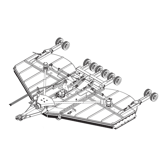
- Page 1 20' PREDATORRR CUTTER 20’ PREDATOR Operator’s Manual Operator’s Manual YOU'RE ALWAYS AHEAD...WITH A MODERN BEHIND. P.O. BOX 790 • BEAUMONT, TX 77704 409.833.2665 • 1.800.231.8198 FAX: 409.726.8333 www.modernusa.com Go Galvanized! 20’ Predator...
- Page 2 When ordering parts for the gear boxes and the drivelines, be sure to specify the serial number. The serial number is located outside the right tongue attaching plate on the center mainframe section. all times. information, and mail promptly. Be sure to give the serial number of this cutter. 20’ Predator...
- Page 3 Indicates an imminently hazardous situation that, if not avoided, COULD result in DEATH OR SERIOUS INJURY. CAUTION Indicates an imminently hazardous situation that, if not avoided, MAY result in MINOR INJURY. damage to, or destruction of the machine, attachments or the environment. 20’ Predator...
- Page 4 SAFETY SECTION 20’ Predator...
- Page 5 Serious injury or death to the operator or others could 20’ Predator...
- Page 6 Ensure slip clutches are properly adjusted to prevent excessive slippage and plate heating. · Never allow clippings or debris to collect near drivelines, slip clutches, and gearboxes. repairs. Use gloves and eye protection when servicing hot components. Contact with a hot 20’ Predator...
- Page 7 Serious injury and possible death could occur from not maintaining this implement and tractor in good operating condition. • Do not operate implement if excessive vibration exists. Shut down PTO and the tractor engine. Inspect the implement to determine the source of the vibration. If implement blades are missing 20’ Predator...
- Page 8 • Do not operate or pull the implement into standing water. When uplift or fan type implement resulting in serious boldly injury to the operator or bystanders. • Do not mow with two machines in the same area except with cab tractors with the windows closed. 20’ Predator...
- Page 9 • This implement is wider than the tractor. Be careful when operating or transporting this concrete abutments or other solid objects. Such an impact could cause the implement and tractor to pivot violently resulting in loss of steering control, serious injury, or even death. Never allow the implement to contact obstacles. 20’ Predator...
- Page 10 Such a situation is extremely hazardous and could result in serious object from the site. Never allow the cutting blades to contact such items. serious hazard and could cause serious injury or even death from objects thrown from the blades. 20’ Predator...
- Page 11 PTO by pushing the PTO into the tractor and through the personal injury. • On a fully-assembled unit, do not remove the Wing Retaining Strap until hoses are attached to bystanders away during operations. injury or even death. 20’ Predator...
- Page 12 Determine the maximum transport speed not to you determine that it is safe to operate at a higher speed. Use extreme care and reduce your speed when turning sharply to prevent the tractor and implement from turning over. Determine ground. 20’ Predator...
- Page 13 10 feet of any power line. Maintenance and Service Safety • Periodically inspect all moving parts for wear and replace when necessary with authorized sure all pins have cotter pins and washers. Serious injury may occur from not maintaining this 20’ Predator...
- Page 14 See your Authorized Dealer for proper repairs. material may release fumes which can be harmful to your health. • Do not modify or alter this implement. Do not permit anyone to modify or alter this implement, any of its components or any implement function. 20’ Predator...
- Page 15 Safety Signs/Decals • Modern Ag supplies safety decals on this product to promote safe operation. Damage to the decals may occur while in shipping, use, or reconditioning. Always maintain the safety signs in good readable condition. If the safety signs are missing, damaged, or unreadable, obtain and install replacement safety signs immediately.
- Page 16 11 ..490-1022 ..CAUTION REPLACE SHIELDS ..1 See next page for additional cutter decals. MORE DECALS ON NEXT PAGE 20’ Predator...
- Page 17 14 ..490-4100 ... .1000 RPM ..... .1 15 ..490-9020 ... .TYPICAL SET-UP ....1 490-FEMA 20’ Predator...
- Page 18 OPERATION SECTION 20’ Predator...
- Page 19 Safety Messages. Always use good common sense to avoid hazards. PELIGRO PELIGRO Si no lee ingles, pida ayuda a alguien que si lo lea para que le traduzca las medidas de seguridad. 20’ Predator...
- Page 20 Hydraulic Level Lift ....Standard (Super) • Option (Dragon) ... . Standard Front chains and rear rubber guards are standard equipment. Single and rear chain guards are available as extra purposes. 20’ Predator...
- Page 21 Tractor or Implement, an operator on prescription or over-the-counter medication must consult a medical professional regarding any side effects of the medication that Serious injury or death to the operator or others could result if the operator is under 20’ Predator...
- Page 22 Slow Moving Vehicle (SMV) emblem which are clearly visible from the Always replace shields and guards that were removed for access to connect, service, or repair the tractor or cutter. Never operate the tractor PTO with the PTO master shield missing or in the raised position. 20’ Predator...
- Page 23 (Not available on 1000 RPM 1-3/4”-20 cutters) Set drawbar length measured from PTO shaft end to hitch hole at 14” for 540 and 16” for 1000 RPM otherwise the drivelines will not phase properly, possibly causing damage to your machine. 20’ Predator...
- Page 24 If operating an older model tractor where the tractor’s transmission and PTO utilize one master clutch, an over-running clutch must be used between the PTO output shaft and the driveline of the cutter. An authorized tractor dealer can provide the over-running clutch and its installation if needed. 20’ Predator...
- Page 25 If any part of either manual is not completely understood, consult an authorized dealer for a complete explanation. WARNING Do not mount the Tractor while the tractor is moving. Mount the Tractor only when the Tractor and all moving parts are completely stopped. (SG-12) 20’ Predator...
- Page 26 DANGER and wait for all moving parts to stop. Place the tractor shift lever into a low range is moving or while the engine is running. Operate the Tractor controls from the tractor seat only. 20’ Predator...
- Page 27 Use extreme caution when connecting the cutter to the tractor. The cutter should be securely resting at points between the tractor hitch arms and cutter pins. DANGER you or anyone else attempts to connect or disconnect the Implement and Tractor hitches. (S3PT-15) 20’ Predator...
- Page 28 With the tractor shut down and secured in position, relieve hydraulic pressure from the tractor by moving the Never leave a disconnected hose end open and cap the tractor hydraulic outlet ports when not in use. If the tractor ports or cutter hydraulic hose ends become contaminated, wipe clean with a rag before connecting. 20’ Predator...
- Page 29 Ensure the valve matches the hydraulic operating system of the tractor (open or closed center). Refer valve. and outlet lines to outlets of the same tractor hydraulic port. Connect the cutter hydraulics to the the control valve positioned to correspond with the left and right wing. 20’ Predator...
- Page 30 LEVELING DECK CENTER SECTION 1. Place the tractor and cutter on a level surface and lower both wings. 2. Using the center section hydraulic cylinder, position are approximately 2” off the ground. 3. Shut down the tractor, place the transmission in 20’ Predator...
- Page 31 3/4” lower in the front that than the rear. To lower the front, lengthen the leveling rods and to raise the front shorten the leveling rods. IMPORTANT: Adjust 20’ Predator...
- Page 32 When attaching the Implement input driveline to the Tractor PTO, it is important that the connecting groove on the Tractor PTO shaft. A driveline not attached correctly to the Tractor PTO shaft could come loose and result in personal injury and damage to the Implement. (S3PT-17) 20’ Predator...
- Page 33 NOT TURNING, slowly drive the tractor with the cutter attached through the most severe terrain conditions expected and watch shaft movement. shield becomes less than 2” at any point thereis a potential problem bottoming out the driveline and the driveline should be shortened. 20’ Predator...
- Page 34 If the engaged length is less than 12” for a CV driveline and less than 6” for a non-CV driv eline, the shaft is considered too short and should be replaced with a longer shaft. Consult an be made aware of terrain conditions and avoid situations which pose a potential problem to avoid damaging the driveline. 20’ Predator...
- Page 35 Move the tractor rear tires wider apart to limit the tractor turning radius. Position the cutter at multiple angles and perform the above procedure. Determine the sharpest turning radius that maintains a safe operating angle and note this position to the operator. 20’ Predator...
- Page 36 DO NOT approach the Implement unless the Tractor is turned or inadvertent fall by any of these components could cause serious injury or even death. WARNING Periodically inspect all moving parts for wear and replace when necessary with P i di ll i t ll 20’ Predator...
- Page 37 (SGM-3) HARDFACING ON BLADES SINCE THIS WILL LIKELY CRACK OR OTHERWISE DAMAGE THE BLADE WITH SUBSEQUENT FAILURE AND POSSIBLE SERIOUS INJURY FROM THROWN BLADES. (SGM-10) New blade bolts must be used when blades are removed. 20’ Predator...
- Page 38 • Inspect each gearbox oil level and replenish if needed. A low oil level is a warning sign that the • Ensure all gearbox vents are in place and free from clogs. as complete sets to maintain rotary balance. • Ensure carrier hub nuts are tightened with the cotter pin inserted and spread. 20’ Predator...
- Page 39 • Gouges or chipped areas in the cutting edge are larger than 1/2”, or • The material on the leading edge has been worn away by more than 1/2” Failure to replace abnormally worn blades may lead to catastrophic failure of the blades and ejec- 20’ Predator...
- Page 40 Driveline telescoping members & U-joints are lubricated Gearbox mounting bolts are tight Gearbox oil is at the proper level Blade carrier retaining nut is tight Blade bolts are tight Wheel lug nuts are tight Operator’s Signature: DO NOT OPERATE an UNSAFE TRACTOR or Cutter 20’ Predator...
- Page 41 The 3-point hitch is in good condition The drawbar pins are securely in place The PTO master shield is in place The engine oil level is full The radiator is free of debris Operator’s Signature: DO NOT OPERATE an UNSAFE TRACTOR or Cutter 20’ Predator...
- Page 42 • Only transport the Tractor and Implement at the speeds which allow you to properly control and watch out for the other guy. (SG-19) 20’ Predator...
- Page 43 (wings) and extend (center). Only operate the cutter with both wings fully lowered, NEVER operate the cutter with a raised wing. Wait until the blades are at a complete stop before raising wings. 20’ Predator...
- Page 44 This will give the cutter more stability and prevent the opposite wing from raising. DO NOT operate damage. WARNING close by or underneath the wings. Allow ample clearance around the implement when folding or unfolding the wings. Use extreme caution around buildings or overhead power lines. 20’ Predator...
- Page 45 To avoid overturns, drive the tractor with care and at safe speeds, especially when operating over rough ground, crossing ditches or slopes, and turning corners. Tractor wheel tread spacing should extreme caution when operating on steep slopes. Keep the tractor in a low gear when going downhill. DO NOT coast or free-wheel downhill. 20’ Predator...
- Page 46 When crossing such terrain, the wings should be fully lowered for a lower center of gravity and added stability. INCORRECT: DO NOT approach ditch straight on. 20’ Predator...
- Page 47 Special attention should be paid to foreign debris, rough terrain, steep slopes, and passersby and animals in the area. WARNING wire, and other debris. Inspect the area before mowing. Foreign objects should be removed from the site to prevent machine damage and/or bodily injury or even death. 20’ Predator...
- Page 48 If a bystander comes within 300 feet of the tractor while the cutter is being operated, stop the trac- tor at once, idle the engine and disengage the PTO. Do not engage the PTO again until all bystand- ers are well past the 300 foot distance. 20’ Predator...
- Page 49 PTO immediately. Inspect the implement to determine the cause of the noise or vibration and repair the abnormality. WARNING and could cause serious injury or even death from objects thrown from the Blades. (SRM-7) WARNING 20’ Predator...
- Page 50 A slower ground speed will permit grasses to at least partially a cleaner cut. mowing in reverse. When mowing in reverse, operate the tractor and cutter at a reduced ground speed to ensure tractor and cutter control is maintained. 20’ Predator...
- Page 51 -Ensure slip clutches are properly adjusted to prevent excessive slippage and plate heating. -Never allow clippings or debris to collect near drivelines, slip clutches, and gearboxes. Periodically shut down the Tractor and Cutter and clean clippings and collected debris from 20’ Predator...
- Page 52 Blades contacting the ground at a height or position which may cause the blades to contact the ground. Cutting into the berm or edge of the ditch will cause abnormal and accelerated blade wear and possible blade component failure. 20’ Predator...
- Page 53 If the cutter will be stored with the wings in the raised position, install both wing transport attempting to disconnect it from the tractor. DANGER before you or anyone else attempts to connect or disconnect the Implement and Tractor hitches. 20’ Predator...
- Page 54 When disconnecting the cutter the tractor should be completely shut down and secured in position. secure to the cutter to prevent contact with dirt. After disconnecting the cutter hitch, remove the cutter driveline from the tractor PTO shaft. Place the universal joint bearings and shorten the life of the driveline. operating position. 20’ Predator...
- Page 55 Seasonal Clutch Maintenance of the maintenance section in this manual. DANGER Never allow children to play on or around Tractor or Implement. Children can slip or fall off the themselves or others. 20’ Predator...
- Page 56 If the tractor’s hydraulic pump is not independent of the tractor PTO, or if the tractor PTO has to be run to have hydraulic power, disconnect the cutter driveline from the tractor PTO output shaft. 20’ Predator...
- Page 57 Sectional tires must be installed such that the rubber segments lay with the ground. Foam Filled used Airplane Tires are ideal for conditions where a puncture proof tire is needed and puncture proof and are not recommended for mowing brushy areas or other conditions that could 20’ Predator...
- Page 58 The SMV (Slow-Moving Vehicle) emblem is universal symbol used to alert drivers of the a slow speed. SMV signs are a triangular bright transporting the tractor and implement on a public roadway. Replace the SMV emblem if faded, 20’ Predator...
- Page 59 Use caution and reduce speed if other vehicles or pedestrians are in the area. Reduce speed before turning or applying the together when operating on public roads. 20’ Predator...
- Page 60 Use extreme care when attaching and removing the securing devices as the extreme tension involved when released has implement have not moved or shifted and that the securing chains have maintained tension. If location to inspect the security of the load. 20’ Predator...
- Page 61 Replace seal or use a sealant Oil seal not sealing in the housing. on OD of seal. Oil level too high. Drain oil to proper level. Sand hole in casting. Replace castings or gear box. Bolts loose. Tighten bolts. 20’ Predator...
- Page 62 Blades unable to cut that part of Slow ground speed of tractor but tractor tires. rpm. Move rear tires as wide as possible Dull Blades. Sharpen or replace blades. Height of cutter lower at rear See Cutting Height Instructions. or front. 20’ Predator...
- Page 63 Daily lubrication of the wing driveline slip joint is necessary. Failure to maintain proper lubrication will result in damage to U-joint, gearbox, and/or driveshaft. FIGURE 1 1. U-Joint 8 hours 4. Axle Adjustment 8 hours 5. Tongue Pivot 8 hours 20’ Predator...
- Page 64 U-Joint before it causes severe damage to the driveline. GREASE EVERY 8 HOURS GREASE EVERY 8 HOURS FIGURE 5 FIGURE 6 20’ Predator...
- Page 65 • DO NOT use PTO adapter with CV drivelines. Replace special Taper Pin bolts only with genuine • Consult Operator’s Manual for additional information by removing the screws, then remove the cross Careful attention must be paid to the face towards the body with the grease nipple to the outside. 20’ Predator...
- Page 66 2 or 3 seconds at a time to prevent damage to the linings. If the clutch does not slip after the third attempt, disassemble the clutch, clean up all contact surfaces and replace any damaged components. 20’ Predator...
- Page 67 – do not over tighten – this clutch is not adjustable, and and could possibly cause damage to the tractor, implement, or driveline. Following seasonal use, manufacturer, or your local Bondioli & Pavesi Representative. glasses, safety shoes and gloves. 20’ Predator...
- Page 68 When sharpening blades, grind each blade the same amount to maintain balance. The difference in blade weights should not exceed 1 ounce. Unbalanced blades will cause excessive vibration which must be serviced while in the raised position. FOLLOW ORIGINAL PATTERN MAINTAIN CORNER 20’ Predator...
- Page 69 Use a suitable two-jaw gear puller to pull carrier tapered gear box shaft. If gear puller is not available use long bar inserted through blade bolt access hole with end and repeat process. Note: After a few hours of operation, always recheck blade carrier retaining nut torque. WARNING 20’ Predator...
- Page 70 1 ..250(339) ..670(906) ..1030(1396) 1 1/8 . . . 330(447) ..910(1234) ..1460(1979) 1 1/4 . . . 480(651) . . . 1250(1695) ..2060(2793) 20’ Predator...
- Page 71 20 FT PREDATOR PARTS SECTION ASSEMBLY/PARTS SECTION 20’ Predator...
- Page 72 20 FT PREDATOR PARTS SECTION 20’ Predator...
- Page 73 20 FT PREDATOR PARTS SECTION 20’ Predatorrr Center Deck Parts Section Item Part Number Description 1....101-2920-B ....20’ Bondiolli Center Deck Body .....1 2....610-0006 ....Driveline (Bond) Splitter Shield ....1 3....116-1687 ....Center Deck Skid Shoe ......2 4....116-1500 ....Leveling Rod ..........2 5....401-2070 ....
- Page 74 20FT PREDATOR PARTS SECTION 20’ Predator...
- Page 75 20 FT PREDATOR PARTS SECTION Batwing Wing Deck Parts Section Item Part Number Description 1....101-2003L ....20’ Bondiolli Wing - Left ..........1 101-2003R ....20’ Bondiolli Wing- Right..........1 2....108-2000 ....15’/20 Wing Axle ............1 3....108-3030A ....15’/20 Single Spindle & Hub Assembly ...... 1 108-3030 ....
- Page 76 20 FT PREDATOR PARTS SECTION 20’ Predator...
- Page 77 20 FT PREDATOR PARTS SECTION Center Axle & Double Spindle Assembly Parts Section Item Part Number Description 1....108-4000-20 ..... 20’ Center Axle ...........1 2....108-5030A ....Center Axle Leg Double Spindle w/Hubs ..3 108-5030 ....Double Axle Leg Spindle (No Hubs) ....3 415-0050-00 .....
- Page 78 20 FT PREDATOR PARTS SECTION 20’ Predator...
- Page 79 20 FT PREDATOR PARTS SECTION 15’/20’ Predatorrr Tongue Parts Section Item Part Number Description 1....108-1000 ....Welded Tongue ........1 2....457-1609 ....Jack, Top wind #5000 LB ......1 3....108-9000 ....Tongue Clevis ...........1 4....108-9010 ....Drawbar Clevis .........1 5....412-15477 ....Bolt, 1-8 x 7” ..........1 6....412-15479 ....
- Page 80 20 FT PREDATOR PARTS SECTION 20’ Predator...
- Page 81 20 FT PREDATOR PARTS SECTION 20’ Predatorrr Standard Hydraulics Parts Section Item Part Number Description 1....263-3524 ....Wing Cylinder ...........2 2....415-1600 ....Center Deck Cylinder ......1 3....415-0041 ....Hose Assembly 195” ........1 4....415-0228 ....Hose Assembly 228” ........2 5....800-0203 ....90 Degree Elbow ........1 6....800-0202 ....
- Page 82 20 FT PREDATOR PARTS SECTION 20’ Predator...
- Page 83 20 FT PREDATOR PARTS SECTION 20’ Predatorrr Self Leveling Hydraulics Parts Section Item Part Number Description 1....263-3224 ....Wing Cylinder ...........2 2....AM2564 ....Phasing Cylinder 3-1/2” x 12 ....1 3....AM2576 ....Phasing Cylinder 3” x 12 ......1 4....AM2570 ....Phasing Cylinder 3-1/4” x 12 ....1 5....415-0228 ....
- Page 84 20 FT PREDATOR PARTS SECTION Wheel Hub Assembly 415-0050-00 Item Part Number Description 1A ...415-0050-00 ..... Hub complete less spindle .....1 1....415-0050-01 ..... Hub w/races, studs & zerk ......1 2....501-0219 ....Bearing cone (outside) ......1 3....501-0218 ....Bearing cup (outside) ......1 4....900-602406 ....
- Page 85 20 FT PREDATOR PARTS SECTION 20’ Predator...
- Page 86 20 FT PREDATOR PARTS SECTION CENTER GEARBOX, 1000 RPM 415-0014-20BW 20’ Predator...
- Page 87 20 FT PREDATOR PARTS SECTION CENTER GEARBOX, 1000 RPM 415-0014-20BW 1. HOUSING ....(1) ......515-1003 2.
- Page 88 20 FT PREDATOR PARTS SECTION LH WING GEARBOX, 1000 RPM 415-0015-20BW 20’ Predator...
- Page 89 20 FT PREDATOR PARTS SECTION LH WING GEARBOX, 1000 RPM 415-0015-20BW 1. HOUSING ....(1) ......515-1003 2.
- Page 90 20 FT PREDATOR PARTS SECTION RH WING GEARBOX, 1000 RPM 415-0013-20BW 20’ Predator...
- Page 91 20 FT PREDATOR PARTS SECTION RH WING GEARBOX, 1000 RPM 415-0013-20BW 1. HOUSING ....(1) ......515-1003 2.
- Page 92 20 FT PREDATOR PARTS SECTION DIVIDER GEARBOX, 540 RPM 415-0016-21 20’ Predator...
-
Page 93: Table Of Contents
20 FT PREDATOR PARTS SECTION DIVIDER GEARBOX, 540 RPM 415-0016-21 1. HOUSING ....(1) ......501-0731-01 2. - Page 94 20 FT PREDATOR PARTS SECTION CENTER GEARBOX, 540 RPM 415-0014-21 20’ Predator...
-
Page 95: Housing
20 FT PREDATOR PARTS SECTION CENTER GEARBOX, 540 RPM 415-0014-21 1. HOUSING ....(1) ......515-1003 2. - Page 96 20 FT PREDATOR PARTS SECTION RH WING GEARBOX, 540 RPM 415-0013-21 20’ Predator...
- Page 97 20 FT PREDATOR PARTS SECTION RH WING GEARBOX, 540 RPM 415-0013-21 1. HOUSING ....(1) ......515-1003 2.
- Page 98 20 FT PREDATOR PARTS SECTION MAIN-2 PTO (540 RPM • 1 3/8 -6) 415-0010-21 20’ Predator...
- Page 99 20 FT PREDATOR PARTS SECTION MAIN-2 PTO (540 RPM • 1 3/8 -6) 415-0010-21 1. YOKE S8/1R8 RT EL 80°CV 1-3/8”Z21 (WR8) ..(1) ..515-2055 2. CROSS KIT SFT S8 80CV ......(2) ..515-2020 5.
- Page 100 20 FT PREDATOR PARTS SECTION MAIN-2 PTO (1000 RPM • 1 3/4 -20) 415-0010-22 100 20’ Predator...
- Page 101 20 FT PREDATOR PARTS SECTION MAIN-2 PTO (1000 RPM • 1 3/4 -20) 415-0010-22 1. YOKE S8/1R8 RT EL 80°CV 1-3/8”Z21 (WR8) ..(1) ..515-2053 2. CROSS KIT SFT S8 80CV ......(2) ..515-2020 5.
- Page 102 20 FT PREDATOR PARTS SECTION MAIN-1 PTO NEW STYLE (1000 RPM • 1 3/8 -21) 415-0010-20BW 102 20’ Predator...
- Page 103 20 FT PREDATOR PARTS SECTION MAIN-1 PTO NEW STYLE (1000 RPM • 1 3/8 -21) 415-0010-20BW 1. YOKE S8/1R8 RT EL 80°CV 1-3/8”Z21 (WR8) ..(1) ..515-2019 2. CROSS KIT SFT S8 80CV ......(2) ..515-2020 5.
- Page 104 20 FT PREDATOR PARTS SECTION PTO WING • 415-0011-20BW 104 20’ Predator...
- Page 105 20 FT PREDATOR PARTS SECTION PTO WING • 415-0011-20BW 1. YOKE SFT S8 1 3/8Z21 TAPER PIN ....(1) ..515-2009 2. CROSS JOURNAL ......(2) ..515-2001 5.
- Page 106 20 FT PREDATOR PARTS SECTION PTO INTERMEDIATE • 415-001220BW 106 20’ Predator...
- Page 107 20 FT PREDATOR PARTS SECTION PTO INTERMEDIATE • 415-001220BW 1. YOKE SFT S8 1 3/8Z21 TAPER PIN ....(1) ..515-2009 2. CROSS JOURNAL ......(2) ..515-2001 13.
- Page 108 DAMAGES. Such incidental and consequential damages shall include but not be limited to: transportation charges other than normal freight charges; cost of installation other than cost approved by Modern Manufacturing ; duty; taxes; charges for normal service or loss of crops or any other loss of income;...
- Page 109 LIMITED WARRANTY POLICY & REGISTRATION Modern Inc. warrants its products for a period of one year after date of sale by authorized dealer to be free from defects in material and workman- ship, and will replace at its factory, any parts that will be returned, with shipping charges prepaid, and when examined by us, will disclose it to be defective.
Need help?
Do you have a question about the Predator and is the answer not in the manual?
Questions and answers