
Subscribe to Our Youtube Channel
Related Manuals for GSi TopDry Terminal 24

Summary of Contents for GSi TopDry Terminal 24
- Page 1 TopDry Batch Control Terminal™ Models: 24, 30, 36 FT. DIAMETER Operation Manual PNEG-4902 Version 1.1 Date: 06-15-18 PNEG-4902...
- Page 2 All information, illustrations, photos, and specifications in this manual are based on the latest information available at the time of publication. The right is reserved to make changes at any time without notice. PNEG-4902 TopDry Batch Control Terminal™...
-
Page 3: Table Of Contents
Shutting OFF the Dryer in an Emergency ..................47 Initial Dryer Start-Up ........................48 Shutting OFF the Dryer......................48 Chapter 7 Troubleshooting ........................49 TopDry Batch Terminal Error Messages ..................49 Chapter 8 Wiring Diagrams........................51 GSI Group, LLC Limited Warranty ...................63 PNEG-4902 TopDry Batch Control Terminal™... - Page 4 NOTES PNEG-4902 TopDry Batch Control Terminal™...
-
Page 5: Chapter 1 Safety Precautions
Safety Precautions Topics Covered in this Chapter ▪ Safety Guidelines ▪ Cautionary Symbol Definitions ▪ Safety Cautions ▪ Safety Decals ▪ Safety Sign-off Sheet Safety Guidelines Safety guidelines are general-to-specific safety rules that must be followed at all times. This manual is written to help you understand safe operating procedures and problems that can be encountered by the operator and other personnel when using this equipment. -
Page 6: Cautionary Symbol Definitions
Chapter 1: Safety Precautions Cautionary Symbol Definitions Cautionary symbols appear in this manual and on product decals. The symbols alert the user of potential safety hazards, prohibited activities and mandatory actions. To help you recognize this information, we use the symbols that are defined below. Table 1-1 Description of the different cautionary symbols Symbol Description... -
Page 7: Safety Cautions
Chapter 1: Safety Precautions Safety Cautions Use Personal Protective Equipment • Use appropriate personal protective equipment: Respiratory Foot Protection Protection Protection Hearing Head Fall Protection Protection Protection Hand Protection • Wear clothing appropriate to the job. • Remove all jewelry. •... - Page 8 • Make sure grain chutes are empty by performing a manual dump before entering the bin. • Before attempting to remove and reinstall the fan blade, con- tact GSI for the recommended procedure. ST-0031–2 For Your Safety • If you smell gas: —...
- Page 9 • The operating instructions in this manual pertain to the common cereal grains as indicated. When drying any other grain, contact GSI for additional recommendations. • On LP fired units, set pressure regulator to avoid excessive gas pressure applied to the burner during ignition and opera- tion.
- Page 10 Chapter 1: Safety Precautions Exercise Caution When Drying Flammable Grains • Be aware that some grains are highly flammable including, but not limited to, rapeseed, canola, linseed, sunflower and milo. • All grain and seed must be whole (minimal cracking or crush- ing), clean, and dust free before drying.
- Page 11 Chapter 1: Safety Precautions Prevent Roof Damage Due to Vacuum Pressure • Roof damage can result from excessive vacuum or internal pressure from fans or other air moving systems. The manu- facturer does not warrant this type of roof damage. •...
- Page 12 Chapter 1: Safety Precautions Store Bin Sheets Properly • Sidewall bundles or sheets must be stored in a safe manner. The safest method of storing sidewall bundles is by laying them horizontally with the arch of the sheet upward, like a dome.
- Page 13 Chapter 1: Safety Precautions Confined Space Hazards and Entry Procedures • Note that the interior of this equipment is considered a con- fined space. Maintenance of this equipment can require access to the confined space. • Access doors must be shut and locked except when access is required.
- Page 14 Chapter 1: Safety Precautions Fall Hazard • Ladders, stairways and platforms are for use by competent and trained personnel only. Do not allow children or other unauthorized persons to have access to the equipment. • Access to the equipment must be restricted by the use of security fencing and lockable gates.
-
Page 15: Safety Decals
The safety decals on your equipment are safety indicators which must be carefully read and understood by all personnel involved in the installation, operation, service and maintenance of the equipment. To replace a damaged of missing decal, contact us to receive a free replacement. GSI Decals 1004 E. Illinois Street Assumption, IL 62510 Phone: 1–217–226–4421... - Page 16 Chapter 1: Safety Precautions Description Location Decal No. Decal Danger Keep Clear of On bin door DC-GBC-1A Augers covers On bin door Warning Unload Instructions DC-GBC-2A covers PNEG-4902 TopDry Batch Control Terminal™...
- Page 17 Chapter 1: Safety Precautions Fan and Heater Decals Location Decal No. Decal Description Fan and Heater High Voltage Danger Decal DC-1943 Unit Fan and Heater High Voltage Danger Decal DC-1948 Unit Fan and Heater Rotating Blade Warning DC-1949 Unit Decal Flame and Pressure Warn- Fan and Heater DC-1959...
- Page 18 Chapter 1: Safety Precautions Location Decal No. Decal Description Fan and Heater Flammable Vapor Warning DC-2331 Unit Decal Fan and Heater Flammable Vapor Warning DC-2392 Unit Decal PNEG-4902 TopDry Batch Control Terminal™...
-
Page 19: Safety Sign-Off Sheet
Chapter 1: Safety Precautions Safety Sign-off Sheet Below is a sign-off sheet that can be used to verify that all personnel have read and understood the safety instructions. This sign-off sheet is provided for your convenience and personal record keeping. Date Employee Name Supervisor Name... - Page 20 NOTES PNEG-4902 TopDry Batch Control Terminal™...
-
Page 21: Chapter 2 The Topdry™ System
The TopDry™ System Topics Covered in this Chapter ▪ Overview of the TopDry Grain Dryer ▪ Location of TopDry Components and Accessories ▪ TopDry Batch Terminal Drying Capacities ▪ Storage Capacity Overview of the TopDry Grain Dryer The TopDry Grain Dryer is a grain bin with the addition of a peaked drying floor inside the top of the bin. The grain flows into the top of the bin and special leveling bands keep the grain at a uniform depth. -
Page 22: Location Of Topdry Components And Accessories
Chapter 2: The TopDry™ System Location of TopDry Components and Accessories Use the following as a suggested guideline for placing the TopDry components and accessories. When locating the manway, make sure that the outside ladder will not interfere with other accessories below. - Page 23 Chapter 2: The TopDry™ System Figure 2-3 Location of TopDry Components and Accessories - Side View Aeration fan Control fan/heater TopDry drying bin Plenum temperature sensor Grain temperature sensors Fan/Heater (Secondary) Eave platform TopDry Batch Terminal Ladder Cable route Plenum high limit sensor Winch Storage chamber platform Overflow sensor...
-
Page 24: Topdry Batch Terminal Drying Capacities
Chapter 2: The TopDry™ System TopDry Batch Terminal Drying Capacities Table 2-1 Drying Rates for Shelled Corn TopDry Batch Terminal Series 24' Dia. 1-Fan 30' Dia. 1-Fan 30' Dia. 2-Fan 36' Dia. 1-Fan 36' Dia. 2-Fan Mois- ture Dump Dump Dump Dump Dump... -
Page 25: Storage Capacity
Chapter 2: The TopDry™ System Storage Capacity Table 2-2 Storage Capacity Maximum Grain in Dump Size (BU) Rings Eave Height Peak Height Bin Diameter Process (BU) Storage (BU) 4,373 18'-5" 25'-0" 5,758 22'-1" 28'-8" 7,143 25'-9" 32'-4" 24 ft. 8,528 29'-5"... - Page 26 NOTES PNEG-4902 TopDry Batch Control Terminal™...
-
Page 27: Chapter 3 Gas And Electrical Specifications
Gas and Electrical Specifications Topics Covered in this Chapter ▪ The Fuel Supply ▪ Electrical Load Information The Fuel Supply You can choose either Liquid Propane (LP) or Natural Gas (NG) to fuel the heater(s) for your TopDry. Liquid Propane If using LP gas, make sure to slowly open the main fuel supply valve at the supply tank. -
Page 28: Electrical Load Information
Chapter 3: Gas and Electrical Specifications Electrical Load Information The chart below is a reference for the electrician wiring the grain dryer. It is recommended that you con- tact your local power company and have a representatives survey the installation to make sure that the wiring is compatible with their system and that adequate power is supplied to the unit. -
Page 29: Chapter 4 Control Panels
Control Panels Topics Covered in this Chapter ▪ The TopDry Batch Terminal Control Panel ▪ Powering on the Touchscreen ▪ Overview of the User Interface ▪ Configuring the Operational Settings for the TopDry Batch Terminal ▪ The Timer Menu ▪ Setting the Timers ▪... -
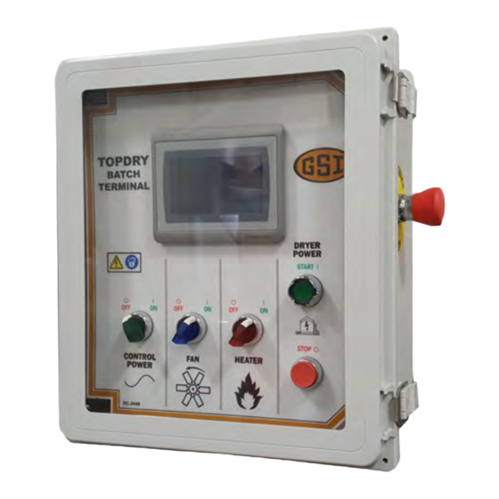
Page 30: The Topdry Batch Terminal Control Panel
Chapter 4: Control Panels The TopDry Batch Terminal Control Panel Along with the touchscreen user interface, the control panel contains all buttons and switches that allow you to set up and operate your dryer. Figure 4-1 The TopDry Batch Terminal NOTE: Images of the dryer, control panel, and user interface menus that are included in this guide are for illustrative purposes only and may not entirely resemble the actual product. - Page 31 Chapter 4: Control Panels Table 4-1 The components of the TopDry Batch Terminal (cont'd.) Item Name Description Fan switch Controls the main drying fans by way of the following modes: • OFF: The main drying fan(s) do not operate. • ON: The main drying fan(s) will operate continuously during the dry cycle.
-
Page 32: Powering On The Touchscreen
Chapter 4: Control Panels Powering on the Touchscreen What You Should Know The touchscreen on the TopDry Batch Terminal allows you to configure all timing functions, temperature controls, safety circuit checks and dryer setup parameters. It is designed to simplify operation by providing a touch control of the dryer and a self-diagnostic of the TopDry. - Page 33 Chapter 4: Control Panels Figure 4-3 The main menu with all displays shown NOTE: Due to the numerous configurations and options available, images of the dryer and it’s user interface that are included in this guide can differ from the actual product. Table 4-2 Description of the main menu’s buttons and displays Description Item...
-
Page 34: Configuring The Operational Settings For The Topdry Batch Terminal
Chapter 4: Control Panels Configuring the Operational Settings for the TopDry Batch Terminal By clicking the Setup icon on the main menu, you can configure settings for your system. These settings can vary depending on the equipment installed on your TopDry. What You Should Know Figure 4-4 The setup menu Item... - Page 35 Chapter 4: Control Panels To configure the TopDry Batch Terminal to your system: 1. Click the Setup icon from the main menu. 2. Set the following parameters: NOTE: The current settings are highlighted in green. Discharge Mode — Selects how the system determines when the cycle is complete. The available discharge modes are the following: •...
-
Page 36: The Timer Menu
Chapter 4: Control Panels The Timer Menu You can access and set all parameters for the timers from the same menu. The figure that follows illustrates and describes the parameter fields. Figure 4-5 Timer menu Item Name Item Name 1 — Purge time (seconds) 2 —... -
Page 37: Setting The Timers
Chapter 4: Control Panels Setting the Timers By clicking the Timers icon on the main menu, you can set the time for Batch Cool and Purge timers. What You Should Know The timers perform the following functions: • The Batch Cool Timer can be used to cool grain after the dry cycle. •... -
Page 38: The Temperature Menu
Chapter 4: Control Panels The Temperature Menu The temperature menu allows you to adjust the temperature limits for the daily operation of your dryer. Figure 4-6 The Temperature menu Item Name Item Name 1 — Grain max temp 4 — ON/OFF burner 2 —... -
Page 39: Setting The Temperature Setpoints For The Plenum And Grain From The Main Screen
Chapter 4: Control Panels Setting the Temperature Setpoints for the Plenum and Grain from the Main Screen By clicking anywhere within the plenum or grain temp rectangles, you can configure the temperature setpoints for the plenum and grain. These settings can also be set from the temperature screen. To adjust the Plenum or Grain setpoint temperature: 1. - Page 40 Chapter 4: Control Panels 2. Enter the desired temperature into the keypad and click enter or use up/down arrows to set desired temperature and click enter. Figure 4-8 Temperature adjustment Item Name Item Name Up/Down arrows Plenum temperature setpoint 1 — 2 —...
-
Page 41: The Information Menu
Chapter 4: Control Panels The Information Menu The information menu allows you to view alarms, setup a Watchdog message, view operation history and access a graphic diagnostic display of the control boards. Figure 4-9 The information menu Table 4-3 The information menu Description Item Name... -
Page 42: Factory Default Settings
Chapter 4: Control Panels Factory Default Settings You can reference the default factory settings to compare them with any changes you may have made. Table 4-4 TopDry Batch Terminal default settings Factory Value Parameter Units Drying Mode Time or Temp Mode Burner Hi-Lo or On/Off Mode Hi-Lo Dry and Cool Mode... -
Page 43: Chapter 5 Getting Started
Getting Started Topics Covered in this Chapter ▪ Pre-Season Inspections ▪ Testing the Dump Chutes ▪ Testing the Air Switch ▪ Testing the Burner Pre-Season Inspections Before the dryer is started or filled, fully inspect the TopDry system to ensure all components are in good working order. -
Page 44: Testing The Dump Chutes
Chapter 5: Getting Started Testing the Dump Chutes You must mark the Open and Closed positions and test that the winch is working properly. 1. Turn the winch handle until the chutes are in the closed position and inspect that the dump chutes are level. -
Page 45: Testing The Air Switch
Chapter 5: Getting Started Testing the Air Switch Airflow must be detected by the air switch before the heaters will begin to operate. Before You Begin • Make sure you have completed the pre-season inspections. • E-Stops are pulled out. •... -
Page 46: Testing The Burner
Chapter 5: Getting Started Testing the Burner The burners are connected to the heater ducts at the base of the bin. You must test the fans and burners prior to operating the TopDry system. Before You Begin • Make sure you have completed the pre-season inspections. •... -
Page 47: Chapter 6 Operation
Operation Topics Covered in this Chapter ▪ Shutting OFF the Dryer in an Emergency ▪ Initial Dryer Start-Up ▪ Shutting OFF the Dryer Shutting OFF the Dryer in an Emergency What You Should Know Never disable an Emergency Stop. Make sure all safety devices are installed and operate properly. -
Page 48: Initial Dryer Start-Up
Chapter 6: Operation Initial Dryer Start-Up Before You Begin • Make sure to complete all pre-season checks and tests. Refer to Chapter 5 Getting Started, page • Make sure there is wet grain ready to be loaded. Make sure all personnel are clear from the TopDry and loading systems before starting or operating your equipment. -
Page 49: Chapter 7 Troubleshooting
Troubleshooting Topics Covered in this Chapter ▪ TopDry Batch Terminal Error Messages TopDry Batch Terminal Error Messages Error Message Cause/Remedy The auxiliary contacts on the fan #1 motor starter failed to close when the Heater 1 Fan Contactor Aux starter was energized. Check that starter #1 is pulling in when energized. Contacts Failed to Close Check to see if the starter contacts are stuck closed or if the starter is Heater 1 Fan Contactor Aux... - Page 50 Chapter 7: Troubleshooting Error Message Cause/Remedy The LP gas vapor temperature sensor located in the gas pipe down- stream from the vaporizer coil on fan and heater #2 has opened indicating Heater 2 Gas Vapor Temp Hi-Limit that the vaporizer coil is running too hot. The vaporizer is adjusted by loosening the bolt and moving the vaporizer away from the flame.
-
Page 51: Chapter 8 Wiring Diagrams
Wiring Diagrams Figure 8-1 AutoFlow Fan/Heater - Modifications for Manual Batch PLC NOTE: Wiring changes are shown with dashed lines. 1. Fan starter overload to be wired in series with fan power wire to starter coil. 2. Surge suppressors must be added as shown. Failure to install suppressors will result in damage to components. - Page 52 Chapter 8: Wiring Diagrams Figure 8-2 E-Stop Circuit PLC Manual Batch PNEG-4902 TopDry Batch Control Terminal™...
- Page 53 Chapter 8: Wiring Diagrams Figure 8-3 Fan 1 Terminal Strips Located In the Top of the Batch PLC System Box PNEG-4902 TopDry Batch Control Terminal™...
- Page 54 Chapter 8: Wiring Diagrams Figure 8-4 Fan 2 Terminal Strips Located In the Top of the Batch PLC System Box PNEG-4902 TopDry Batch Control Terminal™...
- Page 55 Chapter 8: Wiring Diagrams Figure 8-5 Terminal Strips Located In Batch PLC System Box PNEG-4902 TopDry Batch Control Terminal™...
- Page 56 Chapter 8: Wiring Diagrams Figure 8-6 Tower Dryer Control Panel Wiring Diagram Figure 8-7 Tower Dryer Control Panel Wiring Diagram (Continued) PNEG-4902 TopDry Batch Control Terminal™...
- Page 57 Chapter 8: Wiring Diagrams Figure 8-8 Tower Dryer Control Panel Wiring Diagram (Continued) Figure 8-9 Tower Dryer Control Panel Wiring Diagram (Continued) PNEG-4902 TopDry Batch Control Terminal™...
- Page 58 Chapter 8: Wiring Diagrams Figure 8-10 Tower Dryer Control Panel Wiring Diagram (Continued) PNEG-4902 TopDry Batch Control Terminal™...
- Page 59 Chapter 8: Wiring Diagrams Figure 8-11 Manual Batch PLC TopDry PNEG-4902 TopDry Batch Control Terminal™...
- Page 60 Chapter 8: Wiring Diagrams Figure 8-12 Manual Batch PLC TopDry (Continued) PNEG-4902 TopDry Batch Control Terminal™...
- Page 61 Chapter 8: Wiring Diagrams Figure 8-13 Manual Batch PLC TopDry (Continued) PNEG-4902 TopDry Batch Control Terminal™...
- Page 62 NOTES PNEG-4902 TopDry Batch Control Terminal™...
-
Page 63: Gsi Group, Llc Limited Warranty
12 months after sale to the original end-user or if a foreign sale, 14 months from arrival at port of discharge, whichever is earlier. The end-user’s sole remedy (and GSI’s only obligation) is to repair or replace, at GSI’s option and expense, products that in GSI’s judgment, contain a material defect in materials or... - Page 64 Authorities having jurisdiction should be consulted before installations are made. 1004 E. Illinois St. Assumption, IL 62510-0020 Phone: 1-217-226-4421 Fax: 1-217-226-4420 www.gsiag.com GSI is a worldwide brand of AGCO Corporation. Copyright © 2018 by The GSI Group, LLC Printed in the USA CN #334097...
Need help?
Do you have a question about the TopDry Terminal 24 and is the answer not in the manual?
Questions and answers