Table of Contents
Advertisement
Quick Links
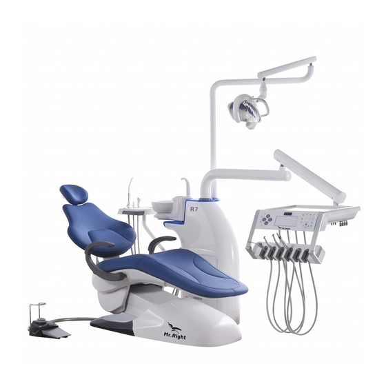
User Manual R7
1. Gerneral information .......................................................2
2. Safety information ...........................................................3
3. Construction brief instruction...........................................4
4. Specification.....................................................................6
5. Installation and Settings....................................................7
6. Operation direction...........................................................9
7. Maintenance notice.........................................................18
8. Clearing of faults..............................................................20
9. Waste disposal.................................................................21
10. Taboos and precautions..................................................22
11. Electrical schematic diagram of dental unit.....................24
12. Water and air connection diagram...................................25
1
Contents
1
Operation instruction
Advertisement
Table of Contents

Summary of Contents for Mr.Right R7
- Page 1 User Manual R7 Operation instruction Contents 1. Gerneral information ............2 2. Safety information ............3 3. Construction brief instruction...........4 4. Specification..............6 5. Installation and Settings............7 6. Operation direction............9 7. Maintenance notice............18 8. Clearing of faults..............20 9. Waste disposal..............21 10. Taboos and precautions..........22 11.
-
Page 2: General Notice
User Manual R7 Operation instruction 1.General notice 1.1 Esteemed users IT is our pleasure that you bought this dental unit made , this user manual carefully in order to master this machine as soon as possible 1.2 Usage notice Read this user manual carefully in order to familiarize... -
Page 3: Safety Notice
User Manual R7 Operation instruction 2.2.Safety notice 2.1 Dangerous class of symbols Comply with the warming and safety notice, to avoid casualty or property loss.please be attentioned to the marks below: Warning A possibly dangerous situation that could result in serious bodily injury or death. - Page 4 User Manual R7 Operation instruction 2.5 Ventilation Slots Under no circumstances may the ventilation slots on the unit To over heat. Do not spray liquid such as disinfectants in into the ventilation slots. This may lead to malfunctions. 3.Construction 3.1 Construction diagram...
- Page 5 User Manual R7 Operation instruction 3.2 Description of construction This dental unit consists of patient chair, connector of handpiece,dental lamp,3-way Syring,weak saliva ejector,stronge saliva ejector,spiton,viewer,foot controler, air and water supply system. Electricity,Water and air are supplied from the chair base. There are air filter, Pressure reducing valve, water filter and electricity filter for purifying the water,air and electricity supplying to this device.
- Page 6 User Manual R7 Operation instruction 4.Specication Power supply: 230V AC±22V , 50HZ±1HZ; Power consumption: ≤600W; Rated current: 3.2A; Fuse: 05×20, 6.3A; Outside fuse for power supply:230V AC 16A (delaying sytle) Safety class:Class Ⅱ Protection level of anti electric shock:A style applied parts...
-
Page 7: Installation And Setting
User Manual R7 Operation instruction 5.Installation and setting 5.1 Installation conditions To make sure dental unit work well the conditions of air, water, electricity for the device should be Air supply air pressure: 0.5 MPa--0.8MPa Folw volume >50L/min Water supply Water pressure: 0.2MPa--0.4MPa Current volume>10Lmin Power supply AC 220V±10% 50Hz±1Hz... -
Page 8: Steps Of Installation
User Manual R7 Operation instruction 5.2.2 Steps of installation A)Patient chair installation Fit the chair base at the planned place. If the installation floor is not flat enough,user can fix the five pcs of enclosed leveling screws(M12*15) into the five screwholes (M12),adjust the height of five screws to make sure the dental unit stand firmly onto the ground.and then fix four pieces of... - Page 9 User Manual R7 Operation instruction 6.Operation instruction 6.1 Master switch of water,electricity,and air This switch is set at the back of base,Pulling out means power,water and air on,Pushing down means power,water and air off. Notice For the sake of protection,prolong lifespan of the device, as well as saving power,please get this mater switch off.
- Page 10 A is ready to suppl water. Turn to B side,means the bottle B is ready to supply water(Front for A bottle,behind for B bottle) 7.3Function of cleaning and disinfection(only for R7 and R7 floor mounted) This is the function of cleaning and disinfecting handpiece water tube. Operation steps descriped as below: A) preparation jobs Add pure water into bottle A,and add bottle B the disinfectant liquid.(advice of 500mg/L...
- Page 11 User Manual R7 Operation instruction C) Turn the disnfection switch to OFF side, Put handpiece connective end back to the rack after finishing flushing the tube. Notice There is a air pressure reducing valve in the man machine box for controlling its level during 0.2-0.25MPa,but it is set before delivery to user,please do not adjust the valve except the...
- Page 12 User Manual R7 Operation instruction Symbol Meanings Symbol Meanings Seat rising up Setting button Seat getting down X-ray film viewer button Backrest rising up Dental Lamp Backrest getting down Heating Shock position Tumbler filling Entry/exit position Flushing spittoon Comprehensive key for Flushing,lighting...
- Page 13 8.14 Heating: this button is for control of heating water,it owns the protection system of over heating.and the the temperature is set before delivery to user. Notice Heating button of R7: the heating button of the assistant control panel control the heater in the main machine...
- Page 14 “+” or “-” key to set the time. Normally for Anesthesia,whitening,curing,dentist need to set the time on phone and waiting,now R7 dental unit could set on panel to remind our dentist,like the alarm clock .please press the setting key again means confirm setting.The flash will stop. Press the “setting”key again,will start to countdown.
- Page 15 User Manual R7 Operation instruction Notice A)Recovery pose of patient chair do not need to be set, it runs up to its limited B)Heating button work as funciton of start or finish, its signal light will b flashing when it heating,and it will keep lighting when finish heating.
- Page 16 User Manual R7 Operation instruction Controlling methods:turning clockwise is for reducing air 8.22 Handpiece cooling water control Handpiece cooling water control knob is located at the right side of instrument tray, their symbols are: Handpiece cooling water control methods: turning clockwise is for reducing water 8.23 Handpiece spray control...
- Page 17 8.28 E lectrocardiogram equipment and Intraoral camera(only suit for R7 implant) Electrocardiogram equipment:The doctor can observe the patient's heart electrical activity Intraoral camera:The doctor can real-time video inspections need to check the parts.
- Page 18 User Manual R7 Operation instruction 8.29 Multi-function stainless steel plate 3 stainless steel plate,different size,can remove,clean and disinfection. 7.Maitenance and preservation For daily maintenance, Please keep this device clean, keep passage of tube system clear,examin that there is no leaking of water or air.the rotatable parts should be applied to lubricant oil on schedule to keep it at well performance 7.1 water filter...
-
Page 19: Air Filter Regulator
User Manual R7 Operation instruction Can not overexert while installing the water filter,avoid crushing the filter. keep the crystal cup in well sealed. 7.2 Air filter regulator This dental unit is equipped with a air filter regulator at the air-in end of air suppply tube in the front base box,in order to ensure the air supply clean,stable and dry,as well as reducing the air pressure meanwhile.it can also filter impurity and water in the air.so there must be some wasted... - Page 20 User Manual R7 Operation instruction 8. Malfunction removal Malfunction Description Malfunction Causes Removal methods 1.Bad bur Contact the handpiece seller 1.Powerless handpiece 2.Bearing fault 3.Low driving pressure Check the air pressure 1.Air or water pressure not high Raise the air or water pressure 2.Powerless saliva ejector...
- Page 21 User Manual R7 Operation instruction 12.Leaking air when handpiece Rack valve gets loose Adjust the rack valve stops working 9.Waste treatment No handling these dental unit waste by ways of household waste done They must be entirely disinfected,sterilized and purified before being dismantled or being thrown away...
- Page 22 User Manual R7 Operation instruction 5.The resistance in the electric motor contain lead 6.PCB bonding pad contain lead 10.Taboos, warnings and notices 1.Read and master the user manual completely before working on this device 2.Operate according to the warnings and instructions of this device.
- Page 23 User Manual R7 Operation instruction exchanged. 24.Diameter of bars should be between 1.59 to 1.60mm (regulation by ISO1797 Class 3),Max length is 25mm (regulation by ISO6360-1) 25. Only after being equipped with bars and dental restoration tools, high speed handpieces can be used 26.
-
Page 24: Electrical Schematic Diagram
User Manual R7 Operation instruction 11.Electrical schematic diagram... - Page 25 User Manual R7 Operation instruction Water-air layout diagram...
- Page 26 User Manual R7 Operation instruction R7 air layout diagram 1.Crystal tubes are for air layout system 2.Blue PU tube are for air layout system 3.PVC tubes (25MM of diagram) are for waste outlet...
Need help?
Do you have a question about the R7 and is the answer not in the manual?
Questions and answers