
Summary of Contents for Fokke RC MESSERSCHMITT BF-109 E4
-
Page 1: Technical Data
INSTRUCTION For advanced modelers MESSERSCHMITT BF-109 E4 Technical Data: Wingspan: 1980mm Length: 1752mm Weight: 9kg Engine: 30-50cc gas engine Electric motor-2500-3000W... - Page 2 Dear Friend, Congratulations on your choice. The 1/5 scale Full Kit of the famous German Messerschmitt BF 109 E is offered in a composite format with most of the detail work already done. However we appreciate that you derive great pleasure from building your models and so we have left some building for you to do.
- Page 3 LASER CUT WING PARTS 3mm poplar plywood, 3mm balsa, 4mm balsa, pine stringers F1 – F2 3mm plywood ribs 8 pcs L1 – L2 3mm plywood longerone det. 8 pcs 3mm balsa 100x1000mm sheet 3 pcs 4mm balsa 100x1000mm sheet 8 pcs 5x5x850mm pine stringer 2 pcs...
- Page 4 Profiles of all fuselage laser cut parts...
- Page 5 Profiles of all wing laser cut parts FUSELAGE ASSEMBLY Start by epoxying the relevant pieces into the fuselage. Note: Follow the photos to get the correct installation sequence. Step 1 Step 2 Install the Root Rib T10 into the wing root area. Do the same with T9 to the other side wing root.
- Page 6 Step 3 Laminate Fuselage Formers T7a & T7b together to form a 1/4 thick former. Epoxy into the Wing Root Ribs previously installed and to the Composite Fuselage all the way round. Step 5 Step 4 Follow step 4 and glue in the other side Retract Plate to the Laminate Gear Plates T8a &...
- Page 7 Step 6 Step 7 Glue in Former T6a. Epoxy into Fuselage and to the Gear Plates Install the engine box. Simple twist and turn interlocking as shown. construction. Just follow the photos. Note the orientation of the box sides.
- Page 8 Step 8 Part T2 goes at the top. Step 9 ….and next T5...
- Page 9 Step 10 Part T3 is on the bottom of the box. Step 11 Glue T1a, T1b and T1c together. Step 12 Close the box with these laminated parts.
- Page 10 Step 13 Next is the detail T6b. When you finished the engine box we recommend covering with glass 163gr and Epoxy Resin. Step 14 The final step – glue the servo tray T11 in place.
-
Page 11: Wings Assembly
WINGS ASSEMBLY We recommend the use of Epoxy Resin adhesive for the wing construction. All ribs are at 90 degrees to the work surface. Follow the drawing for spacing and angles! Sequence is shown below: Step 1 Laminate Root Ribs F1 & F1a together. Lay down a 5x10x850mm pine lower spar and start assembling the ribs and the spar shear webs from the Root Rib end. - Page 12 Step 3 Continue steps 1 & 2 to complete the wing structure. Follow the photos sequence. Parts F3 to F11 are from 4mm balsa wood. Parts L-3 to L-10 are from 3mm balsa wood. Step 2 Ensure that the wing tubes are at 90° to the Root Rib.
- Page 14 Step 4 Step 5 Install the upper and lower 5x10x600mm pine spars. Install 5x10x850mm pine strip to the trailing edge of the wing.
- Page 15 Step 6 Install 5x5x850mm pine strip to the leading edge of the wing. Step 7 For better contact of the two wing tip skins glue balsa strip 5 x 3mm on each wing skin. Apply Epoxy Resin adhesive to all contact surfaces with wing top skin.
- Page 16 Step 10 Ensure that all of the wing structures to be glued to the composite skins have adequate glue on them. Carefully position the wing structure into the top wing skin first then position the lower one. Tape closed any openings around the edges and weight down the wing so as to achieve good gap-free joints inside and around the edges.
- Page 18 Before installing any of the composite details the surface should be roughened up with 80 grit abrasive paper. Quick set Epoxy or Cyanoacrylate glue. ASSEMBLING AILERONS, FLAPS AND RUDDER We recommend Robart hinges. Aileron hinge installation: Mark the position of the hinges making sure they line up with the blocks glued into the wing previously. Cut a 20mm wide gap into the ailerons leading edge.
- Page 20 To cover the wood parts can use the product white fabric ORASTICK of www.oracover.de...
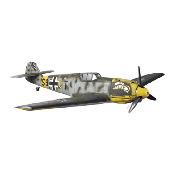
- Page 22 FINISHED...
- Page 23 Good luck with the assembly and have fun with the flights! www.fokkerc.com fokkerc@abv.bg...
Need help?
Do you have a question about the MESSERSCHMITT BF-109 E4 and is the answer not in the manual?
Questions and answers